Page 1 of 93

8Electrical equipment
V3 MR-372-J84-86A050$TOC.mif
V3
86A
"The repair procedures given by the manufacturer in this document are based on the
technical specifications current when it was prepared.
The procedures may be modified as a result of changes introduced by the
manufacturer in the production of the various component units and accessories from
which his vehicles are constructed."
V3
All rights reserved by Renault s.a.s.
Edition Anglaise
Copying or translating, in part or in full, of this document or use of the service part
reference numbering system is forbidden without the prior written authority of
Renault s.a.s.
© Renault s.a.s. 2008
RADIO
LPN RADIO
Vdiag No: C4
Fault finding - Introduction 86A - 2
Fault finding - List and location of components 86A - 8
Fault finding - Role of components 86A - 9
Fault finding - Operating diagram 86A - 10
Fault finding - Function 86A - 11
Fault finding - Configurations and programming 86A - 12
Fault finding - Replacement of components 86A - 13
Fault finding - Fault summary table 86A - 14
Fault finding - Interpretation of faults 86A - 15
Fault finding - Conformity check 86A - 47
Fault finding - Status summary table 86A - 52
Fault finding - Parameter summary table 86A - 53
Fault finding - Interpretation of parameters 86A - 54
Fault finding - Command summary table 86A - 59
Fault finding - Customer complaints 86A - 60
Fault finding - Fault Finding Chart 86A - 62
Page 2 of 93

86A-2
MR-372-J84-86A050$059.mif
V3
86A
RADIO
Fault finding - Introduction
1. SCOPE OF THIS DOCUMENT
This document presents the fault finding procedure applicable to all computers with the following specifications:
2. PREREQUISITES FOR FAULT FINDING
Documentation type
Fault finding procedure (this manual):
–Assisted fault finding (integrated into the diagnostic tool), Dialogys.
Wiring Diagrams:
–Visu-Schéma (CD-ROM), paper.
Type of diagnostic tools
–CLIP + multiplex line sensor
Special tooling required
3. REMINDERS
Procedure
Scénic II ph2:
To run fault finding on the vehicle computers, switch on the forced + after ignition feed.
Proceed as follows:
*LPN: Low Price NavigationVehicle(s): Espace IV phase 2, Scénic II phase 2,
Trafic II phase 2, Kangoo 2
Function concerned: Radio, satellite navigationName of computer: LPN* radio navigation
VDIAG NO: C4
Special tooling required
Multimeter
Elé. 1681 Universal bornier
Switch on the forced + after ignition feed:
–with the vehicle card in the card reader,
–press and hold the Start button (longer than 5 seconds) with start-up conditions not fulfilled,
–connect the diagnostic tool and perform the required operations.
Switching off the forced + after ignition feed:
Press the Start button twice briefly (less than 3 seconds).
See that the + after ignition feed has been cut off by checking that the computer warning lights on the instrument
panel have gone out.
LPN_VC4_PRELI
MR-372-J84-86A050$059.mif
LPN RADIO
Vdiag No: C4
Page 3 of 93

Espace IV ph2:
In order to save energy, the Espace IV Phase 2 UCH cuts off the +")
86A-3
MR-372-J84-86A050$059.mif
V3
LPN RADIO
Vdiag No: C4RADIO
Fault finding - Introduction86A
Procedure (continued)
Espace IV ph2:
In order to save energy, the Espace IV Phase 2 UCH cuts off the + after ignition feed after 3 minutes.
To run fault finding on a computer, it is possible to force the + after ignition feed on for 1 hour by applying the
following procedure:
–Press the card unlocking button.
–Insert the card into the card reader.
–Press the Start button (interrupting the timed + after ignition feed mode).
–Press and hold the start button for over 5 seconds until the engine immobiliser warning light starts to
flash rapidly (4 Hz).
This "forced + after ignition feed" mode remains active for 1 hour.
Pressing the start button or removing the card from the reader cuts off the forced + after ignition feed but does not cut
off the timed forced + after ignition feed mode. As long as one hour has not passed, the + after ignition feed function
restarts the forced + after ignition feed for the remaining time.
Trafic II ph2 and Kangoo 2:
To run fault finding on the vehicle computers, switch on the forced + after ignition feed.
Faults
Faults are displayed as present or stored (they appeared in a certain context and have since disappeared, or they
are still present but cannot be diagnosed in the current context).
The present or stored status of faults should be taken into consideration when the diagnostic tool is used following
the + after ignition supply being switched on (without operating the system components).
For a present fault, apply the method described in the section on Interpretation of faults.
For a stored fault, note the faults displayed and apply the notes section.
If the fault is confirmed when the instructions in the Notes section are applied, the fault is present. Deal with the fault
If the fault is not confirmed, check:
–the electrical lines which correspond to the fault,
–the connectors on these lines (corrosion, bent pins, etc.),
–the resistance of the component detected as defective,
–the condition of the wires (melted or split insulation, wear).
Page 4 of 93

86A-4
MR-372-J84-86A050$059.mif
V3
LPN RADIO
Vdiag No: C4RADIO
Fault finding - Introduction86A
Conformity check
The aim of the conformity check is to check data that does not produce a fault on the diagnostic tool because the
data is inconsistent. Therefore, this stage is used to:
–carry out fault finding on faults that do not have a fault display, and which may correspond to a customer
complaint.
–check that the system is operating correctly and that there is no risk of a fault recurring after repair.
This section gives the fault finding procedures for statuses and parameters and the conditions for checking them.
If a status is not behaving normally or a parameter is outside the permitted tolerance values, consult the
corresponding fault finding page.
Customer complaints - Fault finding chart
If the test with the diagnostic tool is OK but the customer complaint is still present, the fault should be processed by
customer complaints.
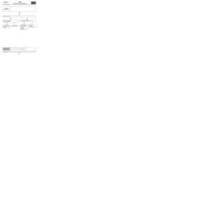
A summary of the overall procedure to follow is provided on the following page in the form
of a flow chart.
Page 5 of 93
86A-5
MR-372-J84-86A050$059.mif
V3
LPN RADIO
Vdiag No: C4RADIO
Fault finding - Introduction86A
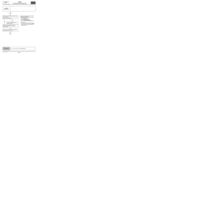
See ALP no. 1
Conformity check
no
The cause is
still presentFault
solved
Use fault finding charts (ALPs)
no
The cause is
still presentFault
solved
Contact the Techline with the
completed fault finding log
4. FAULT FINDING PROCEDURE
Perform a pre-diagnostic
on the system
Print the system fault finding log
(available on CLIP and in the
Workshop Repair Manual or
Technical Note)
Connect CLIP
no
Dialogue with
computer?
yes
Read the faults
no
Faults
present
yes
Deal with present faults
Deal with stored faults
no
The cause is
still presentFault
solved
yes
Page 6 of 93

Wiring check
Fault finding problems
Disconnecting the connectors")
86A-6
MR-372-J84-86A050$059.mif
V3
LPN RADIO
Vdiag No: C4RADIO
Fault finding - Introduction86A
4. FAULT FINDING PROCEDURE (CONTINUED)
Wiring check
Fault finding problems
Disconnecting the connectors and/or manipulating the wiring harness may temporarily remove the cause of a fault.
Electrical measurements of voltage, resistance and insulation are generally correct, especially if the fault is not
present when the analysis is made (stored fault).
Visual inspection
Look for damage under the bonnet and in the passenger compartment.
Carefully check the fuses, insulators and wiring harness routing.
Look for signs of oxidation.
Tactile inspection
While manipulating the wiring harness, use the diagnostic tool to note any change in fault status from stored to
present.
Make sure that the connectors are properly locked.
Apply light pressure to the connectors.
Twist the wiring harness.
If there is a change in status, try to locate the source of the fault.
Inspection of each component
Disconnect the connectors and check the appearance of the clips and tabs, as well as the crimping (no crimping on
the insulating section).
Make sure that the clips and tabs are properly locked in the sockets.
Check that no clips or tabs have been dislodged during connection.
Check the clip contact pressure using an appropriate model of tab.
Resistance check
Check the continuity of entire lines, then section by section.
Look for a short circuit to earth, to + 12 V or to another wire.
If a fault is detected, repair or replace the wiring harness.
Page 7 of 93

86A-7
MR-372-J84-86A050$059.mif
V3
LPN RADIO
Vdiag No: C4RADIO
Fault finding - Introduction86A
5. FAULT FINDING LOG
You will always be asked for this log:
●when requesting technical assistance from Techline,
●for approval requests when replacing parts for which approval is mandatory,
●to be attached to monitored parts for which reimbursement is requested. The log is needed for warranty
reimbursement, and enables better analysis of the parts removed.
6. SAFETY INSTRUCTIONS
Safety rules must be observed during any work on a component to prevent any damage or injury:
–check the battery voltage to avoid incorrect operation of computer functions,
–Use the proper tools. IMPORTANTIMPORTANT
Any fault on a complex system requires thorough fault finding with the appropriate tools. The
FAULT FINDING LOG, which should be completed during the procedure, enables you to keep
track of the procedure which is carried out. It is an essential document when consulting the
manufacturer.
IT IS THEREFORE ESSENTIAL THAT THE FAULT FINDING LOG IS FILLED OUT EVERY TIME IT IS
REQUESTED BY TECHLINE OR THE WARRANTY RETURNS DEPARTMENT
Page 8 of 93
86A-8
MR-372-J84-86A050$118.mif
V3
86A
RADIO
Fault finding - List and location of components
Refer to the multimedia function section (see 86C, multimedia).
MR-372-J84-86A050$118.mif
LPN RADIO
Vdiag No: C4


.
MR-372-J84-86A050$118.mif
LPN RADIO
Vdiag N")