Page 9 of 128
AUTOMATIC TRANSMISSION
Fault finding – System operation23A
23A-9V4 MR-372-J84-23A050$132.mif
SIEMENS TA2000
Vdiag No.: 10-11-15
MODULAR CONNECTOR
AMultifunction switch
BHydraulic electronic interface
COil pressure sensor
DTurbine speed sensor
EExchanger flow lock-up solenoid valveFemale connection
(connector leading to switch, interface) sensors,
exchanger flow lock-up solenoid valve)Male connection
(connector coming from computer)
Page 10 of 128
AUTOMATIC TRANSMISSION
Fault finding – System operation23A
23A-10V4 MR-372-J84-23A050$132.mif
SIEMENS TA2000
Vdiag No.: 10-11-15
COMPUTER INPUTS AND OUTPUTS
INPUTS OUTPUTS
Diagnostic socket
Automatic
transmission
computer
Solenoid valve control
+ battery feed
+ after ignition feed + warning lights display
Intersystem signals + diagnostic
socketIntersystem signal + diagnostic
socket
Driver actions (brake light switch,
gear selector, multifunction
switch)Gear lever lock
AUTO sensors (turbine speed, oil
pressure, oil temperature)Reversing lights
Earth
Wire connection
Multiplexed connections
Page 11 of 128

AUTOMATIC TRANSMISSION
Fault finding – Replacement of components23A
23A - 11V4 MR-372-J84-23A050$198.mif
SIEMENS TA2000
Vdiag No.: 10-11-15AUTOMATIC TRANSMISSION
Fault finding – Replacement of components
REPLACING THE COMPUTER
If Techline approves the computer replacement, proceed as follows:
–Note the gearbox oil condition meter code in the Identification menu: ID018 Oil condition meter and the
date of the last gearbox oil service ID017: Gearbox oil service date.
–Switch off the ignition.
–Replace the computer.
–If necessary, change the computer configuration in the Enter configuration menu.
–Enter the VIN into the computer with diagnostic tool command VP001 Enter VIN.
–Enter the oil condition meter code from the old automatic transmission computer (found in the Identification
menu) using command VP015 Transfer oil condition meter.
–Enter the gearbox oil service date with command VP016 Enter gearbox oil service date.
–Enter the After-Sales service date with diagnostic tool command VP009 Enter last After-Sales service
date,
–Carry out a check with the diagnostic tool, on the Identification screen.
–Switch off the ignition.
REPLACING AN AUTOMATIC TRANSMISSION COMPONENT
For the replacement of the other components which make up the automatic transmission, (see MR 364 Mechanical,
23A, Automatic transmission (For MEGANE II) and see MR 370 Mechanical, 23A, Automatic transmission
(For SCENIC II)).
After the replacement of one or more gearbox components, or after reprogramming, auto-program the solenoid
valves using command RZ005: Self-adapting programs (see Dealing with command modes). IT IS ESSENTIAL TO CONTACT YOUR TECHLINE BEFORE REPLACING AN AUTOMATIC TRANSMISSION
COMPUTER.
MR-372-J84-23A050$198.mif
Page 12 of 128

AUTOMATIC TRANSMISSION
Fault finding – Replacement of components23A
23A - 12V4 MR-372-J84-23A050$198.mif
SIEMENS TA2000
Vdiag No.: 10-11-15
PROGRAMMING
●VP001 Enter VIN:
As it is necessary to enter the VIN each time dialogue is established with the diagnostic tool, it must be
programmed into each vehicle computer whenever a computer is replaced.
Programming procedure:
–Connect the diagnostic tool.
–Consult the fault finding procedure for the automatic transmission.
–Select configuration VP001 Enter VIN.
–Enter the VIN.
–Exit fault finding mode.
–Switch off the ignition.
–Wait for the end of Power-latch: over 10 seconds.
●VP009 Enter last After-Sales operation date:
Every time work is carried out on the automatic transmission in the workshop, enter the date of the
operation.
Select command VP009 Enter last After-Sales operation date on the diagnostic tool, then use the tool's
keypad to enter the date of the operation.
●VP015 Transfer oil condition meter:
Transfer the oil wear counter code from the old computer.
Select command VP015 Transfer oil wear counter on the diagnostic tool, then use the keypad to enter
the code found on the replaced computer.
●VP016 Enter gearbox oil service date:
Select command VP016 Enter gearbox oil service date on the diagnostic tool, then use the keypad to
enter the date found on the replaced computer.
* The immobiliser warning light will flash a few seconds after the ignition is switched off.
Page 13 of 128

AUTOMATIC TRANSMISSION
Fault finding – Replacement of components23A
23A - 13V4 MR-372-J84-23A050$198.mif
SIEMENS TA2000
Vdiag No.: 10-11-15
For SCENIC II only
Reading automatic transmission configuration
The read-configuration commands (LCXXX) are used to display the current computer configuration in relation to the
equipment installed in the vehicle.
Writing automatic transmission configuration
The write-configuration commands (CFXXX) are used to configure the computer for the equipment installed in the
vehicle.
These three settings are important because they optimise transmission operation for the vehicle. If they are not
entered properly, automatic transmission operation may be impaired.Configuration reading Configuration
LC014 Engine torque control function WITH/WITHOUT
LC015 Electronic stability control WITH/WITHOUT
LC017 Shift lock connection fault finding WITH/WITHOUT
Configuration reading Configuration
CF322 Engine torque control function WITH/WITHOUT
CF314 Electronic stability program (ESP) WITH/WITHOUT
CF325 Shift lock connection fault finding WITH/WITHOUT
Page 14 of 128

AUTOMATIC TRANSMISSION
Fault finding – Replacement of components23A
23A - 14V4 MR-372-J84-23A050$198.mif
SIEMENS TA2000
Vdiag No.: 10-11-15
For SCENIC II only
CONFIGURATIONS OF THE AUTOMATIC TRANSMISSION COMPUTER CF322: ENGINE TORQUE CONTROL
FUNCTION
–This function reduces engine torque when shifting gears.
–To apply this configuration, the vehicle must have the ignition on, engine stopped and gear lever in position P
or N.
–This function tells the computer what torque to apply to the engine when changing gears.
–Select configuration CF322 "Engine torque control function".
–Configure the computer WITH or WITHOUT.
–Exit fault finding mode.
–Switch off the ignition.
–Wait 15 seconds for the power-latch to end.
–re-read the configuration for confirmation.
CF314 "ELECTRONIC STABILITY PROGRAM (ESP)"
–This function limits over- or under-steering by braking certain wheels and controlling engine torque.
–To apply this configuration, the vehicle must have the ignition on, engine stopped and gear lever in position P
or N.
–This function lets the automatic transmission computer downshift for ESP adjustments.
–Select configuration CF314 "Electronic stability program (ESP)".
–Configure the computer WITH or WITHOUT.
–Exit fault finding mode.
–Switch off the ignition.
–Wait 15 seconds for the power-latch to end.
–re-read the configuration for confirmation.
CF325 "SHIFT LOCK CONNECTION FAULT FINDING"
–To apply this configuration, the vehicle must have the ignition on, engine stopped and gear lever in position P
or N.
–Select configuration CF325 "Shift lock connection fault finding".
–Configure the computer WITH or WITHOUT.
–Exit fault finding mode.
–Switch off the ignition.
–Wait 15 seconds for the power-latch to end.
–re-read the configuration for confirmation.
Page 15 of 128

AUTOMATIC TRANSMISSION
Fault finding – Fault summary table23A
23A - 15V4 MR-372-J84-23A050$264.mif
SIEMENS TA2000
Vdiag No.: 10-11-15AUTOMATIC TRANSMISSION
Fault finding – Fault summary table
* EVS: Sequence solenoid valvesTool fault Diagnostic tool title
DF002 Computer
DF003 Analogue sensor feed
DF005 Oil pressure sensor circuit
DF009 Multifunction switch prohibited position
DF012 Solenoid valve feed
DF016 Lockup solenoid valve circuit
DF017 Exchanger flow rate solenoid valve circuit
DF018 Lockup slip
DF023 Gearbox oil temperature sensor circuit
DF029 Multifunction switch in unstable position
DF036 Pressure regulating solenoid valve circuit
DF038 Turbine speed sensor circuit
DF048 Vehicle speed signal
DF049 Pressure regulation
DF055 Injection →→ → →
automatic transmission connection
DF064 Display circuit
DF085 EVS*1 sequence solenoid valve circuit
DF086 EVS*2 sequence solenoid valve circuit
DF087 EVS*3 sequence solenoid valve circuit
DF088 EVS*5 sequence solenoid valve circuit
DF089 EVS*4 sequence solenoid valve circuit
DF093 Sequential gear lever circuit
DF095 Shift lock electromagnet circuit
DF109 Engine torque multiplex signal
DF112 *EVS6* sequence solenoid valve circuit
DF114 Pedal position multiplex signal
MR-372-J84-23A050$264.mif
Page 16 of 128
AUTOMATIC TRANSMISSION
Fault finding – Fault summary table23A
23A - 16V4 MR-372-J84-23A050$264.mif
SIEMENS TA2000
Vdiag No.: 10-11-15
* RR: rear
* FR: frontTool fault Diagnostic tool title
DF116 Engine multiplex speed signal
DF117 Left RR* wheel multiplex speed signal
DF118 Right RR* wheel multiplex speed signal
DF119 Brake pedal position
DF122 Passenger compartment computer connection
DF123 ABS computer connection
DF126 Turbine speed signal
DF131 Slip
DF144 Coolant temperature multiplex signal
DF174 ABS fault detection
DF175 Left-hand FR* wheel multiplex speed signal
DF176 Right-hand FR* wheel multiplex speed signal
DF177 Automatic transmission overheating
 1
1 2
2 3
3 4
4 5
5 6
6 7
7 8
8 9
9 10
10 11
11 12
12 13
13 14
14 15
15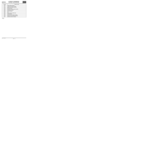 16
16 17
17 18
18 19
19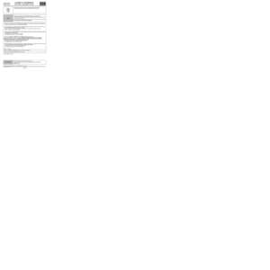 20
20 21
21 22
22 23
23 24
24 25
25 26
26 27
27 28
28 29
29 30
30 31
31 32
32 33
33 34
34 35
35 36
36 37
37 38
38 39
39 40
40 41
41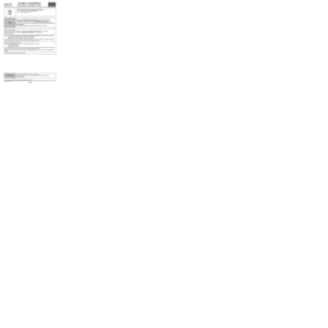 42
42 43
43 44
44 45
45 46
46 47
47 48
48 49
49 50
50 51
51 52
52 53
53 54
54 55
55 56
56 57
57 58
58 59
59 60
60 61
61 62
62 63
63 64
64 65
65 66
66 67
67 68
68 69
69 70
70 71
71 72
72 73
73 74
74 75
75 76
76 77
77 78
78 79
79 80
80 81
81 82
82 83
83 84
84 85
85 86
86 87
87 88
88 89
89 90
90 91
91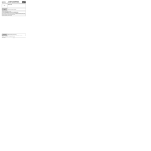 92
92 93
93 94
94 95
95 96
96 97
97 98
98 99
99 100
100 101
101 102
102 103
103 104
104 105
105 106
106 107
107 108
108 109
109 110
110 111
111 112
112 113
113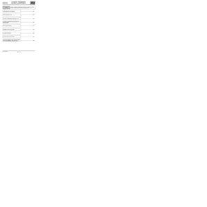 114
114 115
115 116
116 117
117 118
118 119
119 120
120 121
121 122
122 123
123 124
124 125
125 126
126 127
127

