Page 97 of 128

AUTOMATIC TRANSMISSION
Fault finding – Parameter summary table23A
23A - 97V4 MR-372-J84-23A050$660.mif
SIEMENS TA2000
Vdiag No.: 10-11-15AUTOMATIC TRANSMISSION
Fault finding – Parameter summary table
ET142
BRAKE PEDAL DEPRESSED
NOTESThere must be no present or stored faults.
This status indicates the position of the brake pedal
The status is YES when the brake pedal is pressed.
The status is NO when the brake pedal is not pressed.
If the status does not function as specified above, use the interpretation of fault DF119 Brake pedal position.
Disconnect the computer.
Check the cleanliness and condition of the connections.
Check the continuity, insulation and the absence of interference resistance on the following connections:
●Connection code 5A between components 119 and 160.
If the connection is faulty and there is a repair procedure (see Technical Note 6015A, Electrical wiring repair,
Wiring: Precautions for repair), repair the wiring, otherwise replace it.
If the fault is still present, replace the brake sensor.
If the fault is still present, contact the Techline.
DP0TA2000_V10_ET142/DP0TA2000_V11_ET142/DP0TA2000_V15_ET142
MR-372-J84-23A050$660.mif
Page 98 of 128
AUTOMATIC TRANSMISSION
Fault finding – Parameter summary table23A
23A - 98V4 MR-372-J84-23A050$660.mif
SIEMENS TA2000
Vdiag No.: 10-11-15
ET155
FIXED THIRD CONTACT
NOTESThe vehicle does not have a fixed 3rd (D3).
Ignore ET155 "Fixed third contact".
DP0TA2000_V10_ET155/DP0TA2000_V11_ET155/DP0TA2000_V15_ET155
Page 99 of 128

AUTOMATIC TRANSMISSION
Fault finding – Parameter summary table23A
23A - 99V4 MR-372-J84-23A050$660.mif
SIEMENS TA2000
Vdiag No.: 10-11-15
ET157
GEAR LEVER UNLOCKING
NOTESThere must be no present or stored faults.
This status indicates whether or not the gear lever is unlocked.
Lever in position P.
The status is YES when the brake pedal is pressed.
The status is NO when the brake pedal is not pressed.
Lever in any position except P.
The status is YES whether or not the brake pedal is pressed.
Check that the instrument panel indicates that the lever is in position P.
Check that, when the brake pedal is pressed, the "Press brake pedal" message disappears from the instrument
panel.
Check the gear lever operation up to the multifunction switch.
Adjust the cable if necessary.
Check that statuses ET154, ET123, ET124 and ET125 Multifunction switch are correct.
If the correct status is not displayed, use the interpretation of fault DF095 Gear lever locking electromagnet
circuit.
If the fault is still present, contact the Techline.
DP0TA2000_V10_ET157/DP0TA2000_V11_ET157/DP0TA2000_V15_ET157
Page 100 of 128
AUTOMATIC TRANSMISSION
Fault finding – Parameter summary table23A
23A - 100V4 MR-372-J84-23A050$660.mif
SIEMENS TA2000
Vdiag No.: 10-11-15
Tool parameter Diagnostic tool title
PR001Coolant temperature
PR003Oil pressure
PR004Gearbox oil temperature
PR006Engine speed
PR007Turbine speed
PR008Computer feed voltage
PR128Engine/turbine speed difference
PR135Standard pedal position
PR138Reference pressure
PR146Difference between reference and pressure
Page 101 of 128
AUTOMATIC TRANSMISSION
Fault finding – Parameter interpretation23A
23A - 101V4 MR-372-J84-23A050$726.mif
SIEMENS TA2000
Vdiag No.: 10-11-15AUTOMATIC TRANSMISSION
Fault finding – Parameter interpretation
PR001
COOLANT TEMPERATURE
NOTESThere must be no present or stored faults.
Check that the cooling circuit is topped up and properly bled.
Perform the required operations.
Check the cleanliness and condition of the coolant temperature sensor and its connections.
If no fault is revealed as a result of these checks, refer to the interpretation of the coolant temperature parameter
(see 17B, Petrol injection or 13B Diesel injection).
Replace the coolant temperature sensor, if necessary.
If the fault is still present after the coolant temperature sensor has been replaced, contact the Techline.
AFTER REPAIRRepeat the conformity check from the start.
DP0TA2000_V10_PR001/DP0TA2000_V11_PR001 /DP0TA2000_V15_PR001
MR-372-J84-23A050$726.mif
Page 102 of 128

AUTOMATIC TRANSMISSION
Fault finding – Parameter interpretation23A
23A - 102V4 MR-372-J84-23A050$726.mif
SIEMENS TA2000
Vdiag No.: 10-11-15
PR003
OIL PRESSURE
NOTESThere must be no present or stored faults.
Disconnect the battery.
Disconnect the modular connector, and check the cleanliness and condition of the connections.
Disconnect the computer.
Check the cleanliness and condition of the connections.
Use the Universal bornier Elé. 1681 to check the insulation, continuity and the absence of interference resistance
on the following connections:
●Connection code 5U between components 119 and 781.
●Connection code 5W between components 119 and 781.
●Connection code 5V between components 119 and 781.
●Connection code 5AZ, between components 119 and 754.
●Connection code 5BA between components 119 and 754.
If the connection or connections are faulty and there is a repair procedure (see Technical Note 6015A, Electrical
wiring repair, Wiring: Precautions for repair), repair the wiring, otherwise replace it.
Reconnect the modular connector.
Measure the resistance of component 781 between the following connections:
●Connection code 5U.
●Connection code 5W.
The value should be approximately 20 kΩ.
If the connection or connections are faulty and there is a repair procedure (see Technical Note 6015A, Electrical
wiring repair, Wiring: Precautions for repair), repair the wiring, otherwise replace it.
If the value is not correct, replace the sensor.
Measure the resistance of component 754 between the following connections:
●Connection code 5AZ.
●Connection code 5BA.
The value should be approximately 1 Ω ± 0.2 Ω at 20 ˚C.
If the connection or connections are faulty and there is a repair procedure (see Technical Note 6015A, Electrical
wiring repair, Wiring: Precautions for repair), repair the wiring, otherwise replace it.
If the value is not correct, the solenoid valve or the electric/hydraulic interface harness is damaged.
Check gearbox oil grade and level.
If an operation is necessary (see MR 364 Mechanical, 23A, Automatic transmission, Filling-Levels
(for Mégane II) and MR 370 Mechanical, 23A, Automatic transmission, Draining-Filling (for Scénic II)).
Check that the gearbox is not leaking oil.
AFTER REPAIRRepeat the conformity check from the start.
DP0TA2000_V10_PR003/DP0TA2000_V11_PR003 /DP0TA2000_V15_PR003
Page 103 of 128

AUTOMATIC TRANSMISSION
Fault finding – Parameter interpretation23A
23A - 103V4 MR-372-J84-23A050$726.mif
SIEMENS TA2000
Vdiag No.: 10-11-15
PR003
CONTINUED
See the Taking line pressure section of the Workshop Repair Manual.
Set up the pressure gauge for a line pressure reading.
With a warm engine and the gearbox oil temperature between 60 and 80 ˚C, check the difference between the line
pressure sensor (PR003) and the pressure gauge under the following conditions:
–with the engine stopped, the pressure gauge should indicate a residual pressure of about 0.2 bar.
If the sensor reading differs by more than 0.2 bar, replace the sensor.
–with the engine running at about 1200 rpm the pressure gauge reading should reach 7 bar.
If the sensor reading differs by more than 0.8 bar, replace the sensor.
Warm engine with gearbox oil temperature between 60 and 80 ˚C.
Take the line pressure readings under the following conditions:
–with the gear lever in P or N and engine speed at 2000 rpm the pressure should be between 2.6 and 3.2 bar.
–with the gear lever at R and engine speed at 2000 rpm, the pressure should be above 4 bar.
–with the gear lever at D and engine speed at 2000 rpm, the pressure in first gear should be greater than 7 bar.
If the values are not correct, there is a fault inside the gearbox.
AFTER REPAIRRepeat the conformity check from the start.
Page 104 of 128

AUTOMATIC TRANSMISSION
Fault finding – Parameter interpretation23A
23A - 104V4 MR-372-J84-23A050$726.mif
SIEMENS TA2000
Vdiag No.: 10-11-15
PR004
GEARBOX OIL TEMPERATURE
NOTESThere must be no present or stored faults.
Disconnect the battery.
Disconnect the modular connector, and check the cleanliness and condition of the connections.
Disconnect the computer.
Check the cleanliness and condition of the connections.
Use the Universal bornier Elé. 1681 to check the insulation, continuity and the absence of interference resistance
on the following connections:
●Connection code 5BC between components 119 and 754.
●Connection code 5BB, between components 119 and 754.
●Connection code 5DN between components 119 and 1019.
●Connection code 5DD between components 119 and 1019.
If the connection or connections are faulty and there is a repair procedure (see Technical Note 6015A, Electrical
wiring repair, Wiring: Precautions for repair), repair the wiring, otherwise replace it.
Reconnect the modular connector.
Measure the resistance of component 754 between the following connections:
●Connection code 5BC.
●Connection code 5BB.
The value should be between 2360 and 2660 Ω at a temperature of 20 ˚C and between 290 and 327 Ω at a
temperature of 80 ˚C.
If the connection or connections are faulty and there is a repair procedure (see Technical Note 6015A, Electrical
wiring repair, Wiring: Precautions for repair), repair the wiring, otherwise replace it.
If the value is not correct, the sensor or the electric/hydraulic interface harness is damaged.
Measure the resistance of component 1019 between the following connections:
●Connection code 5DN.
●Connection code 5DD.
The value should be approximately 40 Ω ± 4 Ω at 20 ˚C.
If the connection or connections are faulty and there is a repair procedure (see Technical Note 6015A, Electrical
wiring repair, Wiring: Precautions for repair), repair the wiring, otherwise replace it.
If the value is not correct, the solenoid valve or the electric/hydraulic interface harness is damaged.
Make sure that the water-oil exchanger is not blocked.
AFTER REPAIRRepeat the conformity check from the start.
DP0TA2000_V10_PR004/DP0TA2000_V11_PR004 /DP0TA2000_V15_PR004
 1
1 2
2 3
3 4
4 5
5 6
6 7
7 8
8 9
9 10
10 11
11 12
12 13
13 14
14 15
15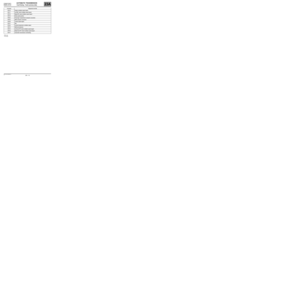 16
16 17
17 18
18 19
19 20
20 21
21 22
22 23
23 24
24 25
25 26
26 27
27 28
28 29
29 30
30 31
31 32
32 33
33 34
34 35
35 36
36 37
37 38
38 39
39 40
40 41
41 42
42 43
43 44
44 45
45 46
46 47
47 48
48 49
49 50
50 51
51 52
52 53
53 54
54 55
55 56
56 57
57 58
58 59
59 60
60 61
61 62
62 63
63 64
64 65
65 66
66 67
67 68
68 69
69 70
70 71
71 72
72 73
73 74
74 75
75 76
76 77
77 78
78 79
79 80
80 81
81 82
82 83
83 84
84 85
85 86
86 87
87 88
88 89
89 90
90 91
91 92
92 93
93 94
94 95
95 96
96 97
97 98
98 99
99 100
100 101
101 102
102 103
103 104
104 105
105 106
106 107
107 108
108 109
109 110
110 111
111 112
112 113
113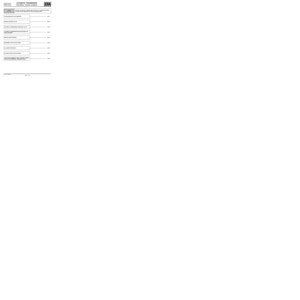 114
114 115
115 116
116 117
117 118
118 119
119 120
120 121
121 122
122 123
123 124
124 125
125 126
126 127
127

