Page 89 of 128

AUTOMATIC TRANSMISSION
Fault finding – Interpretation of statuses23A
23A-89V4 MR-372-J84-23A050$594.mif
SIEMENS TA2000
Vdiag No.: 10-11-15
ET025
SEQUENCE SOLENOID VALVE 5 CONTROL
NOTESThere must be no present or stored faults.
This status displays ACTIVE when the gear engaged is 1 and INACTIVE when other gears are engaged.
Disconnect the computer. Check the cleanliness and condition of the connectors.
Check the continuity of the following connections:
●Connection code 5DL between components 119 and 754.
If the connection is faulty and there is a repair procedure (see Technical Note 6015A, Electrical wiring repair,
Wiring: Precautions for repair), repair the wiring, otherwise replace it.
Measure the resistance of component 754 between the following connections:
●Connection code 5AU.
●Connection code 5DL.
The value should be 40 ΩΩ Ω Ω
± 2 ΩΩ Ω Ω
at approximately 20˚C.
If the connection or connections are faulty and there is a repair procedure (see Technical Note 6015A, Electrical
wiring repair, Wiring: Precautions for repair), repair the wiring, otherwise replace it.
If the resistance is greater than 50 Ω, check the wiring harness, computer connector and modular connector.
Reconnect the computer.
Activate the solenoid valves with command AC024 Actuator sequential control and measure the current in the
solenoid valves.
If the current is 250 mA, the solenoid valve is working properly.
If the current is weaker, check the computer connections and harness up to the solenoid valve.
If the status is still not correct, use the interpretation of fault DF088 EVS5 Sequence solenoid valve circuit.
If the fault is still present, replace the electric/hydraulic interface.
AFTER REPAIRRepeat the conformity check from the start.
Make sure that shifting up and down through each gear works properly.
DP0TA2000_V10_ET025/DP0TA2000_V11_ET025/DP0TA2000_V15_ET025
Page 90 of 128

AUTOMATIC TRANSMISSION
Fault finding – Interpretation of statuses23A
23A-90V4 MR-372-J84-23A050$594.mif
SIEMENS TA2000
Vdiag No.: 10-11-15
ET026
SEQUENCE SOLENOID VALVE 6 CONTROL
NOTESThere must be no present or stored faults.
This status displays INACTIVE with any gear engaged.
Disconnect the computer. Check the cleanliness and condition of the connectors.
Check the continuity of the following connections:
●Connection code 5DM between components 119 and 754.
If the connection is faulty and there is a repair procedure (see Technical Note 6015A, Electrical wiring repair,
Wiring: Precautions for repair), repair the wiring, otherwise replace it.
Measure the resistance of component 754 between the following connections:
The value should be 40 ΩΩ Ω Ω
± 2 ΩΩ Ω Ω
at approximately 20˚C.
If the connection or connections are faulty and there is a repair procedure (see Technical Note 6015A, Electrical
wiring repair, Wiring: Precautions for repair), repair the wiring, otherwise replace it.
If the resistance is greater than 50 Ω, check the wiring harness, computer connector and modular connector.
Reconnect the computer.
Activate the solenoid valves with command AC024 Actuator sequential control and measure the current
in the solenoid valves.
If the current is 250 mA, the solenoid valve is working properly.
If the current is weaker, check the computer connections and harness up to the solenoid valve.
If the status is still not correct, use the interpretation of fault DF112 EVS6 Sequence solenoid valve circuit.
If the fault is still present, replace the electric/hydraulic interface.
AFTER REPAIRRepeat the conformity check from the start.
Make sure that shifting up and down through each gear works properly.
DP0TA2000_V10_ET026/DP0TA2000_V11_ET026/DP0TA2000_V15_ET026
Page 91 of 128
AUTOMATIC TRANSMISSION
Fault finding – Interpretation of statuses23A
23A-91V4 MR-372-J84-23A050$594.mif
SIEMENS TA2000
Vdiag No.: 10-11-15
ET071
TORQUE CONVERTER
NOTESThere must be no present or stored faults.
This indicates the status of the torque converter.
The status should be ACTIVE when the vehicle is driven with a gear engaged.
The status should be INACTIVE when starting, changing gears, or if the vehicle is stopped.
If the status does not function as specified, apply the interpretation of fault DF016 Converter lockup solenoid
valve circuit.
If the fault is still present, contact your Techline.
AFTER REPAIRRepeat the conformity check from the start.
Make sure that shifting up and down through each gear works properly.
DP0TA2000_V10_ET071/DP0TA2000_V11_ET071/DP0TA2000_V15_ET071
Page 92 of 128
AUTOMATIC TRANSMISSION
Fault finding – Interpretation of statuses23A
23A-92V4 MR-372-J84-23A050$594.mif
SIEMENS TA2000
Vdiag No.: 10-11-15
ET097
MANUAL MODE
NOTESThere must be no present or stored faults.
This status indicates the gear lever position.
This status displays ACTIVE when the gear lever is in position M, M+ or M-.
This status displays INACTIVE when the gear lever is in positions P, R, N or D.
If the correct status is not displayed, use the interpretation of fault DF093 Manual sequential controls circuits.
If the fault is still present, replace the sequential lever module.
If the fault is still present, contact your Techline.
AFTER REPAIRRepeat the conformity check from the start.
Make sure that shifting up and down through each gear works properly.
DP0TA2000_V10_ET097/DP0TA2000_V11_ET097/DP0TA2000_V15_ET097
Page 93 of 128

AUTOMATIC TRANSMISSION
Fault finding – Interpretation of statuses23A
23A-93V4 MR-372-J84-23A050$594.mif
SIEMENS TA2000
Vdiag No.: 10-11-15
ET123
ET124
ET125
MULTIFUNCTION SWITCH S2
MULTIFUNCTION SWITCH S3
MULTIFUNCTION SWITCH S4
NOTESThere must be no present or stored faults.
Multifunction switch contact S1 is not connected on this model.
These statuses show the position of the multifunction switch for each gear lever position.
The switch status can be OPEN or CLOSED (see table below).
S2 S3 S4
POPEN CLOSED CLOSED
ROPEN OPEN OPEN
NCLOSED OPEN CLOSED
DCLOSED CLOSED OPEN
MCLOSED CLOSED OPEN
M+ CLOSED CLOSED OPEN
M- CLOSED CLOSED OPEN
If the correct status is not displayed, use the interpretation of fault DF009 Multifunction switch in prohibited
position.
If after these checks, statuses ET123, ET124 or ET125 are incorrect, replace the multifunction switch.
AFTER REPAIRRepeat the conformity check from the start.
Make sure that shifting up and down through each gear works properly.
DP0TA2000_V10_ET123/DP0TA2000_V11_ET123/DP0TA2000_V15_ET123/
DP0TA2000_V10_ET124/DP0TA2000_V11_ET124/DP0TA2000_V15_ET124/
DP0TA2000_V10_ET125/DP0TA2000_V11_ET125/DP0TA2000_V15_ET125
Page 94 of 128
AUTOMATIC TRANSMISSION
Fault finding – Interpretation of statuses23A
23A-94V4 MR-372-J84-23A050$594.mif
SIEMENS TA2000
Vdiag No.: 10-11-15
ET126
MULTIFUNCTION SWITCH P/N
NOTESThere must be no present or stored faults.
These indicate the status of the P/N multifunction switch contact for each gearshift position.
The switch status is "OPEN" or "CLOSED".
The status should be OPEN when the gear lever is in any position except P.
The status should be CLOSED when the gear lever is in position P.
If this status does not operate as indicated above, use the interpretation of fault DF054 Multifunction switch P/N
contact signal.
If the fault is still present, contact your Techline.
AFTER REPAIRRepeat the conformity check from the start.
Make sure that shifting up and down through each gear works properly.
DP0TA2000_V10_ET126/DP0TA2000_V11_ET126/DP0TA2000_V15_ET126
Page 95 of 128

AUTOMATIC TRANSMISSION
Fault finding – Interpretation of statuses23A
23A-95V4 MR-372-J84-23A050$594.mif
SIEMENS TA2000
Vdiag No.: 10-11-15
ET127
LOWER SEQUENTIAL LEVER SWITCH
NOTESThere must be no present or stored faults.
This indicates the status of the lower sequential lever switch.
This status displays ACTIVE with the gear lever in position M-.
This status displays INACTIVE with the gear lever in a position other than M-.
Check the sequential lever supply on the following connections:
●Check for + 12 V on connection AP43 of component 129.
●Check for the vehicle earth on connection N of component 129.
If the connection or connections are faulty and there is a repair procedure (see Technical Note 6015A, Electrical
wiring repair, Wiring: Precautions for repair), repair the wiring, otherwise replace it.
With the gear lever in position M, measure the voltage of the following connections:
●Check for the vehicle earth on connection 5H of component 129.
●Check for the vehicle earth on connection 5FM of component 129.
If the connection or connections are faulty and there is a repair procedure (see Technical Note 6015A, Electrical
wiring repair, Wiring: Precautions for repair), repair the wiring, otherwise replace it.
If any of the measured values is + 12 V, replace the sequential lever
If the values are 0 V, check that the selector lever positions match those displayed on the instrument panel.
Repair if necessary.
If the correct status is not displayed, use the interpretation of fault DF093 Manual sequential controls circuits.
If the fault is still present, contact the Techline.
AFTER REPAIRRepeat the conformity check from the start.
DP0TA2000_V10_ET128
Page 96 of 128

AUTOMATIC TRANSMISSION
Fault finding – Interpretation of statuses23A
23A-96V4 MR-372-J84-23A050$594.mif
SIEMENS TA2000
Vdiag No.: 10-11-15
ET128
UPPER SEQUENTIAL LEVER SWITCH
NOTESThere must be no present or stored faults.
This indicates the status of the lower sequential lever switch.
This status displays ACTIVE with the gear lever in position M+.
This status displays INACTIVE with the gear lever in a position other than M+.
Check the sequential lever supply on the following connections:
●Check for + 12 V on connection AP43 of component 129.
●Check for the vehicle earth on connection N of component 129.
If the connection or connections are faulty and there is a repair procedure (see Technical Note 6015A, Electrical
wiring repair, Wiring: Precautions for repair), repair the wiring, otherwise replace it.
With the gear lever in position M, measure the voltage of the following connections:
●Check for the vehicle earth on connection 5H of component 129.
●Check for the vehicle earth on connection 5FM of component 129.
If the connection or connections are faulty and there is a repair procedure (see Technical Note 6015A, Electrical
wiring repair, Wiring: Precautions for repair), repair the wiring, otherwise replace it.
If any of the measured values is + 12 V, replace the sequential lever
If the values are 0 V, check that the selector lever positions match those displayed on the instrument panel.
If the correct status is not displayed, use the interpretation of fault DF093 Manual sequential controls circuits.
If the fault is still present, contact the Techline.
AFTER REPAIRRepeat the conformity check from the start.
DP0TA2000_V10_ET128/DP0TA2000_V11_ET128/DP0TA2000_V15_ET128
 1
1 2
2 3
3 4
4 5
5 6
6 7
7 8
8 9
9 10
10 11
11 12
12 13
13 14
14 15
15 16
16 17
17 18
18 19
19 20
20 21
21 22
22 23
23 24
24 25
25 26
26 27
27 28
28 29
29 30
30 31
31 32
32 33
33 34
34 35
35 36
36 37
37 38
38 39
39 40
40 41
41 42
42 43
43 44
44 45
45 46
46 47
47 48
48 49
49 50
50 51
51 52
52 53
53 54
54 55
55 56
56 57
57 58
58 59
59 60
60 61
61 62
62 63
63 64
64 65
65 66
66 67
67 68
68 69
69 70
70 71
71 72
72 73
73 74
74 75
75 76
76 77
77 78
78 79
79 80
80 81
81 82
82 83
83 84
84 85
85 86
86 87
87 88
88 89
89 90
90 91
91 92
92 93
93 94
94 95
95 96
96 97
97 98
98 99
99 100
100 101
101 102
102 103
103 104
104 105
105 106
106 107
107 108
108 109
109 110
110 111
111 112
112 113
113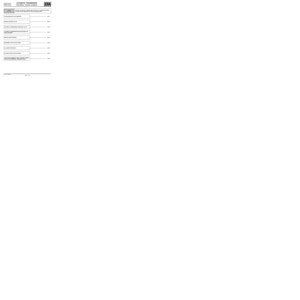 114
114 115
115 116
116 117
117 118
118 119
119 120
120 121
121 122
122 123
123 124
124 125
125 126
126 127
127

