2008 RENAULT SCENIC display
[x] Cancel search: displayPage 3 of 128

AUTOMATIC TRANSMISSION
Fault finding – Introduction23A
23A - 3V4 MR-372-J84-23A050$066.mif
SIEMENS TA2000
Vdiag No.: 10-11-15
To cut off + after ignition, proceed as follows:
–Disconnect the diagnostic tool.
–Press the Start button twice briefly (less than 3 seconds).
–Ensure that the + after ignition feed has been cut off by checking that the computer indicator lights on the
instrument panel have gone out.
Faults
Faults are declared either present or stored (depending on whether they appeared in a certain context and
disappeared since, or whether they remain present but have not been diagnosed within the current context).
The present or stored status of faults should be taken into consideration when the diagnostic tool is switched on
after the + after ignition feed (without any system components being active).
For a present fault, apply the procedure described in the Interpretation of faults section.
For a stored fault, note the faults displayed and apply the instructions in the Notes section.
If the fault is confirmed when the instructions in the Notes section are applied, the fault is present. Deal with the fault
If the fault is not confirmed, check:
–the electrical lines which correspond to the fault,
–the connectors for these lines (for oxidation, bent pins, etc.),
–the resistance of the component detected as faulty,
–the condition of the wires (melted or split insulation, wear).
Conformity check
The aim of the conformity check is to check data that does not produce a fault on the diagnostic tool because the
data is inconsistent. Therefore, this stage is used to:
–carry out fault finding on faults that do not have a fault display, and which may correspond to a customer
complaint.
–check that the system is operating correctly and that there is no risk of a fault recurring after repairs.
This section gives the fault finding procedures for statuses and parameters and the conditions for checking them.
If a status is not behaving normally or a parameter is outside the permitted tolerance values, consult the
corresponding fault finding page.
Customer complaints - Fault finding chart
If the test with the diagnostic tool is OK but the customer complaint is still present, the fault should be processed by
customer complaint. Note:
The left and right-hand xenon bulb computers are supplied when the dipped headlights are lit.
Therefore fault finding can only be carried out on them after the ignition has been switched on in fault finding mode
(forced + after ignition feed) and the dipped headlights have been switched on.
A synopsis of the general procedure to follow is provided on the following page in the form of a flow chart.
Page 10 of 128

AUTOMATIC TRANSMISSION
Fault finding – System operation23A
23A-10V4 MR-372-J84-23A050$132.mif
SIEMENS TA2000
Vdiag No.: 10-11-15
COMPUTER INPUTS AND OUTPUTS
INPUTS OUTPUTS
Diagnostic socket
Automatic
transmission
computer
Solenoid valve control
+ battery feed
+ after ignition feed + warning lights display
Intersystem signals + diagnostic
socketIntersystem signal + diagnostic
socket
Driver actions (brake light switch,
gear selector, multifunction
switch)Gear lever lock
AUTO sensors (turbine speed, oil
pressure, oil temperature)Reversing lights
Earth
Wire connection
Multiplexed connections
Page 13 of 128

AUTOMATIC TRANSMISSION
Fault finding – Replacement of components23A
23A - 13V4 MR-372-J84-23A050$198.mif
SIEMENS TA2000
Vdiag No.: 10-11-15
For SCENIC II only
Reading automatic transmission configuration
The read-configuration commands (LCXXX) are used to display the current computer configuration in relation to the
equipment installed in the vehicle.
Writing automatic transmission configuration
The write-configuration commands (CFXXX) are used to configure the computer for the equipment installed in the
vehicle.
These three settings are important because they optimise transmission operation for the vehicle. If they are not
entered properly, automatic transmission operation may be impaired.Configuration reading Configuration
LC014 Engine torque control function WITH/WITHOUT
LC015 Electronic stability control WITH/WITHOUT
LC017 Shift lock connection fault finding WITH/WITHOUT
Configuration reading Configuration
CF322 Engine torque control function WITH/WITHOUT
CF314 Electronic stability program (ESP) WITH/WITHOUT
CF325 Shift lock connection fault finding WITH/WITHOUT
Page 15 of 128

AUTOMATIC TRANSMISSION
Fault finding – Fault summary table23A
23A - 15V4 MR-372-J84-23A050$264.mif
SIEMENS TA2000
Vdiag No.: 10-11-15AUTOMATIC TRANSMISSION
Fault finding – Fault summary table
* EVS: Sequence solenoid valvesTool fault Diagnostic tool title
DF002 Computer
DF003 Analogue sensor feed
DF005 Oil pressure sensor circuit
DF009 Multifunction switch prohibited position
DF012 Solenoid valve feed
DF016 Lockup solenoid valve circuit
DF017 Exchanger flow rate solenoid valve circuit
DF018 Lockup slip
DF023 Gearbox oil temperature sensor circuit
DF029 Multifunction switch in unstable position
DF036 Pressure regulating solenoid valve circuit
DF038 Turbine speed sensor circuit
DF048 Vehicle speed signal
DF049 Pressure regulation
DF055 Injection →→ → →
automatic transmission connection
DF064 Display circuit
DF085 EVS*1 sequence solenoid valve circuit
DF086 EVS*2 sequence solenoid valve circuit
DF087 EVS*3 sequence solenoid valve circuit
DF088 EVS*5 sequence solenoid valve circuit
DF089 EVS*4 sequence solenoid valve circuit
DF093 Sequential gear lever circuit
DF095 Shift lock electromagnet circuit
DF109 Engine torque multiplex signal
DF112 *EVS6* sequence solenoid valve circuit
DF114 Pedal position multiplex signal
MR-372-J84-23A050$264.mif
Page 20 of 128

AUTOMATIC TRANSMISSION
Fault finding – Interpretation of faults23A
23A-20V4 MR-372-J84-23A050$330.mif
SIEMENS TA2000
Vdiag No.: 10-11-15
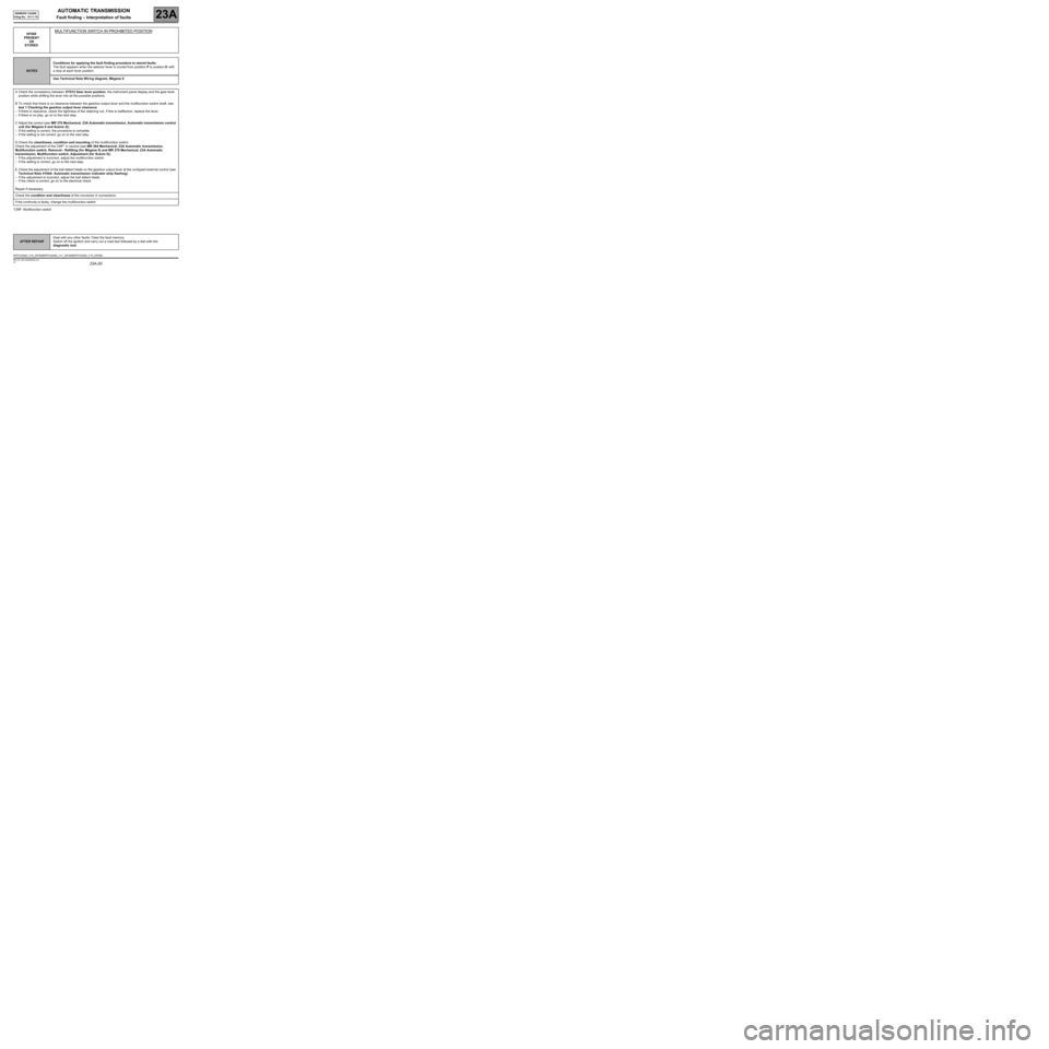
*CMF: Multifunction switchDF009
PRESENT
OR
STORED
MULTIFUNCTION SWITCH IN PROHIBITED POSITION
NOTESConditions for applying the fault finding procedure to stored faults:
The fault appears when the selector lever is moved from position P to position D with
a stop at each lever position.
Use Technical Note Wiring diagram, Mégane II
ACheck the consistency between: ET012 Gear lever position, the instrument panel display and the gear lever
position while shifting the lever into all the possible positions.
BTo check that there is no clearance between the gearbox output lever and the multifunction switch shaft, see
test 1 Checking the gearbox output lever clearance
–If there is clearance, check the tightness of the retaining nut. If this is ineffective, replace the lever.
–If there is no play, go on to the next step.
CAdjust the control (see MR 370 Mechanical, 23A Automatic transmission, Automatic transmission control
unit (for Mégane II and Scénic II)).
–If the setting is correct, the procedure is complete.
–If the setting is not correct, go on to the next step.
DCheck the cleanliness, condition and mounting of the multifunction switch.
Check the adjustment of the CMF* in neutral (see MR 364 Mechanical, 23A Automatic transmission,
Multifunction switch, Removal - Refitting (for Mégane II) and MR 370 Mechanical, 23A Automatic
transmission, Multifunction switch, Adjustment (for Scénic II)).
–If the adjustment is incorrect, adjust the multifunction switch.
–If the setting is correct, go on to the next step.
ECheck the adjustment of the ball detent blade on the gearbox output lever at the unclipped external control (see
Technical Note 4194A: Automatic transmission indicator strip flashing):
–If the adjustment is incorrect, adjust the ball detent blade.
–If the check is correct, go on to the electrical check.
Repair if necessary.
Check the condition and cleanliness of the connector A connections.
If the continuity is faulty, change the multifunction switch.
AFTER REPAIRDeal with any other faults. Clear the fault memory.
Switch off the ignition and carry out a road test followed by a test with the
diagnostic tool.
DP0TA2000_V10_DF009/DP0TA2000_V11_DF009/DP0TA2000_V15_DF009
Page 29 of 128

AUTOMATIC TRANSMISSION
Fault finding – Interpretation of faults23A
23A-29V4 MR-372-J84-23A050$330.mif
SIEMENS TA2000
Vdiag No.: 10-11-15
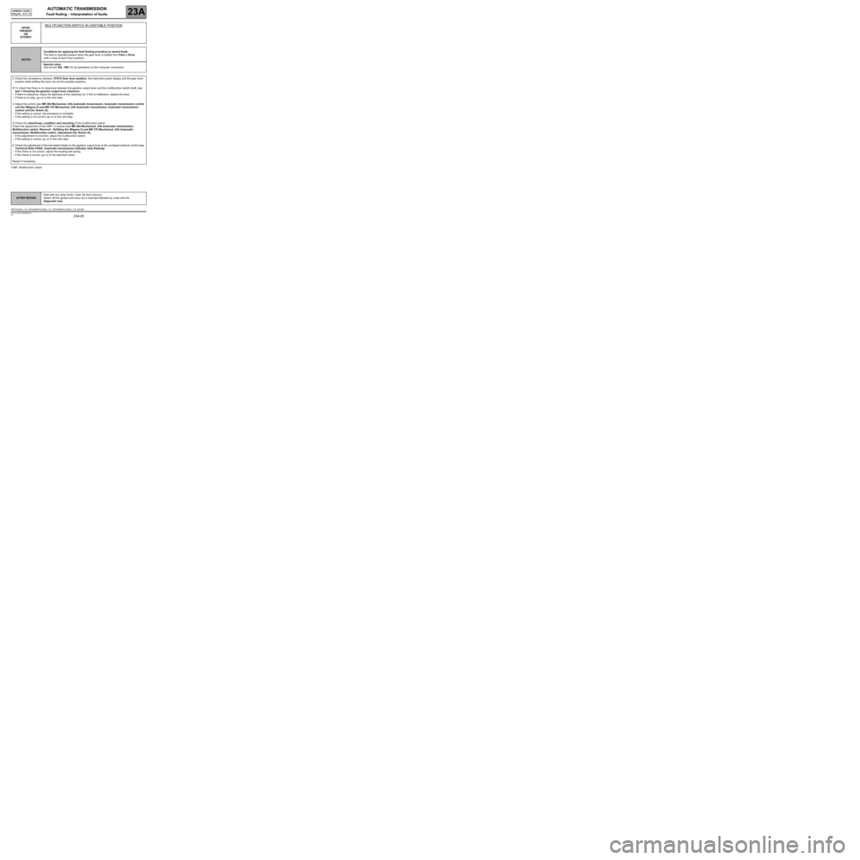
*CMF: Multifunction switchDF029
PRESENT
OR
STORED
MULTIFUNCTION SWITCH IN UNSTABLE POSITION
NOTESConditions for applying the fault finding procedure to stored faults:
The fault is reported present when the gear lever is shifted from Park to Drive
(with a stop at each lever position).
Special notes:
Use bornier Elé. 1681 for all operations on the computer connectors.
ACheck the consistency between: ET012 Gear lever position, the instrument panel display and the gear lever
position while shifting the lever into all the possible positions.
BTo check that there is no clearance between the gearbox output lever and the multifunction switch shaft, see
test 1 Checking the gearbox output lever clearance
–If there is clearance, check the tightness of the retaining nut. If this is ineffective, replace the lever.
–If there is no play, go on to the next step.
CAdjust the control (see MR 364 Mechanical, 23A Automatic transmission, Automatic transmission control
unit (for Mégane II) and MR 370 Mechanical, 23A Automatic transmission, Automatic transmission
control unit (for Scénic II)).
–If the setting is correct, the procedure is complete.
–If the setting is not correct, go on to the next step.
DCheck the cleanliness, condition and mounting of the multifunction switch.
Check the adjustment of the CMF* in neutral (see MR 364 Mechanical, 23A Automatic transmission,
Multifunction switch, Removal - Refitting (for Mégane II) and MR 370 Mechanical, 23A Automatic
transmission, Multifunction switch, Adjustment (for Scénic II)).
–If the adjustment is incorrect, adjust the multifunction switch.
–If the setting is correct, go on to the next step.
ECheck the adjustment of the ball detent blade on the gearbox output lever at the unclipped external control (see
Technical Note 4194A: Automatic transmission indicator strip flashing):
–If the check is not correct, adjust the locating ball spring.
–If the check is correct, go on to the electrical check.
Repair if necessary.
AFTER REPAIRDeal with any other faults. Clear the fault memory.
Switch off the ignition and carry out a road test followed by a test with the
diagnostic tool.
DP0TA2000_V10_DF029/DP0TA2000_V11_DF029/DP0TA2000_V15_DF029
Page 38 of 128

AUTOMATIC TRANSMISSION
Fault finding – Interpretation of faults23A
23A-38V4 MR-372-J84-23A050$330.mif
SIEMENS TA2000
Vdiag No.: 10-11-15
DF064
PRESENT
OR
STOREDDISPLAY CIRCUIT
CO.0 : Open circuit or short circuit to earth
NOTESNone.
Disconnect the battery.
Check the cleanness and condition of the gear lever display connections.
Disconnect the computer.
Check the cleanliness and condition of the connections.
Use the universal bornier Elé. 1681 to check the insulation, continuity and the absence of interference
resistance on the following connection:
●Connection code 5CQ between components 119 and 1129.
If the connection is faulty and there is a repair procedure (see Technical Note 6015A, Electrical wiring repair,
Wiring: Precautions for repair), repair the wiring, otherwise replace it.
If the fault is still present, contact the Techline.
AFTER REPAIRDeal with any other faults. Clear the fault memory.
Switch off the ignition and carry out a road test followed by a test with the
diagnostic tool.
DP0TA2000_V10_DF064/DP0TA2000_V11_DF064/DP0TA2000_V15_DF064
Page 62 of 128

AUTOMATIC TRANSMISSION
Fault finding – Conformity check23A
23A - 62V4 MR-372-J84-23A050$462.mif
SIEMENS TA2000
Vdiag No.: 10-11-15
MAIN SCREEN
NOTESOnly carry out this conformity check after a complete check with the diagnostic tool
(no present or stored faults).
Application conditions: engine stopped, ignition on.
The values indicated in this conformity check are given as examples.
Order FunctionParameter or Status
checked or ActionDisplay and Notes Fault finding
1Engine
speedPR006:Engine speed0 rpmIn the event of a
fault, consult the
interpretation of
this parameter.
2Gear
selector
positionET012:Gear
selector
position "P" if selector in position "P"
"N" if selector in position "N"
"R" if selector in position "R"
"D" if selector in position "D"
"M" if selector in position "M"
"M+" if selector in position "M+"
"M-" if selector in position "M-"In the event of a
fault, refer to the
interpretation of
this status.
3GearET013:Gear
engagedN for position N
"1" for 1
st unlocked
"2" for 2nd unlocked
"R" for reverse gear positionIn the event of a
fault, refer to the
interpretation of
this status.
4Power
supplyPR008:Computer
feed voltage10.5 < X < 16In the event of a
fault, consult the
interpretation of
this parameter.