2008 NISSAN TIIDA page 71
[x] Cancel search: page 71Page 1192 of 2771
EC-118
< SERVICE INFORMATION >
TROUBLE DIAGNOSIS
*: Leaving cooling fan OFF with CONSULT-II while engine is running may cause the engine to overheat.
DTC & SRT CONFIRMATION MODE
SRT STATUS Mode
For details, refer to EC-47, "Emission-related Diagnostic Information".
SRT WORK SUPPORT Mode
This mode enables a technician to drive a vehicle to set the SRT while monitoring the SRT status.
DTC WORK SUPPORT Mode
*: DTC P1442 and P1456 does not apply to C11 models but appears in DTC Work Support Mode screens.
REAL TIME DIAGNOSIS IN DATA MONITOR MODE (RECORDING VEHICLE DATA)
Description
CONSULT-II has two kinds of triggers and they can be selected by touching “SETTING” in “DATA MONITOR”
mode.
1. “AUTO TRIG” (Automatic trigger):
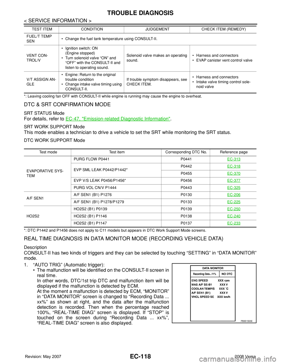
• The malfunction will be identified on the CONSULT-II screen in
real time.
In other words, DTC/1st trip DTC and malfunction item will be
displayed if the malfunction is detected by ECM.
At the moment a malfunction is detected by ECM, “MONITOR”
in “DATA MONITOR” screen is changed to “Recording Data ...
xx%” as shown at right, and the data after the malfunction
detection is recorded. Then when the percentage reached
100%, “REAL-TIME DIAG” screen is displayed. If “STOP” is
touched on the screen during “Recording Data ... xx%”,
“REAL-TIME DIAG” screen is also displayed.
FUEL/T TEMP
SEN• Change the fuel tank temperature using CONSULT-II.
VENT CON-
TROL/V•Ignition switch: ON
(Engine stopped)
• Turn solenoid valve “ON” and
“OFF” with the CONSULT-II and
listen to operating sound.Solenoid valve makes an operating
sound.• Harness and connectors
• EVAP canister vent control valve
V/T ASSIGN AN-
GLE• Engine: Return to the original
trouble condition
• Change intake valve timing using
CONSULT-II.If trouble symptom disappears, see
CHECK ITEM.• Harness and connectors
• Intake valve timing control sole-
noid valve TEST ITEM CONDITION JUDGEMENT CHECK ITEM (REMEDY)
Test mode Test item Corresponding DTC No. Reference page
EVAPORATIVE SYS-
TEMPURG FLOW P0441 P0441EC-313
EVP SML LEAK P0442/P1442*P0442EC-318P0455EC-370
EVP V/S LEAK P0456/P1456* P0456EC-377
PURG VOL CN/V P1444 P0443EC-325
A/F SEN1A/F SEN1 (B1) P1276 P0130EC-206A/F SEN1 (B1) P1278/P1279 P0133EC-225
HO2S2HO2S2 (B1) P0139 P0139EC-250HO2S2 (B1) P1146 P0138EC-240
HO2S2 (B1) P1147 P0137EC-233
PBIB1593E
Page 1498 of 2771
EC-424
< SERVICE INFORMATION >
DTC P1217 ENGINE OVER TEMPERATURE
OK >> GO TO 6.
NG >> Replace cooling fan motor.
6.CHECK INTERMITTENT INCIDENT
Perform EC-136
.
OK or NG
OK >> Replace IPDM E/R. Refer to PG-26, "Removal and Installation of IPDM E/R".
NG >> Repair or replace harness or connector.
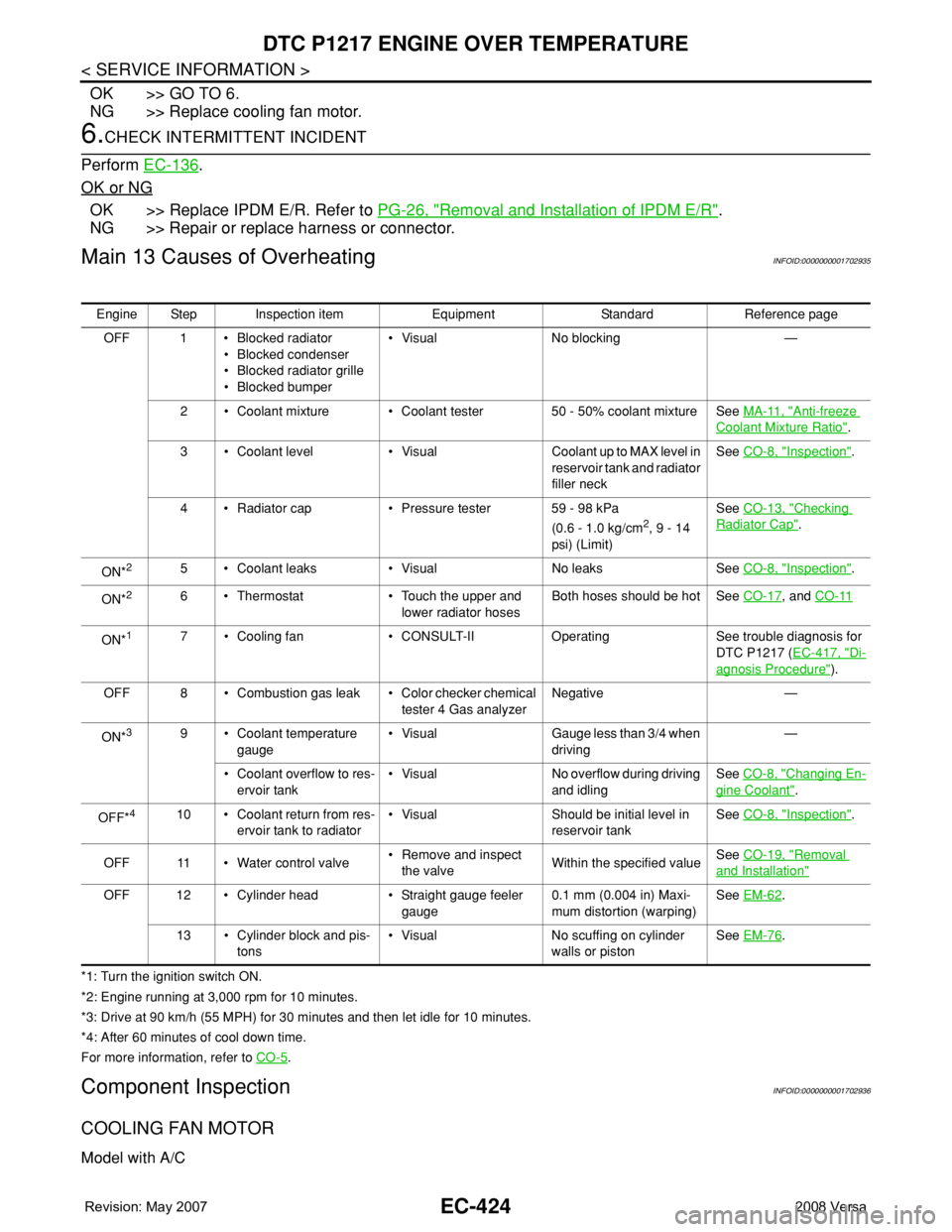
Main 13 Causes of OverheatingINFOID:0000000001702935
*1: Turn the ignition switch ON.
*2: Engine running at 3,000 rpm for 10 minutes.
*3: Drive at 90 km/h (55 MPH) for 30 minutes and then let idle for 10 minutes.
*4: After 60 minutes of cool down time.
For more information, refer to CO-5
.
Component InspectionINFOID:0000000001702936
COOLING FAN MOTOR
Model with A/C
Engine Step Inspection item Equipment Standard Reference page
OFF 1 • Blocked radiator
• Blocked condenser
• Blocked radiator grille
• Blocked bumper• Visual No blocking —
2 • Coolant mixture • Coolant tester 50 - 50% coolant mixture See MA-11, "
Anti-freeze
Coolant Mixture Ratio".
3 • Coolant level • Visual Coolant up to MAX level in
reservoir tank and radiator
filler neckSee CO-8, "
Inspection".
4 • Radiator cap • Pressure tester 59 - 98 kPa
(0.6 - 1.0 kg/cm
2, 9 - 14
psi) (Limit)See CO-13, "
Checking
Radiator Cap".
ON*
25 • Coolant leaks • Visual No leaks See CO-8, "Inspection".
ON*
26 • Thermostat • Touch the upper and
lower radiator hosesBoth hoses should be hot See CO-17, and CO-11
ON*17 • Cooling fan • CONSULT-II Operating See trouble diagnosis for
DTC P1217 (EC-417, "
Di-
agnosis Procedure").
OFF 8 • Combustion gas leak • Color checker chemical
tester 4 Gas analyzerNegative —
ON*
39 • Coolant temperature
gauge• Visual Gauge less than 3/4 when
driving—
• Coolant overflow to res-
ervoir tank• Visual No overflow during driving
and idlingSee CO-8, "
Changing En-
gine Coolant".
OFF*
410 • Coolant return from res-
ervoir tank to radiator• Visual Should be initial level in
reservoir tankSee CO-8, "Inspection".
OFF 11 • Water control valve• Remove and inspect
the valveWithin the specified valueSee CO-19, "
Removal
and Installation"
OFF 12 • Cylinder head • Straight gauge feeler
gauge0.1 mm (0.004 in) Maxi-
mum distortion (warping)See EM-62.
13 • Cylinder block and pis-
tons• Visual No scuffing on cylinder
walls or pistonSee EM-76
.
Page 1689 of 2771
EM-12
< SERVICE INFORMATION >
NOISE, VIBRATION AND HARSHNESS (NVH) TROUBLESHOOTING
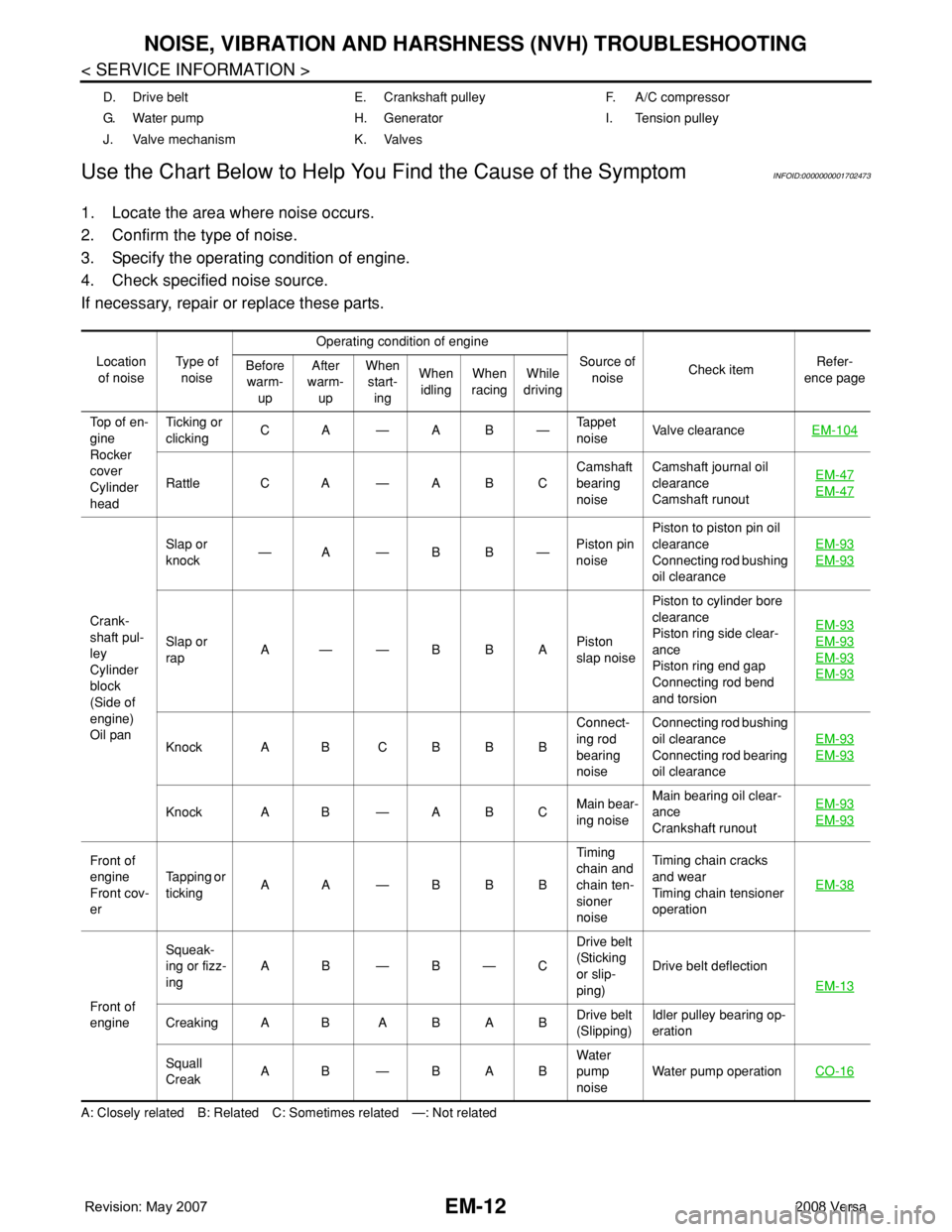
Use the Chart Below to Help You Find the Cause of the Symptom
INFOID:0000000001702473
1. Locate the area where noise occurs.
2. Confirm the type of noise.
3. Specify the operating condition of engine.
4. Check specified noise source.
If necessary, repair or replace these parts.
A: Closely related B: Related C: Sometimes related —: Not relatedD. Drive belt E. Crankshaft pulley F. A/C compressor
G. Water pump H. Generator I. Tension pulley
J. Valve mechanism K. Valves
Location
of noiseTyp e of
noiseOperating condition of engine
Source of
noiseCheck itemRefer-
ence page Before
warm-
upAfter
warm-
upWhen
start-
ingWhen
idlingWhen
racingWhile
driving
Top of en-
gine
Rocker
cover
Cylinder
headTicking or
clickingCA—AB—Tappet
noiseValve clearanceEM-104
Rattle C A — A B CCamshaft
bearing
noiseCamshaft journal oil
clearance
Camshaft runoutEM-47EM-47
Crank-
shaft pul-
ley
Cylinder
block
(Side of
engine)
Oil panSlap or
knock—A—BB—Piston pin
noisePiston to piston pin oil
clearance
Connecting rod bushing
oil clearanceEM-93
EM-93
Slap or
rapA——BBAPiston
slap noisePiston to cylinder bore
clearance
Piston ring side clear-
ance
Piston ring end gap
Connecting rod bend
and torsionEM-93EM-93
EM-93
EM-93
Knock A B C B B BConnect-
ing rod
bearing
noiseConnecting rod bushing
oil clearance
Connecting rod bearing
oil clearanceEM-93EM-93
Knock A B — A B CMain bear-
ing noiseMain bearing oil clear-
ance
Crankshaft runoutEM-93EM-93
Front of
engine
Front cov-
erTapping or
tickingAA—BBBTiming
chain and
chain ten-
sioner
noiseTiming chain cracks
and wear
Timing chain tensioner
operationEM-38
Front of
engineSqueak-
ing or fizz-
ingAB—B—CDrive belt
(Sticking
or slip-
ping)Drive belt deflection
EM-13
Creaking A B A B A BDrive belt
(Slipping)Idler pulley bearing op-
eration
Squall
CreakAB—BABWater
pump
noiseWater pump operationCO-16
Page 1800 of 2771
FAX-4
< SERVICE INFORMATION >
NOISE, VIBRATION AND HARSHNESS (NVH) TROUBLESHOOTING
NOISE, VIBRATION AND HARSHNESS (NVH) TROUBLESHOOTING
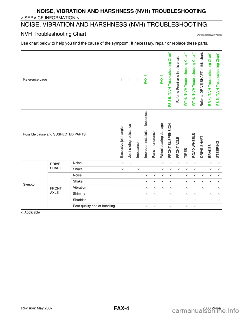
NVH Troubleshooting ChartINFOID:0000000001703700
Use chart below to help you find the cause of the symptom. If necessary, repair or replace these parts.
×: ApplicableReference page
—
—
—
FAX-5—
FAX-5
FSU-5, "
NVH Troubleshooting Chart
"
Refer to Front axle in this chart.
WT-4, "
NVH Troubleshooting Chart
"
WT-4, "
NVH Troubleshooting Chart
"
Refer to DRIVE SHAFT in this chart.
BR-4, "
NVH Troubleshooting Chart
"
PS-5, "
NVH Troubleshooting Chart
"
Possible cause and SUSPECTED PARTS
Excessive joint angle
Joint sliding resistance
Imbalance
Improper installation, looseness
Parts interference
Wheel bearing damage
FRONT SUSPENSION
FRONT AXLE
TIRES
ROAD WHEELS
DRIVE SHAFT
BRAKES
STEERING
SymptomDRIVE
SHAFTNoise×× ××××× ××
Shake× × ××××× ××
FRONT
AXLENoise×××× ×××××
Shake×××× ×××××
Vibration×××××××
Shimmy×××××××
Shudder× × ×× ××
Poor quality ride or handling×××××
Page 1839 of 2771
NOISE, VIBRATION AND HARSHNESS (NVH) TROUBLESHOOTING
FSU-5
< SERVICE INFORMATION >
C
D
F
G
H
I
J
K
L
MA
B
FSU
N
O
P
NOISE, VIBRATION AND HARSHNESS (NVH) TROUBLESHOOTING
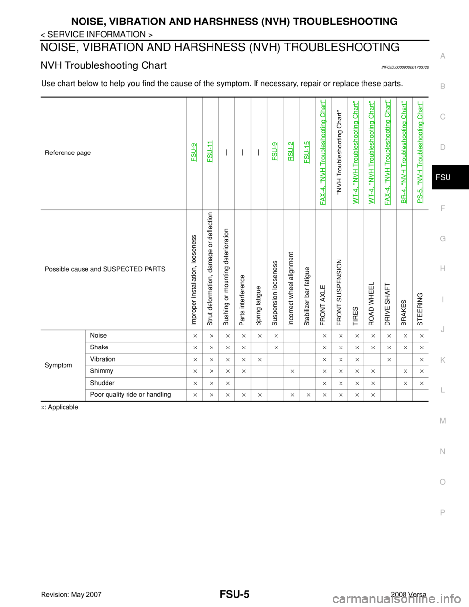
NVH Troubleshooting ChartINFOID:0000000001703720
Use chart below to help you find the cause of the symptom. If necessary, repair or replace these parts.
×: ApplicableReference page
FSU-9 FSU-11
—
—
—
FSU-9 RSU-2FSU-15
FAX-4, "
NVH Troubleshooting Chart
"
"NVH Troubleshooting Chart"
WT-4, "
NVH Troubleshooting Chart
"
WT-4, "
NVH Troubleshooting Chart
"
FAX-4, "
NVH Troubleshooting Chart
"
BR-4, "
NVH Troubleshooting Chart
"
PS-5, "
NVH Troubleshooting Chart
"
Possible cause and SUSPECTED PARTS
Improper installation, looseness
Strut deformation, damage or deflection
Bushing or mounting deterioration
Parts interference
Spring fatigue
Suspension looseness
Incorrect wheel alignment
Stabilizer bar fatigue
FRONT AXLE
FRONT SUSPENSION
TIRES
ROAD WHEEL
DRIVE SHAFT
BRAKES
STEERING
SymptomNoise×××××× ×××××××
Shake×××× × ×××××××
Vibration××××× ××× × ×
Shimmy×××× × ×××× ××
Shudder××× ×××× ××
Poor quality ride or handling××××× ××××××
Page 1858 of 2771
HOW TO USE THIS MANUAL
GI-7
< SERVICE INFORMATION >
C
D
E
F
G
H
I
J
K
L
MB
GI
N
O
PHOW TO USE THIS MANUAL
DescriptionINFOID:0000000001702431
This volume explains “Removal, Disassembly, Installation, Inspection and Adjustment” and “Trouble Diag-
noses”.
Te r m sINFOID:0000000001702432
• The captions WARNING and CAUTION warn you of steps that must be followed to prevent personal injury
and/or damage to some part of the vehicle.
WARNING indicates the possibility of personal injury if instructions are not followed.
CAUTION indicates the possibility of component damage if instructions are not followed.
BOLD TYPED STATEMENTS except WARNING and CAUTION give you helpful information.
Standard value:Tolerance at inspection and adjustment.
Limit value:The maximum or minimum limit value that should not be exceeded at inspection and adjustment.
UnitsINFOID:0000000001702433
• The UNITS given in this manual are primarily expressed as the SI UNIT (International System of Unit), and
alternatively expressed in the metric system and in the yard/pound system.
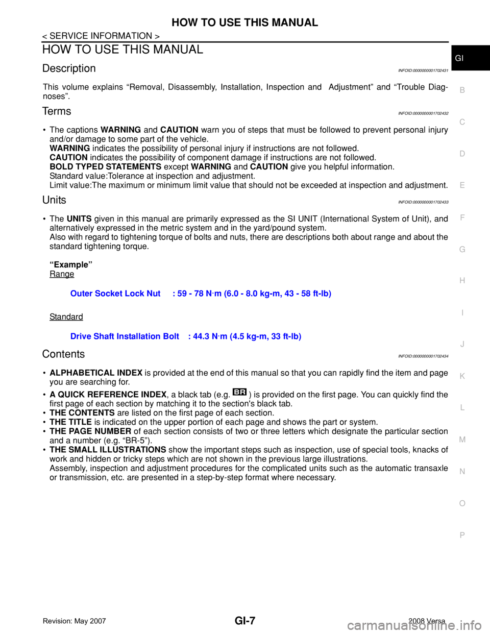
Also with regard to tightening torque of bolts and nuts, there are descriptions both about range and about the
standard tightening torque.
“Example”
Range
Standard
ContentsINFOID:0000000001702434
•ALPHABETICAL INDEX is provided at the end of this manual so that you can rapidly find the item and page
you are searching for.
•A QUICK REFERENCE INDEX, a black tab (e.g. ) is provided on the first page. You can quickly find the
first page of each section by matching it to the section's black tab.
•THE CONTENTS are listed on the first page of each section.
•THE TITLE is indicated on the upper portion of each page and shows the part or system.
•THE PAGE NUMBER of each section consists of two or three letters which designate the particular section
and a number (e.g. “BR-5”).
•THE SMALL ILLUSTRATIONS show the important steps such as inspection, use of special tools, knacks of
work and hidden or tricky steps which are not shown in the previous large illustrations.
Assembly, inspection and adjustment procedures for the complicated units such as the automatic transaxle
or transmission, etc. are presented in a step-by-step format where necessary. Outer Socket Lock Nut : 59 - 78 N·m (6.0 - 8.0 kg-m, 43 - 58 ft-lb)
Drive Shaft Installation Bolt: 44.3 N·m (4.5 kg-m, 33 ft-lb)
Page 1867 of 2771
GI-16
< SERVICE INFORMATION >
HOW TO USE THIS MANUAL
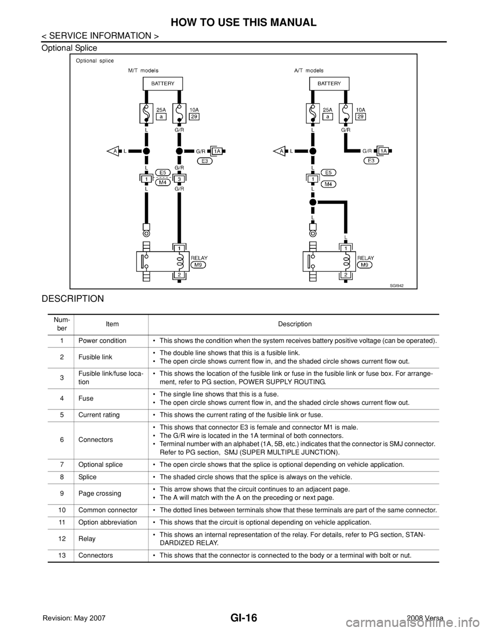
Optional Splice
DESCRIPTION
SGI942
Num-
berItem Description
1 Power condition • This shows the condition when the system receives battery positive voltage (can be operated).
2Fusible link• The double line shows that this is a fusible link.
• The open circle shows current flow in, and the shaded circle shows current flow out.
3Fusible link/fuse loca-
tion• This shows the location of the fusible link or fuse in the fusible link or fuse box. For arrange-
ment, refer to PG section, POWER SUPPLY ROUTING.
4Fuse• The single line shows that this is a fuse.
• The open circle shows current flow in, and the shaded circle shows current flow out.
5 Current rating • This shows the current rating of the fusible link or fuse.
6 Connectors• This shows that connector E3 is female and connector M1 is male.
• The G/R wire is located in the 1A terminal of both connectors.
• Terminal number with an alphabet (1A, 5B, etc.) indicates that the connector is SMJ connector.
Refer to PG section, SMJ (SUPER MULTIPLE JUNCTION).
7 Optional splice • The open circle shows that the splice is optional depending on vehicle application.
8 Splice • The shaded circle shows that the splice is always on the vehicle.
9 Page crossing• This arrow shows that the circuit continues to an adjacent page.
• The A will match with the A on the preceding or next page.
10 Common connector • The dotted lines between terminals show that these terminals are part of the same connector.
11 Option abbreviation • This shows that the circuit is optional depending on vehicle application.
12 Relay• This shows an internal representation of the relay. For details, refer to PG section, STAN-
DARDIZED RELAY.
13 Connectors • This shows that the connector is connected to the body or a terminal with bolt or nut.
Page 1868 of 2771
HOW TO USE THIS MANUAL
GI-17
< SERVICE INFORMATION >
C
D
E
F
G
H
I
J
K
L
MB
GI
N
O
P
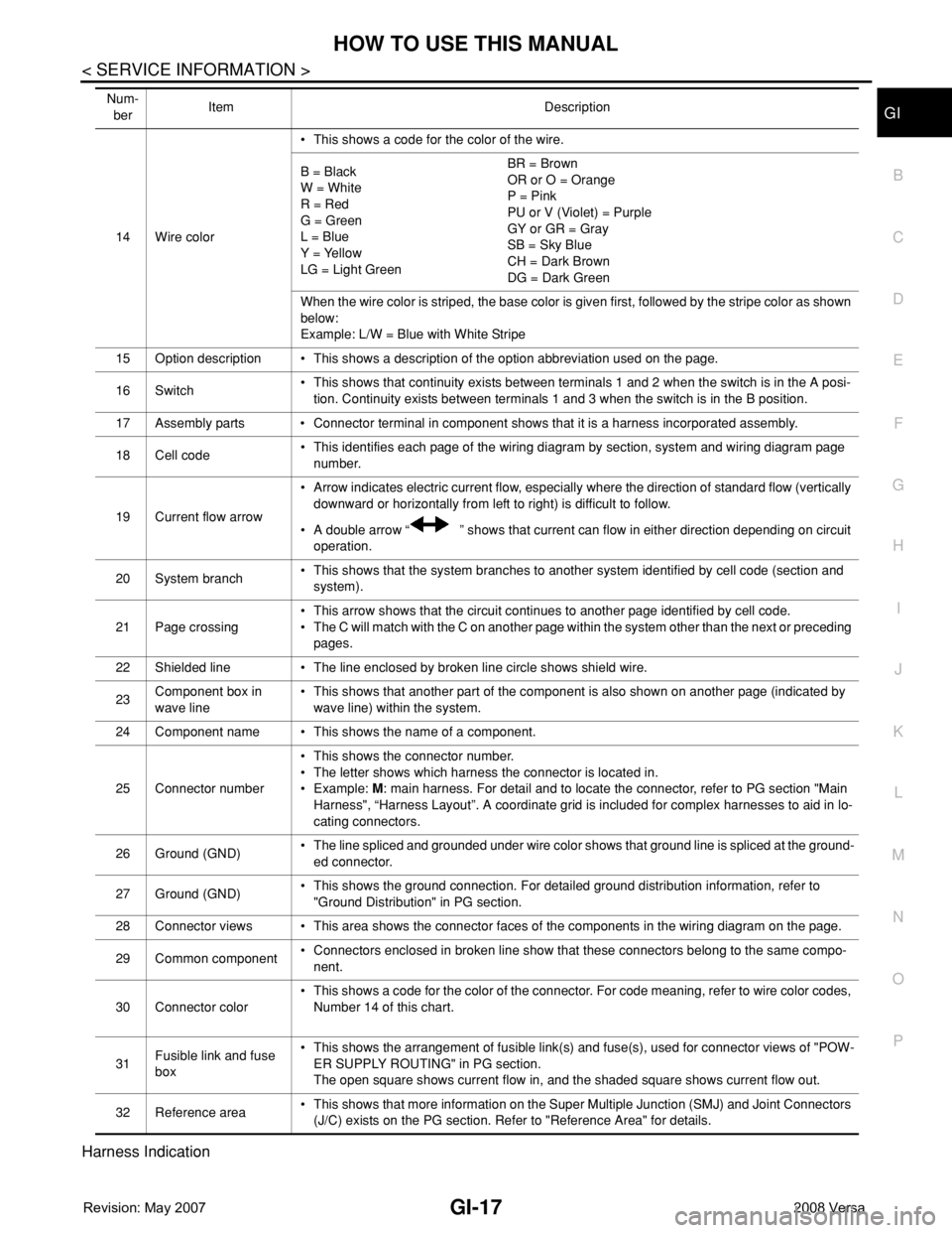
Harness Indication
14 Wire color• This shows a code for the color of the wire.
B = Black
W = White
R = Red
G = Green
L = Blue
Y = Yellow
LG = Light GreenBR = Brown
OR or O = Orange
P = Pink
PU or V (Violet) = Purple
GY or GR = Gray
SB = Sky Blue
CH = Dark Brown
DG = Dark Green
When the wire color is striped, the base color is given first, followed by the stripe color as shown
below:
Example: L/W = Blue with White Stripe
15 Option description • This shows a description of the option abbreviation used on the page.
16 Switch• This shows that continuity exists between terminals 1 and 2 when the switch is in the A posi-
tion. Continuity exists between terminals 1 and 3 when the switch is in the B position.
17 Assembly parts • Connector terminal in component shows that it is a harness incorporated assembly.
18 Cell code• This identifies each page of the wiring diagram by section, system and wiring diagram page
number.
19 Current flow arrow• Arrow indicates electric current flow, especially where the direction of standard flow (vertically
downward or horizontally from left to right) is difficult to follow.
• A double arrow “ ” shows that current can flow in either direction depending on circuit
operation.
20 System branch• This shows that the system branches to another system identified by cell code (section and
system).
21 Page crossing• This arrow shows that the circuit continues to another page identified by cell code.
• The C will match with the C on another page within the system other than the next or preceding
pages.
22 Shielded line • The line enclosed by broken line circle shows shield wire.
23Component box in
wave line• This shows that another part of the component is also shown on another page (indicated by
wave line) within the system.
24 Component name • This shows the name of a component.
25 Connector number• This shows the connector number.
• The letter shows which harness the connector is located in.
•Example: M: main harness. For detail and to locate the connector, refer to PG section "Main
Harness", “Harness Layout”. A coordinate grid is included for complex harnesses to aid in lo-
cating connectors.
26 Ground (GND)• The line spliced and grounded under wire color shows that ground line is spliced at the ground-
ed connector.
27 Ground (GND)• This shows the ground connection. For detailed ground distribution information, refer to
"Ground Distribution" in PG section.
28 Connector views • This area shows the connector faces of the components in the wiring diagram on the page.
29 Common component• Connectors enclosed in broken line show that these connectors belong to the same compo-
nent.
30 Connector color• This shows a code for the color of the connector. For code meaning, refer to wire color codes,
Number 14 of this chart.
31Fusible link and fuse
box• This shows the arrangement of fusible link(s) and fuse(s), used for connector views of "POW-
ER SUPPLY ROUTING" in PG section.
The open square shows current flow in, and the shaded square shows current flow out.
32 Reference area• This shows that more information on the Super Multiple Junction (SMJ) and Joint Connectors
(J/C) exists on the PG section. Refer to "Reference Area" for details. Num-
berItem Description