2008 NISSAN TIIDA page 71
[x] Cancel search: page 71Page 1871 of 2771
GI-20
< SERVICE INFORMATION >
HOW TO USE THIS MANUAL
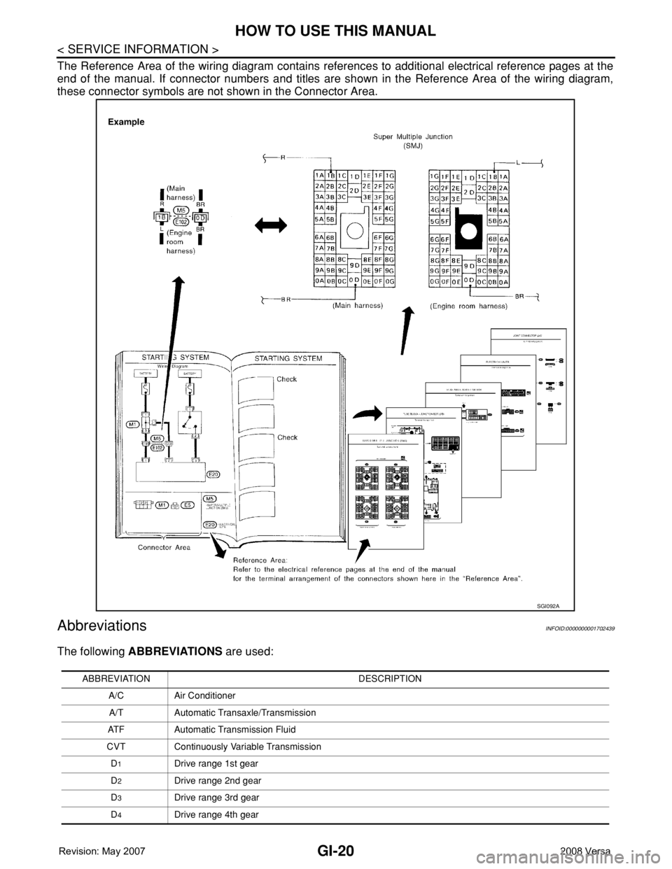
The Reference Area of the wiring diagram contains references to additional electrical reference pages at the
end of the manual. If connector numbers and titles are shown in the Reference Area of the wiring diagram,
these connector symbols are not shown in the Connector Area.
AbbreviationsINFOID:0000000001702439
The following ABBREVIATIONS are used:
SGI092A
ABBREVIATION DESCRIPTION
A/C Air Conditioner
A/T Automatic Transaxle/Transmission
ATF Automatic Transmission Fluid
CVT Continuously Variable Transmission
D
1Drive range 1st gear
D
2Drive range 2nd gear
D
3Drive range 3rd gear
D
4Drive range 4th gear
Page 1930 of 2771
POWER WINDOW SYSTEM
GW-29
< SERVICE INFORMATION >
C
D
E
F
G
H
J
K
L
MA
B
GW
N
O
P
WORK SUPPORT
DATA MONITOR
Power Window Auto Operation InitializationINFOID:0000000001871741
1. Turn the ignition switch ON.
2. Open the window—all the way DOWN.
3. Pull all the way UP on the switch and hold (close the window).
• Continue holding the switch all the way UP for 4 seconds after the window is closed.
4. Confirm the window is now operating correctly.
NOTE:
• If the window is still not operating correctly, refer to GW-29, "
Trouble Diagnosis Symptom Chart".
• The above initialization procedure must be performed if any of the following occur:
- Battery cable is disconnected
- Power window switch connector is disconnected
- Power window regulator is replaced
- Power window motor is replaced
- Window glass is removed
- Window glass run rubber is replaced
- Power window fuse is blown
- Window is partly opened and/or closed many times without being fully closed.
Trouble Diagnosis Symptom ChartINFOID:0000000001704148
Check that other systems using the signal of the following systems operate normally.
Work item Description
RETAINED PWRRAP signal’s power supply period can be changed by mode setting. Selects RAP signal’s power
supply period between three steps
• MODE1 (45 sec.)/MODE2 (OFF)/MODE3 (2 min.).
Work item Description
IGN ON SW Indicates (ON/OFF) condition of ignition switch
DOOR SW-DR Indicates (ON/OFF) condition of front door switch LH
DOOR SW-AS Indicates (ON/OFF) condition of front door switch RH
Symptom Repair order Refer to page
None of the power windows can be operated using any switch1. BCM power supply and ground circuit checkBCS-15
2. Main power window and door lock/unlock
power supply and ground circuit checkGW-30
3. Replace main power window and door lock/
unlock switchEI-32
Front power window LH alone does not operate1. Front power window motor LH circuit checkGW-312. Replace main power window and door lock/
unlock switchEI-32
Front power window RH does not operate from power window and
door lock/unlock switch RH only1. Front power window RH circuit check (power
window and door lock/unlock switch RH opera-
tion)GW-32
Front power window RH does not operate from main power window
and door lock/unlock switch only1. Replace main power window and door lock/
unlock switchEI-32
Front power window RH does not operate from any switch 1. Front power window motor RH circuit checkGW-32
Page 1931 of 2771
GW-30
< SERVICE INFORMATION >
POWER WINDOW SYSTEM
BCM Power Supply and Ground Circuit Inspection
INFOID:0000000001704149
Refer to BCS-15, "BCM Power Supply and Ground Circuit Inspection" .
Main Power Window and Door Lock/Unlock Switch Power Supply and Ground Circuit
Inspection
INFOID:0000000001704150
1.CHECK POWER SUPPLY CIRCUIT
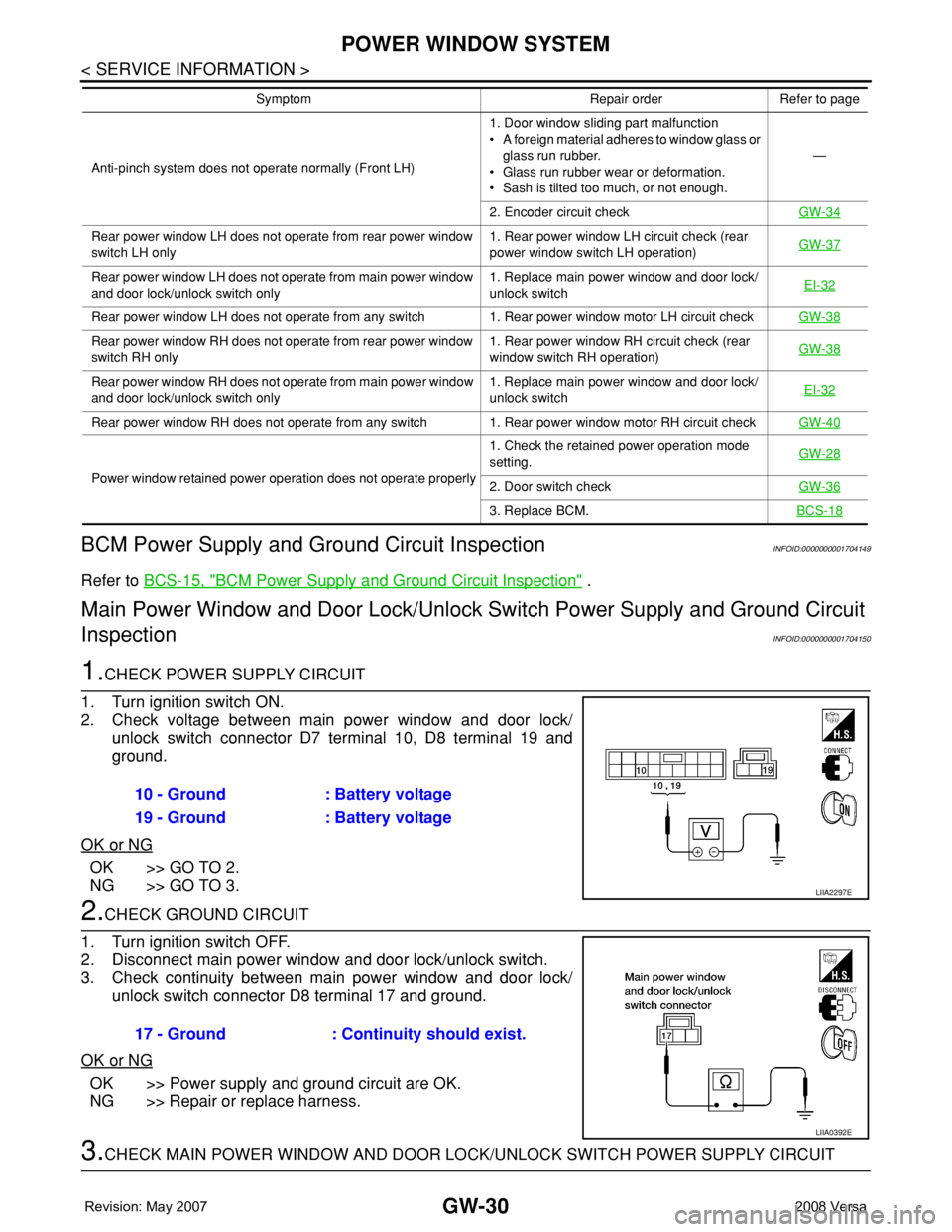
1. Turn ignition switch ON.
2. Check voltage between main power window and door lock/
unlock switch connector D7 terminal 10, D8 terminal 19 and
ground.
OK or NG
OK >> GO TO 2.
NG >> GO TO 3.
2.CHECK GROUND CIRCUIT
1. Turn ignition switch OFF.
2. Disconnect main power window and door lock/unlock switch.
3. Check continuity between main power window and door lock/
unlock switch connector D8 terminal 17 and ground.
OK or NG
OK >> Power supply and ground circuit are OK.
NG >> Repair or replace harness.
3.CHECK MAIN POWER WINDOW AND DOOR LOCK/UNLOCK SWITCH POWER SUPPLY CIRCUIT
Anti-pinch system does not operate normally (Front LH)1. Door window sliding part malfunction
• A foreign material adheres to window glass or
glass run rubber.
• Glass run rubber wear or deformation.
• Sash is tilted too much, or not enough.—
2. Encoder circuit checkGW-34
Rear power window LH does not operate from rear power window
switch LH only1. Rear power window LH circuit check (rear
power window switch LH operation)GW-37
Rear power window LH does not operate from main power window
and door lock/unlock switch only1. Replace main power window and door lock/
unlock switchEI-32
Rear power window LH does not operate from any switch 1. Rear power window motor LH circuit checkGW-38
Rear power window RH does not operate from rear power window
switch RH only1. Rear power window RH circuit check (rear
window switch RH operation)GW-38
Rear power window RH does not operate from main power window
and door lock/unlock switch only1. Replace main power window and door lock/
unlock switchEI-32
Rear power window RH does not operate from any switch 1. Rear power window motor RH circuit checkGW-40
Power window retained power operation does not operate properly1. Check the retained power operation mode
setting.GW-282. Door switch checkGW-36
3. Replace BCM.BCS-18
Symptom Repair order Refer to page
10 - Ground : Battery voltage
19 - Ground : Battery voltage
LIIA2297E
17 - Ground : Continuity should exist.
LIIA0392E
Page 1954 of 2771
REAR WINDOW DEFOGGER
GW-53
< SERVICE INFORMATION >
C
D
E
F
G
H
J
K
L
MA
B
GW
N
O
P
Work FlowINFOID:0000000001704172
1. Check the symptom and customer's requests.
2. Understand the outline of system. Refer to GW-49, "
System Description" .
3. According to the trouble diagnosis chart, repair or replace the cause of the malfunction. Refer to GW-53,
"Trouble Diagnosis Symptom Chart" .
4. Does rear window defogger operate normally? YES: GO TO 5, NO: GO TO 3.
5. Inspection End.
CONSULT-III Function (BCM)INFOID:0000000001704173
CONSULT-III can display each diagnostic item using the diagnostic test modes shown following.
DATA MONITOR
Display Item List
ACTIVE TEST
Display Item List
Trouble Diagnosis Symptom ChartINFOID:0000000001704174
Make sure other systems using the signal of the following systems operate normally.
BCM diagnostic
test itemDiagnostic mode Content
Inspection by partWORK SUPPORTSupports inspections and adjustments. Commands are transmitted to the BCM for
setting the status suitable for required operation, input/output signals are received
from the BCM and received data is displayed.
DATA MONITOR Displays BCM input/output data in real time.
ACTIVE TEST Operation of electrical loads can be checked by sending drive signal to them.
SELF-DIAG RESULTS Displays BCM self-diagnosis results.
CAN DIAG SUPPORT
MNTRThe results of transmit/receive diagnosis of CAN communication can be read.
ECU PART NUMBER BCM part number can be read.
CONFIGURATION Performs BCM configuration read/write functions.
Monitor item “Operation” Content
REAR DEF SW “ON/OFF” Indicates (ON/OFF) condition of the rear window defogger switch.
IGN ON SW “ON/OFF” Indicates (ON/OFF) condition of the ignition switch signal.
Test item Content
REAR WINDOW DEFOGGER Gives a drive signal to the rear window defogger to activate it.
Symptom Diagnoses / Service procedure Refer to page
Rear window defogger and door mirror defoggers do not
operate. (With heated mirrors)1. BCM power supply and ground circuit checkBCS-15
2. IPDM E/R auto active test checkPG-19
3. Rear window defogger switch circuit checkGW-54
4. Replace IPDM E/RPG-26
Page 1955 of 2771
GW-54
< SERVICE INFORMATION >
REAR WINDOW DEFOGGER
BCM Power Supply and Ground Circuit Inspection
INFOID:0000000001704175
Refer to BCS-15, "BCM Power Supply and Ground Circuit Inspection" .
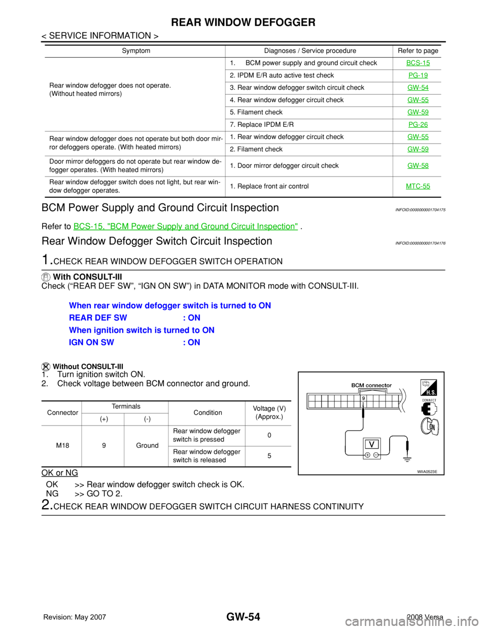
Rear Window Defogger Switch Circuit InspectionINFOID:0000000001704176
1.CHECK REAR WINDOW DEFOGGER SWITCH OPERATION
With CONSULT-III
Check (“REAR DEF SW”, “IGN ON SW”) in DATA MONITOR mode with CONSULT-III.
Without CONSULT-III
1. Turn ignition switch ON.
2. Check voltage between BCM connector and ground.
OK or NG
OK >> Rear window defogger switch check is OK.
NG >> GO TO 2.
2.CHECK REAR WINDOW DEFOGGER SWITCH CIRCUIT HARNESS CONTINUITY
Rear window defogger does not operate.
(Without heated mirrors)1. BCM power supply and ground circuit checkBCS-15
2. IPDM E/R auto active test checkPG-19
3. Rear window defogger switch circuit checkGW-54
4. Rear window defogger circuit checkGW-55
5. Filament checkGW-59
7. Replace IPDM E/RPG-26
Rear window defogger does not operate but both door mir-
ror defoggers operate. (With heated mirrors)1. Rear window defogger circuit checkGW-55
2. Filament checkGW-59
Door mirror defoggers do not operate but rear window de-
fogger operates. (With heated mirrors)1. Door mirror defogger circuit checkGW-58
Rear window defogger switch does not light, but rear win-
dow defogger operates.1. Replace front air controlMTC-55
Symptom Diagnoses / Service procedure Refer to page
When rear window defogger switch is turned to ON
REAR DEF SW : ON
When ignition switch is turned to ON
IGN ON SW : ON
ConnectorTe r m i n a l s
ConditionVoltage (V)
(Approx.)
(+) (-)
M18 9 GroundRear window defogger
switch is pressed0
Rear window defogger
switch is released5
WIIA0523E
Page 1977 of 2771
INSTRUMENT PANEL ASSEMBLY
IP-11
< ON-VEHICLE REPAIR >
C
D
E
F
G
H
J
K
L
MA
B
IP
N
O
P
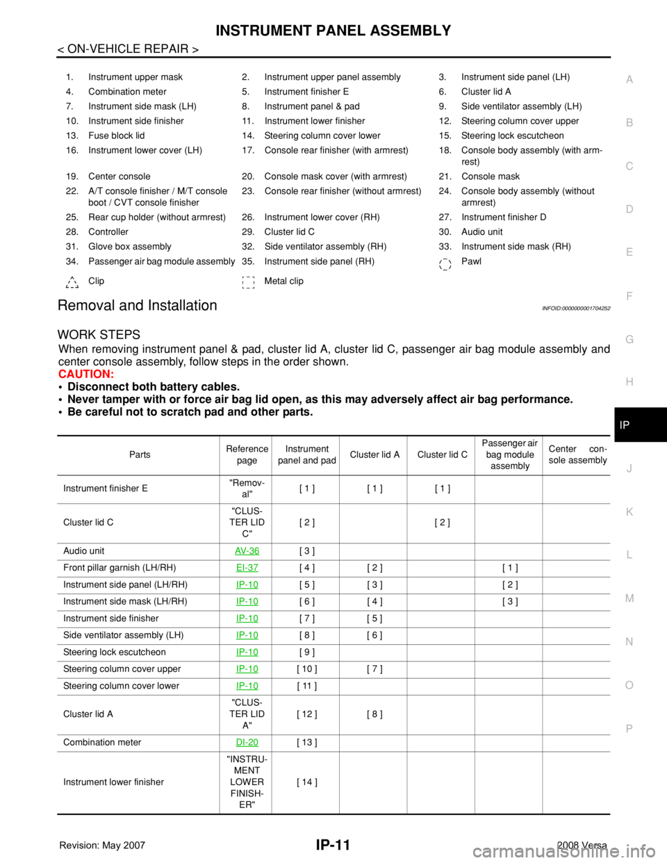
Removal and InstallationINFOID:0000000001704252
WORK STEPS
When removing instrument panel & pad, cluster lid A, cluster lid C, passenger air bag module assembly and
center console assembly, follow steps in the order shown.
CAUTION:
• Disconnect both battery cables.
• Never tamper with or force air bag lid open, as this may adversely affect air bag performance.
• Be careful not to scratch pad and other parts.
1. Instrument upper mask 2. Instrument upper panel assembly 3. Instrument side panel (LH)
4. Combination meter 5. Instrument finisher E 6. Cluster lid A
7. Instrument side mask (LH) 8. Instrument panel & pad 9. Side ventilator assembly (LH)
10. Instrument side finisher 11. Instrument lower finisher 12. Steering column cover upper
13. Fuse block lid 14. Steering column cover lower 15. Steering lock escutcheon
16. Instrument lower cover (LH) 17. Console rear finisher (with armrest) 18. Console body assembly (with arm-
rest)
19. Center console 20. Console mask cover (with armrest) 21. Console mask
22. A/T console finisher / M/T console
boot / CVT console finisher23. Console rear finisher (without armrest) 24. Console body assembly (without
armrest)
25. Rear cup holder (without armrest) 26. Instrument lower cover (RH) 27. Instrument finisher D
28. Controller 29. Cluster lid C 30. Audio unit
31. Glove box assembly 32. Side ventilator assembly (RH) 33. Instrument side mask (RH)
34. Passenger air bag module assembly 35. Instrument side panel (RH) Pawl
Clip Metal clip
PartsReference
pageInstrument
panel and padCluster lid A Cluster lid C Passenger air
bag module
assemblyCenter con-
sole assembly
Instrument finisher E"Remov-
al"[ 1 ] [ 1 ] [ 1 ]
Cluster lid C"CLUS-
TER LID
C"[ 2 ] [ 2 ]
Audio unitAV- 3 6
[ 3 ]
Front pillar garnish (LH/RH)EI-37
[ 4 ] [ 2 ] [ 1 ]
Instrument side panel (LH/RH)IP-10
[ 5 ] [ 3 ] [ 2 ]
Instrument side mask (LH/RH)IP-10
[ 6 ] [ 4 ] [ 3 ]
Instrument side finisherIP-10
[ 7 ] [ 5 ]
Side ventilator assembly (LH)IP-10
[ 8 ] [ 6 ]
Steering lock escutcheonIP-10
[ 9 ]
Steering column cover upperIP-10
[ 10 ] [ 7 ]
Steering column cover lowerIP-10
[ 11 ]
Cluster lid A"CLUS-
TER LID
A"[ 12 ] [ 8 ]
Combination meterDI-20
[ 13 ]
Instrument lower finisher"INSTRU-
MENT
LOWER
FINISH-
ER"[ 14 ]
Page 1978 of 2771
![NISSAN TIIDA 2008 Service Repair Manual IP-12
< ON-VEHICLE REPAIR >
INSTRUMENT PANEL ASSEMBLY
[ ]: Number indicates step in removal procedures.
INSTRUMENT PANEL ASSEMBLY
Removal
1. Pull instrument finisher E backward by approximately 30
deg NISSAN TIIDA 2008 Service Repair Manual IP-12
< ON-VEHICLE REPAIR >
INSTRUMENT PANEL ASSEMBLY
[ ]: Number indicates step in removal procedures.
INSTRUMENT PANEL ASSEMBLY
Removal
1. Pull instrument finisher E backward by approximately 30
deg](/manual-img/5/57399/w960_57399-1977.png)
IP-12
< ON-VEHICLE REPAIR >
INSTRUMENT PANEL ASSEMBLY
[ ]: Number indicates step in removal procedures.
INSTRUMENT PANEL ASSEMBLY
Removal
1. Pull instrument finisher E backward by approximately 30
degrees while disengaging the instrument finisher E metal clips
and pawl.
Glove box assembly"GLOVE
BOX AS-
SEMBLY"[ 15 ]
Side ventilator assembly (RH)IP-10
[ 16 ] [ 4 ]
Passenger air bag module assemblySRS-38
[ 17 ] [ 5 ]
Instrument upper maskIP-10
[ 18 ]
Instrument finisher DIP-10
[ 19 ]
Controller MTC-55
[ 20 ]
Instrument upper panel assembly IP-10
[ 21 ]
Console mask"Remov-
al"[ 22 ] [ 1 ]
CVT, A/T console finisherIP-23
[ 23 ] [ 2 ]
M/T console bootIP-23
[ 23 ] [ 2 ]
Console rear finisherIP-23
[ 24 ] [ 3 ]
Console mask cover (with arm rest)IP-23
[ 25 ] [ 4 ]
Rear cup holder (without arm rest)IP-23
[ 25 ] [ 4 ]
Console body assemblyIP-23
[ 26 ] [ 5 ]
Instrument lower cover (LH/RH)"INSTRU-
MENT
LOWER
FINISH-
ER"[ 27 ] [ 6 ]
Center console assembly"CEN-
TER
CON-
SOLE AS-
SEMBLY"[ 28 ] [ 7 ]
Fuse block lidIP-10
[ 29 ]
Lighting and turn signal switchLT- 6 0
[ 30 ]
Wiper & washer switchWW-22
[ 31 ]
Instrument panel & padIP-10
[ 32 ] PartsReference
pageInstrument
panel and padCluster lid A Cluster lid C Passenger air
bag module
assemblyCenter con-
sole assembly
WIIA1224E
Page 2264 of 2771
MA-4
< SERVICE INFORMATION >
GENERAL MAINTENANCE
GENERAL MAINTENANCE
Explanation of General MaintenanceINFOID:0000000001704720
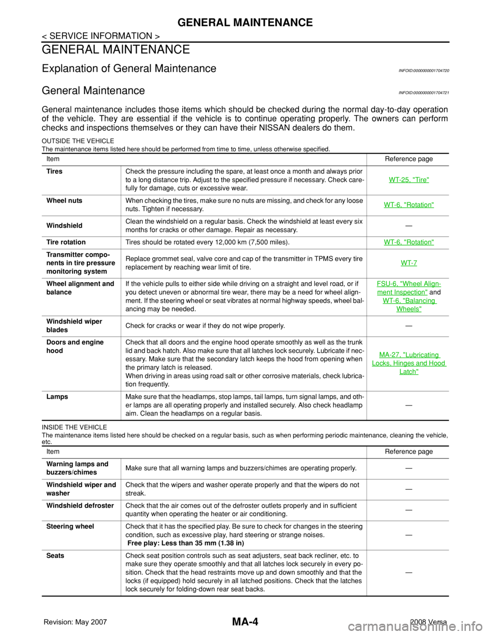
General MaintenanceINFOID:0000000001704721
General maintenance includes those items which should be checked during the normal day-to-day operation
of the vehicle. They are essential if the vehicle is to continue operating properly. The owners can perform
checks and inspections themselves or they can have their NISSAN dealers do them.
OUTSIDE THE VEHICLE
The maintenance items listed here should be performed from time to time, unless otherwise specified.
INSIDE THE VEHICLE
The maintenance items listed here should be checked on a regular basis, such as when performing periodic maintenance, cleaning the vehicle,
etc.
ItemReference page
TiresCheck the pressure including the spare, at least once a month and always prior
to a long distance trip. Adjust to the specified pressure if necessary. Check care-
fully for damage, cuts or excessive wear.WT-25, "
Tire"
Wheel nutsWhen checking the tires, make sure no nuts are missing, and check for any loose
nuts. Tighten if necessary.WT-6, "Rotation"
WindshieldClean the windshield on a regular basis. Check the windshield at least every six
months for cracks or other damage. Repair as necessary.—
Tire rotationTires should be rotated every 12,000 km (7,500 miles).WT-6, "
Rotation"
Transmitter compo-
nents in tire pressure
monitoring systemReplace grommet seal, valve core and cap of the transmitter in TPMS every tire
replacement by reaching wear limit of tire.WT-7
Wheel alignment and
balanceIf the vehicle pulls to either side while driving on a straight and level road, or if
you detect uneven or abnormal tire wear, there may be a need for wheel align-
ment. If the steering wheel or seat vibrates at normal highway speeds, wheel bal-
ancing may be needed.FSU-6, "Wheel Align-
ment Inspection" and
WT-6, "
Balancing
Wheels"
Windshield wiper
bladesCheck for cracks or wear if they do not wipe properly. —
Doors and engine
hoodCheck that all doors and the engine hood operate smoothly as well as the trunk
lid and back hatch. Also make sure that all latches lock securely. Lubricate if nec-
essary. Make sure that the secondary latch keeps the hood from opening when
the primary latch is released.
When driving in areas using road salt or other corrosive materials, check lubrica-
tion frequently.MA-27, "
Lubricating
Locks, Hinges and Hood
Latch"
LampsMake sure that the headlamps, stop lamps, tail lamps, turn signal lamps, and oth-
er lamps are all operating properly and installed securely. Also check headlamp
aim. Clean the headlamps on a regular basis.—
ItemReference page
Warning lamps and
buzzers/chimesMake sure that all warning lamps and buzzers/chimes are operating properly. —
Windshield wiper and
washerCheck that the wipers and washer operate properly and that the wipers do not
streak.—
Windshield defrosterCheck that the air comes out of the defroster outlets properly and in sufficient
quantity when operating the heater or air conditioning.—
Steering wheelCheck that it has the specified play. Be sure to check for changes in the steering
condition, such as excessive play, hard steering or strange noises.
Free play: Less than 35 mm (1.38 in)—
SeatsCheck seat position controls such as seat adjusters, seat back recliner, etc. to
make sure they operate smoothly and that all latches lock securely in every po-
sition. Check that the head restraints move up and down smoothly and that the
locks (if equipped) hold securely in all latched positions. Check that the latches
lock securely for folding-down rear seat backs.—