Page 2361 of 2771
TROUBLE DIAGNOSIS
MTC-23
< SERVICE INFORMATION >
C
D
E
F
G
H
I
K
L
MA
B
MTC
N
O
P
Component Parts and Harness Connector LocationINFOID:0000000001704296
ENGINE COMPARTMENT
PASSENGER COMPARTMENT
Magnet clutch does not engage in A/C, de-
frost/foot, or defrost mode.Go to Trouble Diagnosis Procedure for Magnet Clutch.MTC-37
Insufficient cooling Go to Trouble Diagnosis Procedure for Insufficient Cooling.MTC-45
Insufficient heating Go to Trouble Diagnosis Procedure for Insufficient Heating.MTC-52
Noise Go to Trouble Diagnosis Procedure for Noise.MTC-53
Symptom Reference Page
1. Refrigerant pressure sensor E17 2. A/C compressor F3
WJIA2235E
Page 2491 of 2771

PG-58
< SERVICE INFORMATION >
HARNESS
Wiring Diagram Codes (Cell Codes)
INFOID:0000000001704709
Use the chart below to find out what each wiring diagram code stands for.
Refer to the wiring diagram code in the alphabetical index to find the location (page number) of each wiring
diagram.
D3 D404 W/3 : Rear wiper motor
D4 D405 W/4 : Back door lock assembly
D4 D406 W/2 : Back door request switch
E2 D407 W/2 : High mounted stop lamp
D4 D408 BR/2 : Back door opener switch
E4 D409 B/1 : Condenser-1
C2 D410 — : Body ground
E3 D411 B/1 : Condenser-1
E1 D412 B/1 : Rear window defogger (+)
C2 D413 B/1 : Rear window defogger (-)
F3 D414 — : Body ground
Code Section Wiring Diagram Name
ABS BRC Anti-lock Brake System
A/C,M MTC Manual Air Conditioner
APPS1 EC Accelerator Pedal Position Sensor
A/F EC Air Fuel Ratio Sensor 1
A/FH EC Air Fuel Ratio Sensor 1 Heater
APPS2 EC Accelerator Pedal Position Sensor
APPS3 EC Accelerator Pedal Position Sensor
ASC/BS EC ASCD Brake Switch
ASC/SW EC ASCD Steering Switch
ASCBOF EC ASCD Brake Switch
ASCIND EC ASCD Indicator
AT/IND DI A/T Indicator Lamp
AUDIO AV Audio
BACK/L LT Back-up Lamp
BA/FTS AT A/T Fluid Temperature Sensor and TCM Power Supply
B/DOOR BL Back Door Opener
BRK/SW EC Brake Switch
CAN AT CAN Communication Line
CAN CVT CAN Communication Line
CAN EC CAN Communication Line
CAN LAN CAN System
CHARGE SC Charging System
CHIME DI Warning Chime
COOL/F EC Cooling Fan Control
COMBSW LT Combination Switch
CVTIND DI CVT Indicator Lamp
D/LOCK BL Power Door Lock
DEF GW Rear Window Defogger
DTRL LT Headlamp - With Daytime Light System
ECTS EC Engine Coolant Temperature Sensor
ENGSS AT Engine Speed Signal
EPS STC Electronic Controlled Power Steering
ETC1 EC Electric Throttle Control Function
Page 2498 of 2771
HARNESS CONNECTOR
PG-65
< SERVICE INFORMATION >
C
D
E
F
G
H
I
J
L
MA
B
PG
N
O
P
HARNESS CONNECTOR
DescriptionINFOID:0000000001704711
HARNESS CONNECTOR (TAB-LOCKING TYPE)
• The tab-locking type connectors help prevent accidental looseness or disconnection.
• The tab-locking type connectors are disconnected by pushing or lifting the locking tab(s). Refer to the illus-
tration below.
Refer to the next page for description of the slide-locking type connector.
CAUTION:
Do not pull the harness or wires when disconnecting the connector.
[Example]
HARNESS CONNECTOR (SLIDE-LOCKING TYPE)
• A new style slide-locking type connector is used on certain systems and components, especially those
related to OBD.
• The slide-locking type connectors help prevent incomplete locking and accidental looseness or disconnec-
tion.
• The slide-locking type connectors are disconnected by pushing or pulling the slider. Refer to the figure
below.
SEL769DA
Page 2511 of 2771

NOISE, VIBRATION AND HARSHNESS (NVH) TROUBLESHOOTING
PS-5
< SERVICE INFORMATION >
C
D
E
F
H
I
J
K
L
MA
B
PS
N
O
P
NOISE, VIBRATION AND HARSHNESS (NVH) TROUBLESHOOTING
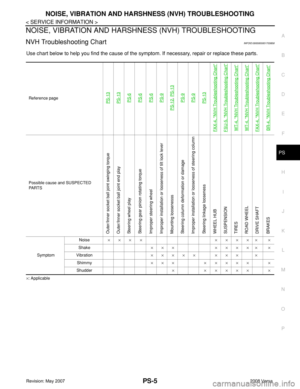
NVH Troubleshooting ChartINFOID:0000000001703858
Use chart below to help you find the cause of the symptom. If necessary, repair or replace these parts.
×: ApplicableReference page
PS-13PS-13PS-6PS-6PS-6PS-9
PS-12
, PS-13PS-9PS-9PS-13
FAX-4, "
NVH Troubleshooting Chart
"
FSU-5, "
NVH Troubleshooting Chart
"
WT-4, "
NVH Troubleshooting Chart
"
WT-4, "
NVH Troubleshooting Chart
"
FAX-4, "
NVH Troubleshooting Chart
"
BR-4, "
NVH Troubleshooting Chart
"
Possible cause and SUSPECTED
PA R T S
Outer/Inner socket ball joint swinging torque
Outer/Inner socket ball joint end play
Steering wheel play
Steering gear pinion rotating torque
Improper steering wheel
Improper installation or looseness of tilt lock lever
Mounting loosenesss
Steering column deformation or damage
Improper installation or looseness of steering column
Steering linkage looseness
WHEEL HUB
SUSPENSION
TIRES
ROAD WHEEL
DRIVE SHAFT
BRAKES
SymptomNoise××× × ××××× ×
Shake××× ××××× ×
Vibration××××× ××× ×
Shimmy××× × ×××× ×
Shudder× × ×××× ×
Page 2527 of 2771
NOISE, VIBRATION AND HARSHNESS (NVH) TROUBLESHOOTING
RAX-3
< SERVICE INFORMATION >
C
E
F
G
H
I
J
K
L
MA
B
RAX
N
O
P
NOISE, VIBRATION AND HARSHNESS (NVH) TROUBLESHOOTING
NVH Troubleshooting ChartINFOID:0000000001703711
Use chart below to help you find the cause of the symptom. If necessary, repair or replace these parts.
×: ApplicableReference page
RAX-4—
RAX-4
RSU-4, "
NVH Troubleshooting Chart
"
WT-4, "
NVH Troubleshooting Chart
"
WT-4, "
NVH Troubleshooting Chart
"
BR-4, "
NVH Troubleshooting Chart
"
PS-5, "
NVH Troubleshooting Chart
"
Possible cause and SUSPECTED PARTS
Improper installation, looseness
Parts interference
Wheel bearing damage
REAR SUSPENSION
TIRES
ROAD WHEEL
BRAKES
STEERING
Symptom REAR AXLENoise×× ×××××
Shake×× ×××××
Vibration×× ×× ×
Shimmy×× ×××××
Shudder× ×××××
Poor quality ride or handling××××××
Page 2546 of 2771

RF-16
< FUNCTION DIAGNOSIS >
TROUBLE DIAGNOSIS
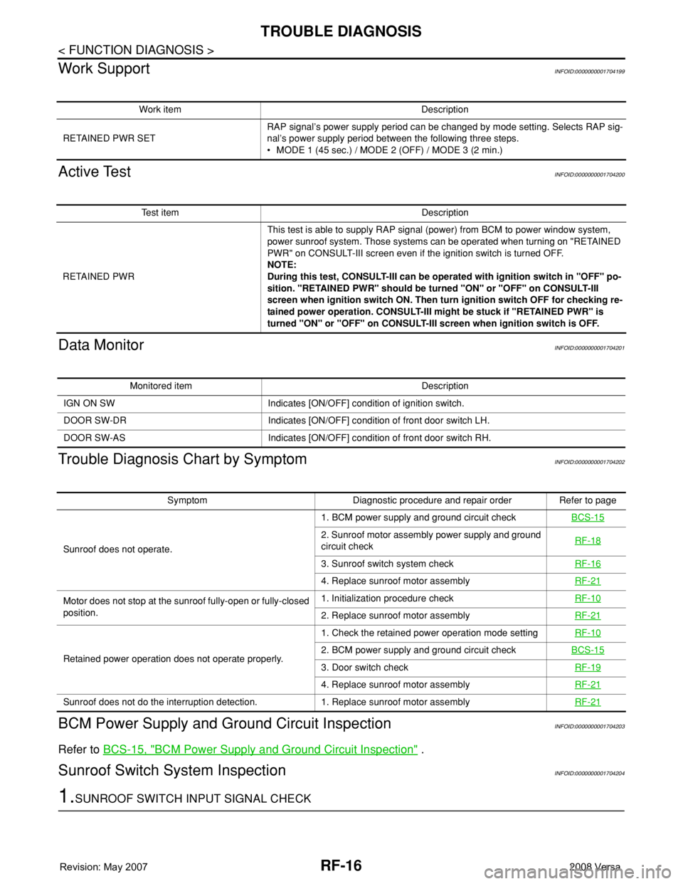
Work Support
INFOID:0000000001704199
Active TestINFOID:0000000001704200
Data MonitorINFOID:0000000001704201
Trouble Diagnosis Chart by SymptomINFOID:0000000001704202
BCM Power Supply and Ground Circuit InspectionINFOID:0000000001704203
Refer to BCS-15, "BCM Power Supply and Ground Circuit Inspection" .
Sunroof Switch System InspectionINFOID:0000000001704204
1.SUNROOF SWITCH INPUT SIGNAL CHECK
Work item Description
RETAINED PWR SETRAP signal’s power supply period can be changed by mode setting. Selects RAP sig-
nal’s power supply period between the following three steps.
• MODE 1 (45 sec.) / MODE 2 (OFF) / MODE 3 (2 min.)
Test item Description
RETAINED PWRThis test is able to supply RAP signal (power) from BCM to power window system,
power sunroof system. Those systems can be operated when turning on "RETAINED
PWR" on CONSULT-III screen even if the ignition switch is turned OFF.
NOTE:
During this test, CONSULT-III can be operated with ignition switch in "OFF" po-
sition. "RETAINED PWR" should be turned "ON" or "OFF" on CONSULT-III
screen when ignition switch ON. Then turn ignition switch OFF for checking re-
tained power operation. CONSULT-III might be stuck if "RETAINED PWR" is
turned "ON" or "OFF" on CONSULT-III screen when ignition switch is OFF.
Monitored item Description
IGN ON SW Indicates [ON/OFF] condition of ignition switch.
DOOR SW-DR Indicates [ON/OFF] condition of front door switch LH.
DOOR SW-AS Indicates [ON/OFF] condition of front door switch RH.
Symptom Diagnostic procedure and repair order Refer to page
Sunroof does not operate.1. BCM power supply and ground circuit checkBCS-15
2. Sunroof motor assembly power supply and ground
circuit checkRF-18
3. Sunroof switch system checkRF-16
4. Replace sunroof motor assemblyRF-21
Motor does not stop at the sunroof fully-open or fully-closed
position.1. Initialization procedure checkRF-10
2. Replace sunroof motor assemblyRF-21
Retained power operation does not operate properly.1. Check the retained power operation mode settingRF-102. BCM power supply and ground circuit checkBCS-15
3. Door switch checkRF-19
4. Replace sunroof motor assemblyRF-21
Sunroof does not do the interruption detection. 1. Replace sunroof motor assemblyRF-21
Page 2563 of 2771
RSU-4
< SERVICE INFORMATION >
NOISE, VIBRATION AND HARSHNESS (NVH) TROUBLESHOOTING
NOISE, VIBRATION AND HARSHNESS (NVH) TROUBLESHOOTING
NVH Troubleshooting ChartINFOID:0000000001703735
Use chart below to help you find the cause of the symptom. If necessary, repair or replace these parts.
×: ApplicableReference page
RSU-7RSU-8RSU-8RSU-8RSU-10RSU-7RSU-5RSU-4WT-4WT-4BR-4PS-5
Possible cause and SUSPECTED PARTS
Improper installation, looseness
Shock absorber deformation, damage or deflection
Bushing or mounting deterioration
Parts interference
Spring fatigue
Suspension looseness
Incorrect wheel alignment
REAR AXLE
TIRES
ROAD WHEEL
BRAKES
STEERING
SymptomNoise×××××× ×××××
Shake×××× × ×××××
Vibration××××× ×× ×
Shimmy×××× ××××××
Judder ××× ×××××
Poor quality ride or handling××××× ××××
Page 2694 of 2771
![NISSAN TIIDA 2008 Service Repair Manual TROUBLE DIAGNOSIS
STC-11
< SERVICE INFORMATION >[EPS]
C
D
E
F
H
I
J
K
L
MA
B
STC
N
O
P
Data are reference values and are measured between each terminal and ground.
CAUTION:
When using a circuit tester NISSAN TIIDA 2008 Service Repair Manual TROUBLE DIAGNOSIS
STC-11
< SERVICE INFORMATION >[EPS]
C
D
E
F
H
I
J
K
L
MA
B
STC
N
O
P
Data are reference values and are measured between each terminal and ground.
CAUTION:
When using a circuit tester](/manual-img/5/57399/w960_57399-2693.png)
TROUBLE DIAGNOSIS
STC-11
< SERVICE INFORMATION >[EPS]
C
D
E
F
H
I
J
K
L
MA
B
STC
N
O
P
Data are reference values and are measured between each terminal and ground.
CAUTION:
When using a circuit tester to measure voltage for inspection, be sure not to extend forcibly any connector terminals.
CONSULT-III Function (EPS)INFOID:0000000001703881
FUNCTION
CONSULT-III can display each diagnostic item using the diagnostic test modes shown following.
SELF-DIAG RESULTS MODE
Display Item List
Te r m i n a lWire
colorItem Condition Data (Approx.)
4 V Torque sensor sub Engine runningSteering wheel: Not steering
(There in no steering force)2.5 V
Steering wheel: Steering1.7 V – 3.3 V
(The value is changed accord-
ing to steering left or right)
5 BR Torque sensor power supplyIgnition switch: ON 8 V
Ignition switch: OFF 0 V
6 G Torque sensor main Engine runningSteering wheel: Not steering
(There is no steering force)2.5 V
Steering wheel: Steering1.7 V – 3.3 V
(The value is changed accord-
ing to steering left or right)
7 R Torque sensor ground Always 0 V
9 L CAN-H — —
10 O Power supplyIgnition switch: ON Battery voltage
Ignition switch: OFF 0 V
16 P CAN-L — —
17 R Power supply (Memory back-up)Ignition switch: ON Battery voltage
Ignition switch: OFF Battery voltage
18 B Ground Always 0 V
19 — Motor (+) — —
20 — Motor (–) — —
Diagnostic test mode Function Reference page
Self-diagnostic results • Self-diagnostic results can be read and erased quickly."SELF-DIAG
RESULTS
MODE"
Data monitor • Input/Output data in the EPS control unit can be read."DATA MONI-
TOR"
CAN diagnostic support monitor • The results of transmit/receive diagnosis of CAN communication can be read.LAN-6
ECU part number • EPS control unit part number can be read."EPS CON-
TROL UNIT
PART NUM-
BER"