2008 NISSAN TIIDA engine control
[x] Cancel search: engine controlPage 156 of 2771
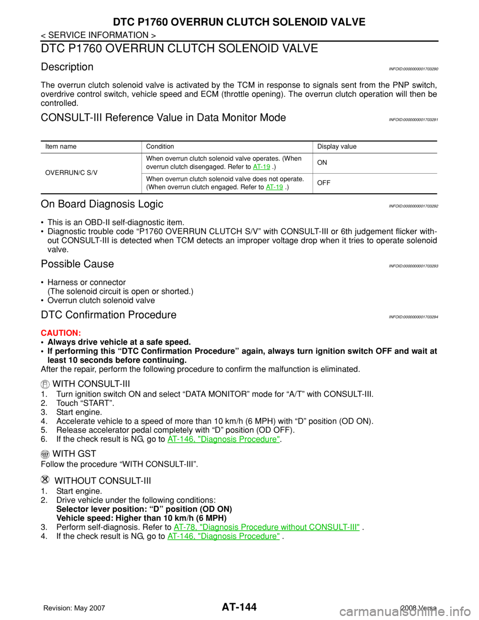
AT-144
< SERVICE INFORMATION >
DTC P1760 OVERRUN CLUTCH SOLENOID VALVE
DTC P1760 OVERRUN CLUTCH SOLENOID VALVE
DescriptionINFOID:0000000001703290
The overrun clutch solenoid valve is activated by the TCM in response to signals sent from the PNP switch,
overdrive control switch, vehicle speed and ECM (throttle opening). The overrun clutch operation will then be
controlled.
CONSULT-III Reference Value in Data Monitor ModeINFOID:0000000001703291
On Board Diagnosis LogicINFOID:0000000001703292
• This is an OBD-II self-diagnostic item.
• Diagnostic trouble code “P1760 OVERRUN CLUTCH S/V” with CONSULT-III or 6th judgement flicker with-
out CONSULT-III is detected when TCM detects an improper voltage drop when it tries to operate solenoid
valve.
Possible CauseINFOID:0000000001703293
• Harness or connector
(The solenoid circuit is open or shorted.)
• Overrun clutch solenoid valve
DTC Confirmation ProcedureINFOID:0000000001703294
CAUTION:
• Always drive vehicle at a safe speed.
• If performing this “DTC Confirmation Procedure” again, always turn ignition switch OFF and wait at
least 10 seconds before continuing.
After the repair, perform the following procedure to confirm the malfunction is eliminated.
WITH CONSULT-III
1. Turn ignition switch ON and select “DATA MONITOR” mode for “A/T” with CONSULT-III.
2. Touch “START”.
3. Start engine.
4. Accelerate vehicle to a speed of more than 10 km/h (6 MPH) with “D” position (OD ON).
5. Release accelerator pedal completely with “D” position (OD OFF).
6. If the check result is NG, go to AT-146, "
Diagnosis Procedure".
WITH GST
Follow the procedure “WITH CONSULT-III”.
WITHOUT CONSULT-III
1. Start engine.
2. Drive vehicle under the following conditions:
Selector lever position: “D” position (OD ON)
Vehicle speed: Higher than 10 km/h (6 MPH)
3. Perform self-diagnosis. Refer to AT-78, "
Diagnosis Procedure without CONSULT-III" .
4. If the check result is NG, go to AT-146, "
Diagnosis Procedure" .
Item name Condition Display value
OVERRUN/C S/VWhen overrun clutch solenoid valve operates. (When
overrun clutch disengaged. Refer to AT- 1 9
.)ON
When overrun clutch solenoid valve does not operate.
(When overrun clutch engaged. Refer to AT- 1 9
.)OFF
Page 159 of 2771
DTC P1760 OVERRUN CLUTCH SOLENOID VALVE
AT-147
< SERVICE INFORMATION >
D
E
F
G
H
I
J
K
L
MA
B
AT
N
O
P
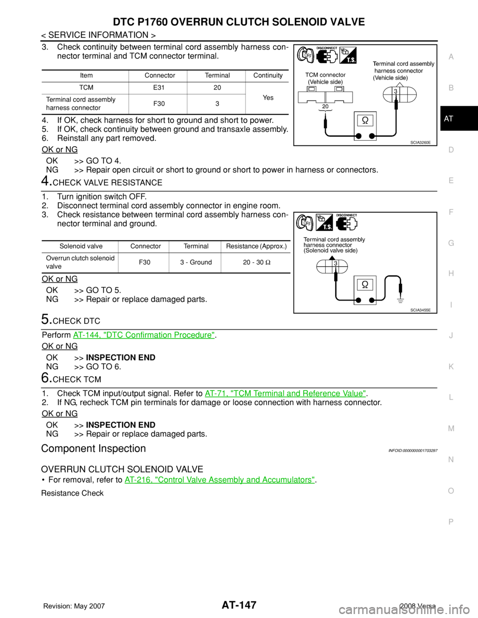
3. Check continuity between terminal cord assembly harness con-
nector terminal and TCM connector terminal.
4. If OK, check harness for short to ground and short to power.
5. If OK, check continuity between ground and transaxle assembly.
6. Reinstall any part removed.
OK or NG
OK >> GO TO 4.
NG >> Repair open circuit or short to ground or short to power in harness or connectors.
4.CHECK VALVE RESISTANCE
1. Turn ignition switch OFF.
2. Disconnect terminal cord assembly connector in engine room.
3. Check resistance between terminal cord assembly harness con-
nector terminal and ground.
OK or NG
OK >> GO TO 5.
NG >> Repair or replace damaged parts.
5.CHECK DTC
Perform AT-144, "
DTC Confirmation Procedure".
OK or NG
OK >>INSPECTION END
NG >> GO TO 6.
6.CHECK TCM
1. Check TCM input/output signal. Refer to AT-71, "
TCM Terminal and Reference Value".
2. If NG, recheck TCM pin terminals for damage or loose connection with harness connector.
OK or NG
OK >>INSPECTION END
NG >> Repair or replace damaged parts.
Component InspectionINFOID:0000000001703297
OVERRUN CLUTCH SOLENOID VALVE
• For removal, refer to AT-216, "Control Valve Assembly and Accumulators".
Resistance Check
Item Connector Terminal Continuity
TCM E31 20
Ye s
Terminal cord assembly
harness connectorF30 3
SCIA3260E
Solenoid valve Connector Terminal Resistance (Approx.)
Overrun clutch solenoid
valveF30 3 - Ground 20 - 30 Ω
SCIA3455E
Page 168 of 2771
AT-156
< SERVICE INFORMATION >
DTC BATT/FLUID TEMP SEN (A/T FLUID TEMP SENSOR CIRCUIT AND TCM
POWER SOURCE)
OK >> GO TO 7.
NG >> Repair open circuit or short to ground or short to power in harness or connectors.
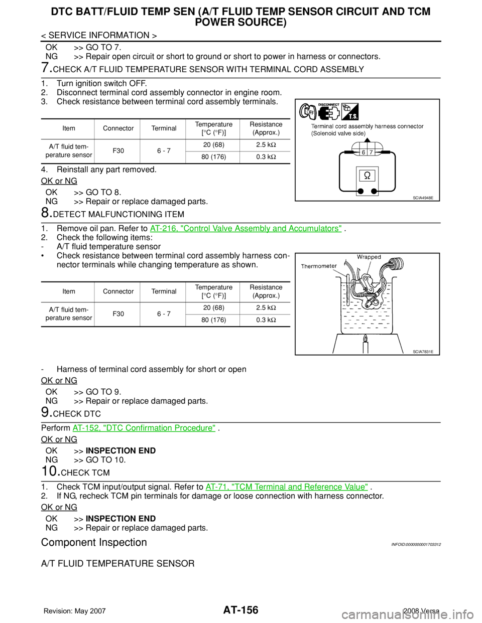
7.CHECK A/T FLUID TEMPERATURE SENSOR WITH TERMINAL CORD ASSEMBLY
1. Turn ignition switch OFF.
2. Disconnect terminal cord assembly connector in engine room.
3. Check resistance between terminal cord assembly terminals.
4. Reinstall any part removed.
OK or NG
OK >> GO TO 8.
NG >> Repair or replace damaged parts.
8.DETECT MALFUNCTIONING ITEM
1. Remove oil pan. Refer to AT-216, "
Control Valve Assembly and Accumulators" .
2. Check the following items:
- A/T fluid temperature sensor
• Check resistance between terminal cord assembly harness con-
nector terminals while changing temperature as shown.
- Harness of terminal cord assembly for short or open
OK or NG
OK >> GO TO 9.
NG >> Repair or replace damaged parts.
9.CHECK DTC
Perform AT-152, "
DTC Confirmation Procedure" .
OK or NG
OK >>INSPECTION END
NG >> GO TO 10.
10.CHECK TCM
1. Check TCM input/output signal. Refer to AT-71, "
TCM Terminal and Reference Value" .
2. If NG, recheck TCM pin terminals for damage or loose connection with harness connector.
OK or NG
OK >>INSPECTION END
NG >> Repair or replace damaged parts.
Component InspectionINFOID:0000000001703312
A/T FLUID TEMPERATURE SENSOR
Item Connector Terminal Temperature
[°C (°F)]Resistance
(Approx.)
A/T fluid tem-
perature sensorF30 6 - 720 (68) 2.5 kΩ
80 (176) 0.3 kΩ
SCIA4948E
Item Connector Terminal Temperature
[°C (°F)]Resistance
(Approx.)
A/T fluid tem-
perature sensorF30 6 - 720 (68) 2.5 kΩ
80 (176) 0.3 kΩ
SCIA7831E
Page 175 of 2771
CONTROL UNIT (RAM), CONTROL UNIT (ROM)
AT-163
< SERVICE INFORMATION >
D
E
F
G
H
I
J
K
L
MA
B
AT
N
O
P
CONTROL UNIT (RAM), CONTROL UNIT (ROM)
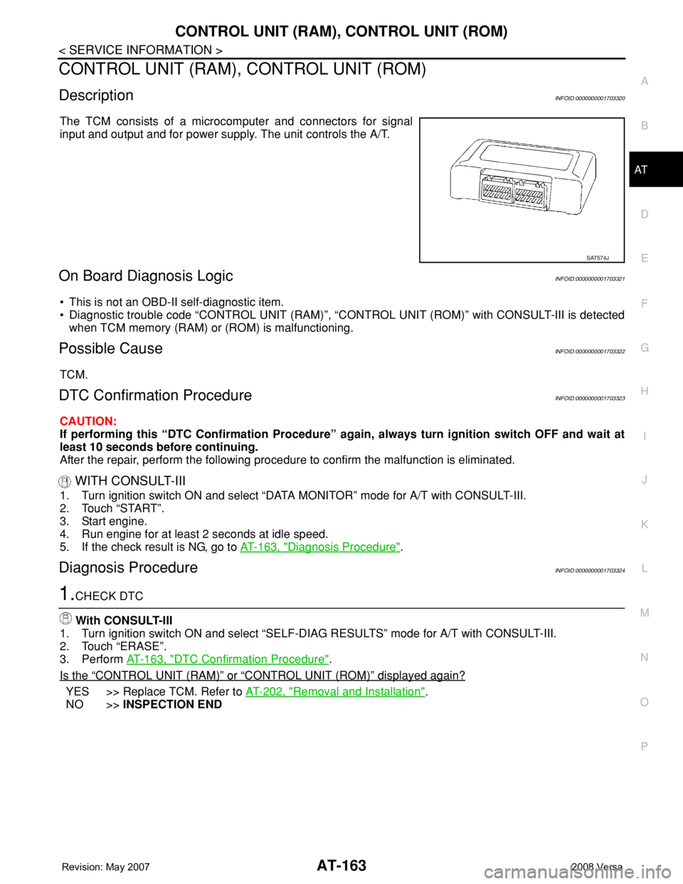
DescriptionINFOID:0000000001703320
The TCM consists of a microcomputer and connectors for signal
input and output and for power supply. The unit controls the A/T.
On Board Diagnosis LogicINFOID:0000000001703321
• This is not an OBD-II self-diagnostic item.
• Diagnostic trouble code “CONTROL UNIT (RAM)”, “CONTROL UNIT (ROM)” with CONSULT-III is detected
when TCM memory (RAM) or (ROM) is malfunctioning.
Possible CauseINFOID:0000000001703322
TCM.
DTC Confirmation ProcedureINFOID:0000000001703323
CAUTION:
If performing this “DTC Confirmation Procedure” again, always turn ignition switch OFF and wait at
least 10 seconds before continuing.
After the repair, perform the following procedure to confirm the malfunction is eliminated.
WITH CONSULT-III
1. Turn ignition switch ON and select “DATA MONITOR” mode for A/T with CONSULT-III.
2. Touch “START”.
3. Start engine.
4. Run engine for at least 2 seconds at idle speed.
5. If the check result is NG, go to AT-163, "
Diagnosis Procedure".
Diagnosis ProcedureINFOID:0000000001703324
1.CHECK DTC
With CONSULT-III
1. Turn ignition switch ON and select “SELF-DIAG RESULTS” mode for A/T with CONSULT-III.
2. Touch “ERASE”.
3. Perform AT-163, "
DTC Confirmation Procedure".
Is the
“CONTROL UNIT (RAM)” or “CONTROL UNIT (ROM)” displayed again?
YES >> Replace TCM. Refer to AT-202, "Removal and Installation".
NO >>INSPECTION END
SAT574J
Page 181 of 2771
PNP, OD SWITCH AND CLOSED THROTTLE, WIDE OPEN THROTTLE POSI-
TION SIGNAL CIRCUIT
AT-169
< SERVICE INFORMATION >
D
E
F
G
H
I
J
K
L
MA
B
AT
N
O
P
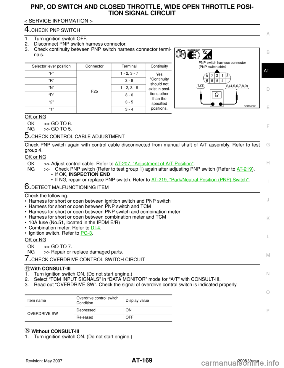
4.CHECK PNP SWITCH
1. Turn ignition switch OFF.
2. Disconnect PNP switch harness connector.
3. Check continuity between PNP switch harness connector termi-
nals.
OK or NG
OK >> GO TO 6.
NG >> GO TO 5.
5.CHECK CONTROL CABLE ADJUSTMENT
Check PNP switch again with control cable disconnected from manual shaft of A/T assembly. Refer to test
group 4.
OK or NG
OK >> Adjust control cable. Refer to AT-207, "Adjustment of A/T Position".
NG >> Check PNP switch (Refer to test group 1) again after adjusting PNP switch (Refer to AT-219
).
• If OK, INSPECTION END
• If NG, repair or replace PNP switch. Refer to AT-219, "
Park/Neutral Position (PNP) Switch".
6.DETECT MALFUNCTIONING ITEM
Check the following.
• Harness for short or open between ignition switch and PNP switch
• Harness for short or open between PNP switch and TCM
• Harness for short or open between PNP switch and combination meter
• Harness for short or open between combination meter and TCM
• 10A fuse (No.51, located in the IPDM E/R)
• Combination meter. Refer to DI-4
.
• Ignition switch. Refer to PG-3
.
OK or NG
OK >> GO TO 7.
NG >> Repair or replace damaged parts.
7.CHECK OVERDRIVE CONTROL SWITCH CIRCUIT
With CONSULT-III
1. Turn ignition switch ON. (Do not start engine.)
2. Select “TCM INPUT SIGNALS” in “DATA MONITOR” mode for “A/T” with CONSULT-III.
3. Read out “OVERDRIVE SW”. Check the signal of overdrive control switch is indicated properly.
Without CONSULT-III
1. Turn ignition switch ON. (Do not start engine.)
Selector lever position Connector Terminal Continuity
“P”
F251 - 2, 3 - 7
Ye s
*Continuity
should not
exist in posi-
tions other
than the
specified
positions. “R” 3 - 8
“N” 1 - 2, 3 - 9
“D” 3 - 6
“2” 3 - 5
“1” 3 - 4
SCIA5588E
Item nameOverdrive control switch
ConditionDisplay value
OVERDRIVE SWDepressed ON
Released OFF
Page 182 of 2771
AT-170
< SERVICE INFORMATION >
PNP, OD SWITCH AND CLOSED THROTTLE, WIDE OPEN THROTTLE POSI-
TION SIGNAL CIRCUIT
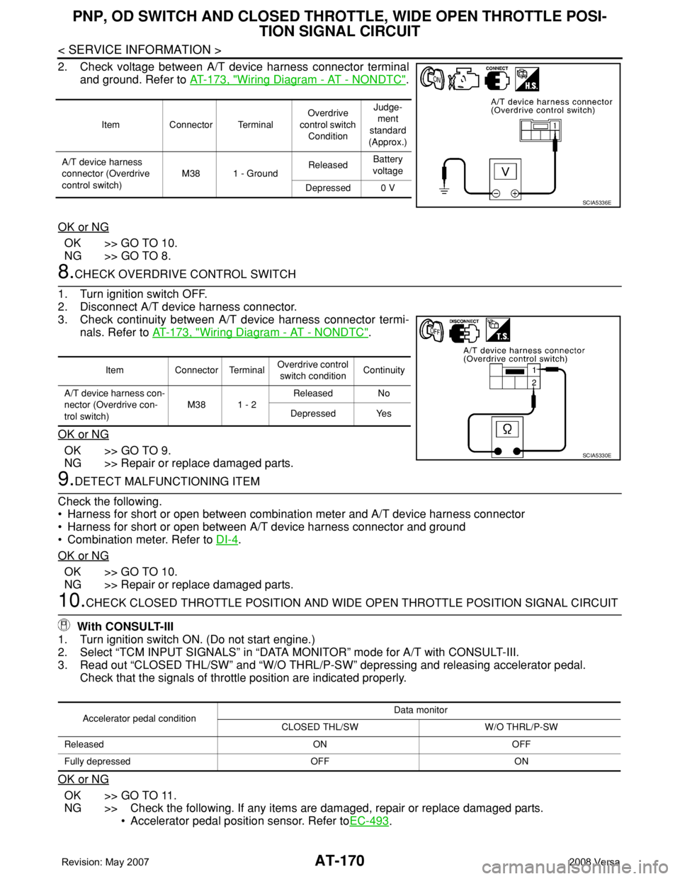
2. Check voltage between A/T device harness connector terminal
and ground. Refer to AT-173, "
Wiring Diagram - AT - NONDTC".
OK or NG
OK >> GO TO 10.
NG >> GO TO 8.
8.CHECK OVERDRIVE CONTROL SWITCH
1. Turn ignition switch OFF.
2. Disconnect A/T device harness connector.
3. Check continuity between A/T device harness connector termi-
nals. Refer to AT-173, "
Wiring Diagram - AT - NONDTC".
OK or NG
OK >> GO TO 9.
NG >> Repair or replace damaged parts.
9.DETECT MALFUNCTIONING ITEM
Check the following.
• Harness for short or open between combination meter and A/T device harness connector
• Harness for short or open between A/T device harness connector and ground
• Combination meter. Refer to DI-4
.
OK or NG
OK >> GO TO 10.
NG >> Repair or replace damaged parts.
10.CHECK CLOSED THROTTLE POSITION AND WIDE OPEN THROTTLE POSITION SIGNAL CIRCUIT
With CONSULT-III
1. Turn ignition switch ON. (Do not start engine.)
2. Select “TCM INPUT SIGNALS” in “DATA MONITOR” mode for A/T with CONSULT-III.
3. Read out “CLOSED THL/SW” and “W/O THRL/P-SW” depressing and releasing accelerator pedal.
Check that the signals of throttle position are indicated properly.
OK or NG
OK >> GO TO 11.
NG >> Check the following. If any items are damaged, repair or replace damaged parts.
• Accelerator pedal position sensor. Refer toEC-493
.
Item Connector TerminalOverdrive
control switch
ConditionJudge-
ment
standard
(Approx.)
A/T device harness
connector (Overdrive
control switch)M38 1 - GroundReleasedBattery
voltage
Depressed 0 V
SCIA5336E
Item Connector TerminalOverdrive control
switch conditionContinuity
A/T device harness con-
nector (Overdrive con-
trol switch)M38 1 - 2Released No
Depressed Yes
SCIA5330E
Accelerator pedal conditionData monitor
CLOSED THL/SW W/O THRL/P-SW
Released ON OFF
Fully depressed OFF ON
Page 190 of 2771
AT-178
< SERVICE INFORMATION >
TROUBLE DIAGNOSIS FOR SYMPTOMS
3. Check continuity between TCM connector terminals and ground.
Refer to AT-164, "
Wiring Diagram - AT - MAIN" .
OK or NG
OK >> GO TO 5.
NG >> Repair open circuit or short to ground or short to power
in harness or connectors.
5.DETECT MALFUNCTIONING ITEM
Check the following.
• Harness for short or open between ignition switch and combination meter
• Combination meter. Refer to DI-4
.
OK or NG
OK >> GO TO 6.
NG >> Repair or replace damaged parts.
6.CHECK SYMPTOM
Check again. Refer to AT-53, "
Check Before Engine Is Started" .
OK or NG
OK >>INSPECTION END
NG >> GO TO 7.
7.CHECK TCM
1. Check TCM input/output. Refer to AT-71, "
TCM Terminal and Reference Value" .
2. If NG, recheck TCM pin terminals for damage or loose connection with harness connector.
OK or NG
OK >>INSPECTION END
NG >> Repair or replace damaged parts.
Engine Cannot Be Started in "P" and "N" PositionINFOID:0000000001703336
SYMPTOM:
•Engine cannot be started with selector lever in “P” or “N” position.
•Engine can be started with selector lever in “D”, “2”, “1” or “R” position.
DIAGNOSTIC PROCEDURE
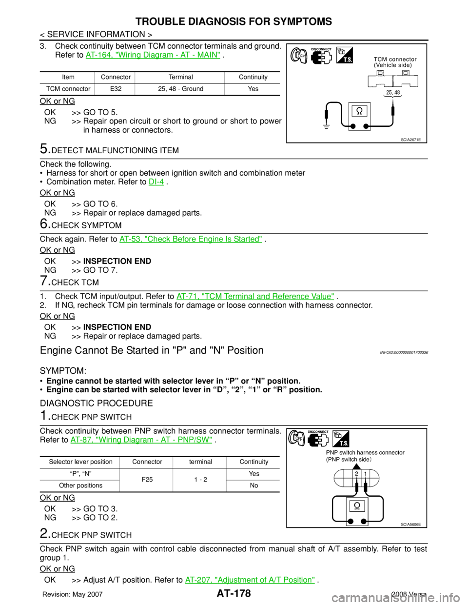
1.CHECK PNP SWITCH
Check continuity between PNP switch harness connector terminals.
Refer to AT-87, "
Wiring Diagram - AT - PNP/SW" .
OK or NG
OK >> GO TO 3.
NG >> GO TO 2.
2.CHECK PNP SWITCH
Check PNP switch again with control cable disconnected from manual shaft of A/T assembly. Refer to test
group 1.
OK or NG
OK >> Adjust A/T position. Refer to AT-207, "Adjustment of A/T Position" .
Item Connector Terminal Continuity
TCM connector E32 25, 48 - Ground Yes
SCIA2671E
Selector lever position Connector terminal Continuity
“P”, “N”
F25 1 - 2Ye s
Other positions No
SCIA5606E
Page 204 of 2771

AT-192
< SERVICE INFORMATION >
TROUBLE DIAGNOSIS FOR SYMPTOMS
OK >>INSPECTION END
NG >> GO TO 3.
3.CHECK TCM
1. Check TCM input/output signals. Refer to AT-71, "
TCM Terminal and Reference Value" .
2. If NG, recheck TCM pin terminals for damage or loose connection with harness connector.
OK or NG
OK >>INSPECTION END
NG >> Repair or replace damaged parts.
Engine Speed Does Not Return to Idle (Light Braking D4→ D3)INFOID:0000000001703349
SYMPTOM:
Engine speed does not smoothly return to idle when A/T shifts from D4 to D3 on “Cruise Test — Part
1”.
DIAGNOSTIC PROCEDURE
1.CHECK SELF-DIAGNOSTIC RESULTS
Perform self-diagnosis. Refer to AT-73, "
CONSULT-III Function (A/T)" or AT-78, "Diagnosis Procedure without
CONSULT-III" .
Is any malfunction detected by self-diagnostic results?
YES >> Check the malfunctioning system. Refer to AT-73, "CONSULT-III Function (A/T)" or AT-78, "Diag-
nosis Procedure without CONSULT-III" .
NO >> GO TO 2.
2.CHECK ACCELERATOR PEDAL POSITION SENSOR
Check accelerator pedal position sensor. Refer to EC-493
.
OK or NG
OK >> GO TO 3.
NG >> Repair or replace accelerator pedal position sensor.
3.CHECK A/T FLUID CONDITION
1. Remove oil pan. Refer to AT-230, "
Component" .
2. Check A/T fluid condition. Refer to AT-48, "
Inspections Before Trouble Diagnosis" .
OK or NG
OK >> GO TO 5.
NG >> GO TO 4.
4.DETECT MALFUNCTIONING ITEM
1. Remove control valve assembly. Refer to AT-216, "
Control Valve Assembly and Accumulators" .
2. Check the following items:
- Overrun clutch control valve
- Overrun clutch reducing valve
- Overrun clutch solenoid valve
3. Disassemble A/T. Refer to AT-240, "
Disassembly" .
4. Check the following items:
- Overrun clutch assembly. Refer to AT-288, "
Forward and Overrun Clutches" .
OK or NG
OK >> GO TO 6.
NG >> Repair or replace damaged parts.
5.DETECT MALFUNCTIONING ITEM
1. Remove control valve assembly. Refer to AT-216, "
Control Valve Assembly and Accumulators" .
2. Check the following items:
- Overrun clutch control valve
- Overrun clutch reducing valve
- Overrun clutch solenoid valve
OK or NG