2008 NISSAN TIIDA engine control
[x] Cancel search: engine controlPage 800 of 2771
![NISSAN TIIDA 2008 Service Repair Manual ACTUATOR AND ELECTRIC UNIT (ASSEMBLY)
BRC-35
< SERVICE INFORMATION >[ABS]
C
D
E
G
H
I
J
K
L
MA
B
BRC
N
O
P
ACTUATOR AND ELECTRIC UNIT (ASSEMBLY)
Removal and InstallationINFOID:0000000001703852
CAUTION NISSAN TIIDA 2008 Service Repair Manual ACTUATOR AND ELECTRIC UNIT (ASSEMBLY)
BRC-35
< SERVICE INFORMATION >[ABS]
C
D
E
G
H
I
J
K
L
MA
B
BRC
N
O
P
ACTUATOR AND ELECTRIC UNIT (ASSEMBLY)
Removal and InstallationINFOID:0000000001703852
CAUTION](/manual-img/5/57399/w960_57399-799.png)
ACTUATOR AND ELECTRIC UNIT (ASSEMBLY)
BRC-35
< SERVICE INFORMATION >[ABS]
C
D
E
G
H
I
J
K
L
MA
B
BRC
N
O
P
ACTUATOR AND ELECTRIC UNIT (ASSEMBLY)
Removal and InstallationINFOID:0000000001703852
CAUTION:
• Before servicing, disconnect battery cables.
• To remove brake tube, use flare nut wrench to prevent flare nuts and brake tube from being dam-
aged. To install, use flare nut torque wrench, tighten flare nut to the specified torque. Refer to BR-10,
"Hydraulic Circuit" .
• Do not apply excessive impact to ABS actuator and electric unit (control unit), such as dropping it.
• Do not remove and install actuator by holding harness.
• After work is completed, bleed air from brake tube and hose. Refer to BR-8, "
Bleeding Brake Sys-
tem" .
REMOVAL
1. Disconnect ABS actuator and electric unit (control unit) connector.
2. Loosen brake tube flare nuts, then remove brake tubes from ABS actuator and electric unit (control unit).
3. Remove brake booster hose from engine. Refer to BR-21, "
Removal and Installation" .
4. Remove ABS actuator and electric unit (control unit) bracket mounting bolts.
5. Remove ABS actuator and electric unit (control unit) from vehicle.
INSTALLATION
1. To front right 2. To rear left 3. To rear right
4. To front left 5. From master cylinder primary side 6. From master cylinder secondary
side
7. ABS actuator and electric unit (con-
trol unit)8. Harness connector : Front
Refer to GI section for symbol marks in the figure.
WFIA0506E
Page 818 of 2771
CO-1
ENGINE
C
D
E
F
G
H
I
J
K
L
M
SECTION CO
A
CO
N
O
P
CONTENTS
ENGINE COOLING SYSTEM
SERVICE INFORMATION ............................2
PRECAUTIONS ...................................................2
Precaution for Supplemental Restraint System
(SRS) "AIR BAG" and "SEAT BELT PRE-TEN-
SIONER" ...................................................................
2
Precaution Necessary for Steering Wheel Rota-
tion After Battery Disconnect .....................................
2
Precaution for Liquid Gasket .....................................2
PREPARATION ...................................................4
Special Service Tool .................................................4
Commercial Service Tool ..........................................4
OVERHEATING CAUSE ANALYSIS ..................5
Troubleshooting Chart ...............................................5
COOLING SYSTEM ............................................7
Cooling Circuit ...........................................................7
ENGINE COOLANT ............................................8
Inspection ..................................................................8
Changing Engine Coolant .........................................8
RADIATOR .........................................................11
Component ..............................................................11
Removal and Installation .........................................11
Checking Radiator Cap ...........................................13
Checking Radiator ...................................................13
COOLING FAN ..................................................14
Component (Models with A/C) .................................14
Component (Models without A/C) ............................14
Removal and Installation .........................................15
DISASSEMBLY AND ASSEMBLY ..........................15
WATER PUMP ..................................................16
Component ..............................................................16
Removal and Installation .........................................16
THERMOSTAT ..................................................17
Component ..............................................................17
Removal and Installation .........................................17
WATER OUTLET AND WATER CONTROL
VALVE ...............................................................
19
Component ..............................................................19
Removal and Installation .........................................19
SERVICE DATA AND SPECIFICATIONS
(SDS) .................................................................
22
Standard and Limit ..................................................22
Page 826 of 2771
ENGINE COOLANT
CO-9
< SERVICE INFORMATION >
C
D
E
F
G
H
I
J
K
L
MA
CO
N
P O
1. Install reservoir tank if removed. Refer to CO-11.
2. Install radiator drain plug.
•If water drain plug on cylinder block is removed, close and tighten it. Refer to EM-76
.
CAUTION:
Be sure to clean radiator drain plug and install with new O-ring. Refer to CO-11, "
Component".
3. Make sure that each hose clamp has been firmly tightened.
4. Remove air duct assembly. Refer to EM-16
.
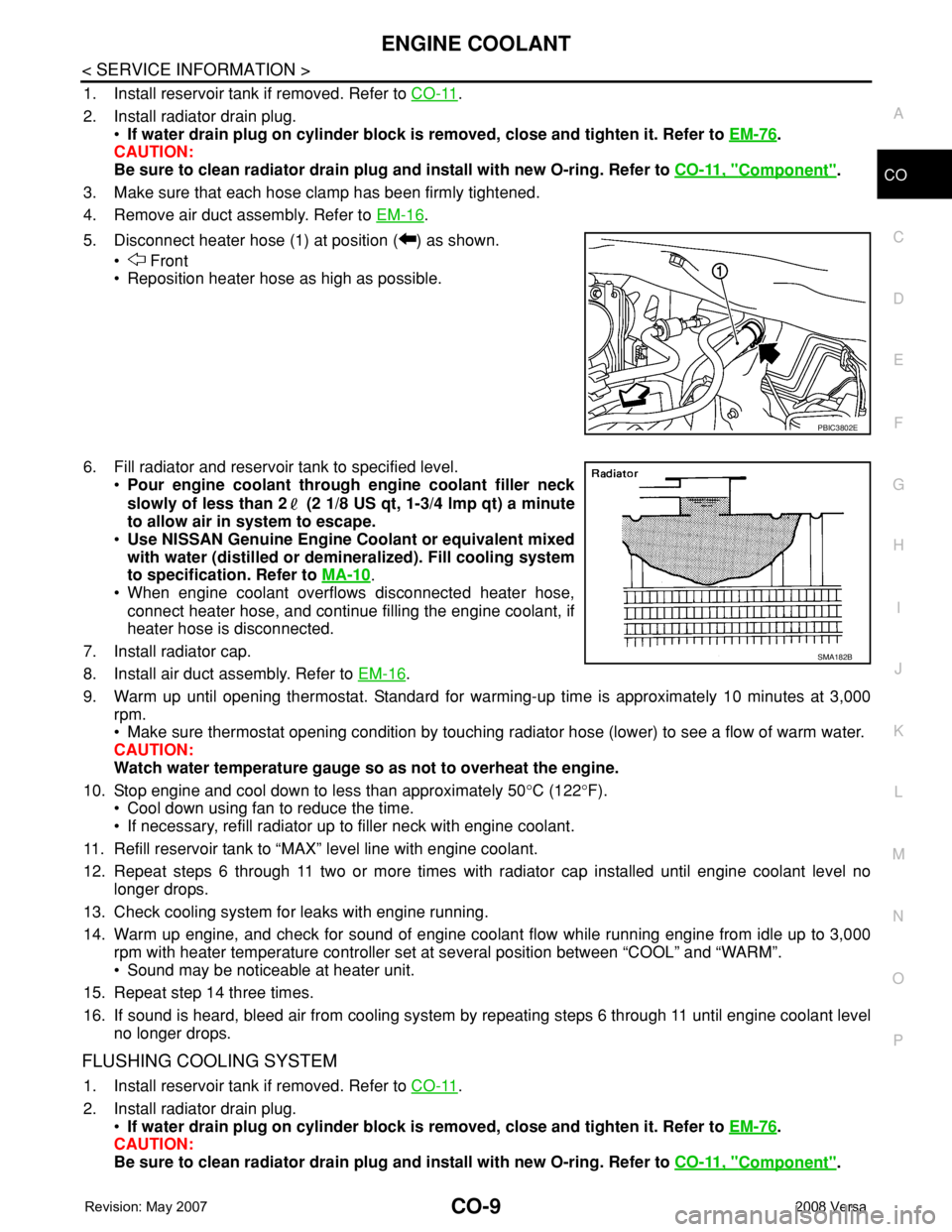
5. Disconnect heater hose (1) at position ( ) as shown.
• Front
• Reposition heater hose as high as possible.
6. Fill radiator and reservoir tank to specified level.
•Pour engine coolant through engine coolant filler neck
slowly of less than 2 (2 1/8 US qt, 1-3/4 lmp qt) a minute
to allow air in system to escape.
•Use NISSAN Genuine Engine Coolant or equivalent mixed
with water (distilled or demineralized). Fill cooling system
to specification. Refer to MA-10
.
• When engine coolant overflows disconnected heater hose,
connect heater hose, and continue filling the engine coolant, if
heater hose is disconnected.
7. Install radiator cap.
8. Install air duct assembly. Refer to EM-16
.
9. Warm up until opening thermostat. Standard for warming-up time is approximately 10 minutes at 3,000
rpm.
• Make sure thermostat opening condition by touching radiator hose (lower) to see a flow of warm water.
CAUTION:
Watch water temperature gauge so as not to overheat the engine.
10. Stop engine and cool down to less than approximately 50°C (122°F).
• Cool down using fan to reduce the time.
• If necessary, refill radiator up to filler neck with engine coolant.
11. Refill reservoir tank to “MAX” level line with engine coolant.
12. Repeat steps 6 through 11 two or more times with radiator cap installed until engine coolant level no
longer drops.
13. Check cooling system for leaks with engine running.
14. Warm up engine, and check for sound of engine coolant flow while running engine from idle up to 3,000
rpm with heater temperature controller set at several position between “COOL” and “WARM”.
• Sound may be noticeable at heater unit.
15. Repeat step 14 three times.
16. If sound is heard, bleed air from cooling system by repeating steps 6 through 11 until engine coolant level
no longer drops.
FLUSHING COOLING SYSTEM
1. Install reservoir tank if removed. Refer to CO-11.
2. Install radiator drain plug.
•If water drain plug on cylinder block is removed, close and tighten it. Refer to EM-76
.
CAUTION:
Be sure to clean radiator drain plug and install with new O-ring. Refer to CO-11, "
Component".
PBIC3802E
SMA182B
Page 832 of 2771
COOLING FAN
CO-15
< SERVICE INFORMATION >
C
D
E
F
G
H
I
J
K
L
MA
CO
N
P O
Removal and InstallationINFOID:0000000001702537
REMOVAL
1. Drain engine coolant from radiator. Refer to CO-8, "Changing Engine Coolant".
CAUTION:
• Perform this step when engine is cold.
• Do not spill engine coolant on drive belt.
2. Remove air duct (inlet). Refer to EM-16, "
Component".
3. Remove reservoir tank. Refer to CO-11, "
Component".
4. Disconnect radiator hose (upper) at radiator side. Refer to CO-11, "
Component".
5. Disconnect harness connectors from fan motor, and move harness to aside.
6. Remove cooling fan assembly.
CAUTION:
Be careful not to damage or scratch the radiator core.
INSTALLATION
Installation is the reverse order of removal.
• Cooling fans are controlled by ECM. For details, refer to EC-412
.
CAUTION:
Be careful not to damage or scratch the radiator core.
DISASSEMBLY AND ASSEMBLYINFOID:0000000001702538
Disassembly
1. Remove cooling fan from fan motor.
2. Remove fan motor from fan shroud.
Inspection After Disassembly
Inspect cooling fan for crack or unusual bend.
• If anything is found, replace cooling fan.
Assembly
Assembly is the reverse order of disassembly.
Page 836 of 2771
WATER OUTLET AND WATER CONTROL VALVE
CO-19
< SERVICE INFORMATION >
C
D
E
F
G
H
I
J
K
L
MA
CO
N
P O
WATER OUTLET AND WATER CONTROL VALVE
ComponentINFOID:0000000001702543
Removal and InstallationINFOID:0000000001702544
REMOVAL
1. Drain engine coolant. Refer to CO-8, "Changing Engine Coolant".
CAUTION:
Perform this step when the engine is cold.
2. Remove air duct. Refer to EM-16, "
Component".
3. Remove radiator hose (upper). Refer to CO-11, "
Component".
4. Remove heater hoses and water hoses.
5. Remove water outlet.
6. Remove water control valve.
7. Remove engine coolant temperature sensor, if necessary.
CAUTION:
• Handle carefully to avoid any shock to engine coolant temperature sensor.
• Replace the gasket with a new one.
INSPECTION AFTER REMOVAL
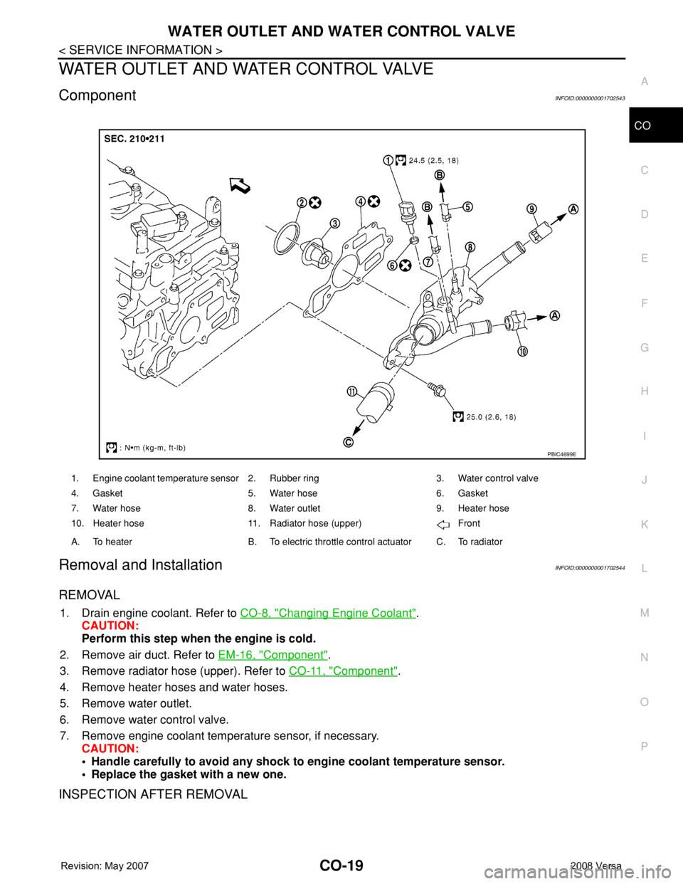
1. Engine coolant temperature sensor 2. Rubber ring 3. Water control valve
4. Gasket 5. Water hose 6. Gasket
7. Water hose 8. Water outlet 9. Heater hose
10. Heater hose 11. Radiator hose (upper) Front
A. To heater B. To electric throttle control actuator C. To radiator
PBIC4699E
Page 838 of 2771
WATER OUTLET AND WATER CONTROL VALVE
CO-21
< SERVICE INFORMATION >
C
D
E
F
G
H
I
J
K
L
MA
CO
N
P O
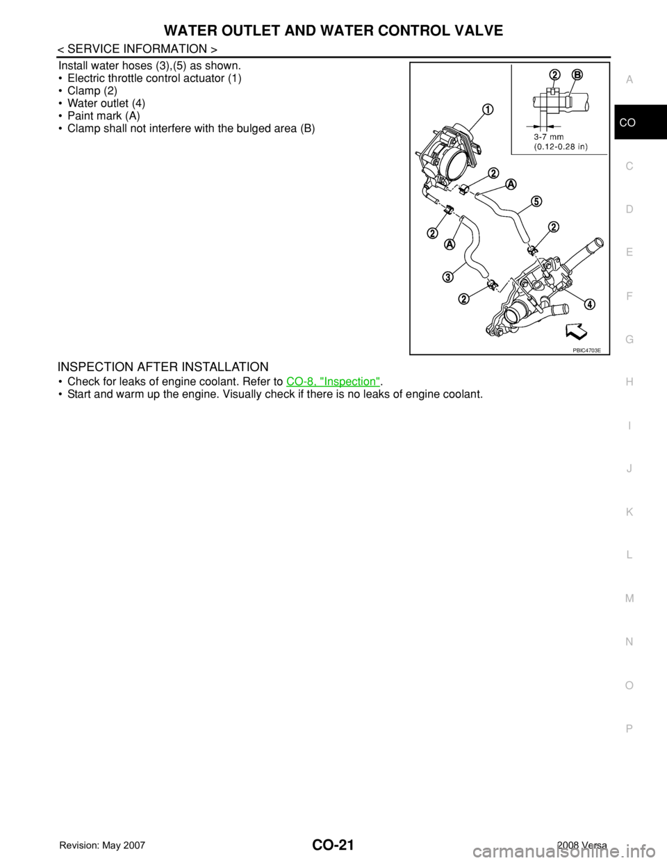
Install water hoses (3),(5) as shown.
• Electric throttle control actuator (1)
• Clamp (2)
• Water outlet (4)
• Paint mark (A)
• Clamp shall not interfere with the bulged area (B)
INSPECTION AFTER INSTALLATION
• Check for leaks of engine coolant. Refer to CO-8, "Inspection".
• Start and warm up the engine. Visually check if there is no leaks of engine coolant.
PBIC4703E
Page 839 of 2771

CO-22
< SERVICE INFORMATION >
SERVICE DATA AND SPECIFICATIONS (SDS)
SERVICE DATA AND SPECIFICATIONS (SDS)
Standard and LimitINFOID:0000000001702545
CAPACITY
Unit: (US qt, lmp qt)
THERMOSTAT
WATER CONTROL VALVE
RADIATOR
Unit: kPa (bar, kg/cm2, psi)
Engine coolant capacity (with reservoir tank at “MAX” level) Approx. 6.8 (7 1/4, 6.0)
Valve opening temperature 80.5 - 83.5°C (177 - 182°F)
Maximum valve lift 8 mm/ 95°C (0.315 in/ 203°F)
Valve closing temperature 77°C (171°F)
Valve opening temperature 93.5 - 96.5°C (200 - 206°F)
Maximum valve lift 8 mm/ 108°C (0.315 in/ 226°F)
Valve closing temperature 90°C (194°F)
Cap relief pressureStandard 78 - 98 (0.78 - 0.98, 0.8 - 1.0, 11- 14)
Limit 59 (0.59, 0.6, 9)
Leakage test pressure 157 (1.57, 1.6, 23)
Page 840 of 2771
CVT-1
TRANSMISSION/TRANSAXLE
D
E
F
G
H
I
J
K
L
M
SECTION CVT
A
B
CVT
N
O
P
CONTENTS
CVT
SERVICE INFORMATION ............................5
INDEX FOR DTC .................................................5
Alphabetical Index .....................................................5
DTC No. Index ..........................................................5
PRECAUTIONS ...................................................7
Precaution for Supplemental Restraint System
(SRS) "AIR BAG" and "SEAT BELT PRE-TEN-
SIONER" ...................................................................
7
Precaution Necessary for Steering Wheel Rota-
tion After Battery Disconnect .....................................
7
Precaution for On Board Diagnosis (OBD) System
of CVT and Engine ....................................................
7
Service After Replacing TCM and Transaxle As-
sembly .......................................................................
8
Removal and Installation Procedure for CVT Unit
Connector ..................................................................
9
Precaution ...............................................................10
Service Notice or Precaution ...................................11
PREPARATION ..................................................12
Special Service Tool ...............................................12
Commercial Service Tool ........................................12
CVT FLUID .........................................................13
Checking CVT Fluid ................................................13
Changing CVT Fluid ................................................14
CVT Fluid Cooler Cleaning .....................................14
CVT SYSTEM .....................................................18
Cross-Sectional View - RE0F08A ...........................18
Control System ........................................................19
Hydraulic Control System ........................................20
TCM Function ..........................................................20
CAN Communication ...............................................21
Input/Output Signal of TCM .....................................22
Line Pressure and Secondary Pressure Control .....22
Shift Control ............................................................23
Lock-up and Select Control .....................................24
Control Valve ...........................................................25
ON BOARD DIAGNOSTIC (OBD) SYSTEM ....26
Introduction ..............................................................26
OBD-II Function for CVT System ............................26
One or Two Trip Detection Logic of OBD-II .............26
OBD-II Diagnostic Trouble Code (DTC) ..................26
Malfunction Indicator Lamp (MIL) ............................27
TROUBLE DIAGNOSIS ....................................29
DTC Inspection Priority Chart ..................................29
Fail-Safe ..................................................................29
How to Perform Trouble Diagnosis for Quick and
Accurate Repair .......................................................
30
CVT Electrical Parts Location ..................................35
Circuit Diagram ........................................................36
Inspections before Trouble Diagnosis .....................36
Road Test ................................................................40
Check before Engine Is Started ...............................41
Check at Idle ............................................................41
Cruise Test ..............................................................43
Vehicle Speed When Shifting Gears .......................45
TCM Terminal and Reference Value .......................45
CONSULT-III Function (TRANSMISSION) ..............47
Diagnosis Procedure without CONSULT-III ............55
DTC U1000 CAN COMMUNICATION LINE .....56
Description ...............................................................56
On Board Diagnosis Logic .......................................56
Possible Cause ........................................................56
DTC Confirmation Procedure ..................................56
Wiring Diagram - CVT - CAN ...................................57
Diagnosis Procedure ...............................................58
DTC U1010 TRANSMISSION CONTROL
MODULE (CAN) ................................................
59
Description ...............................................................59
On Board Diagnosis Logic .......................................59
Possible Cause ........................................................59
DTC Confirmation Procedure ..................................59
Diagnosis Procedure ...............................................59
DTC P0615 START SIGNAL CIRCUIT .............60