2008 NISSAN TIIDA PN switch
[x] Cancel search: PN switchPage 650 of 2771

BL-216
< SERVICE INFORMATION >
NATS (NISSAN ANTI-THEFT SYSTEM)
1.STARTING ENGINE
Check if the engine could be started by inserting the mechanical key into the ignition key cylinder and operate
ignition switch.
OK >> System is normal.
NG >> GO TO 2.
2.PERFORM SELF DIAGNOSIS
Perform SELF-DIAGNOSIS “NATS V5.0” using CONSULT-III.
NOTE:
NATS program card is necessary to display the “SELF-DIAGNOSIS”.
No malfunction is detected>>Recheck the starting engine section GO TO 1.
Malfunction related to NATS is detected>>GO TO 3.
Malfunctions related to “DON’T ERASE BEFORE CHECKING ENG DIAG” and NATS are detected>>GO
TO 7.
3.IDENTIFYING NATS MALFUNCTION
Self-diagnosis results referring to NATS, but no information about engine self-diagnosis result is displayed on
CONSULT-III. Refer to BL-217, "
Trouble Diagnosis" .
>> GO TO 4.
4.NATS TROUBLE DIAGNOSIS
Repair NATS (if necessary, perform “C/U INITIALIZATION” with CONSULT-III.)
>> GO TO 5.
5.ERASE SELF-DIAGNOSIS
Erase the record of “SELF-DIAGNOSIS” by using CONSULT-III.
>> GO TO 6.
6.STARTING ENGINE
Check if the engine could be started by inserting the mechanical key into the ignition key cylinder and operate
ignition switch.
NG >> GO TO 2.
OK >> End of inspection.
7.IDENTIFYING NATS AND ENGINE CONTROL MALFUNCTION
NATS malfunction and “DON’T ERASE BEFORE CHECKING ENG DIAG” are displayed on the CONSULT-III
screen.
NOTE:
This indication means that malfunction have been detected in NATS and engine control system.
>> GO TO 8.
8.NATS TROUBLE DIAGNOSIS
Repair NATS according to self-diagnosis results refer to NATS (if necessary, perform “C/U INITIALZATIN” with
CONSULT-III.)
NOTE:
Do not erase “SELF-DIAGNOSIS” by using CONSULT-III.
>> GO TO 9.
Page 651 of 2771

NATS (NISSAN ANTI-THEFT SYSTEM)
BL-217
< SERVICE INFORMATION >
C
D
E
F
G
H
J
K
L
MA
B
BL
N
O
P
9.IDENTIFYING ENGINE CONTROL MALFUNCTION
Check engine “SELF-DIAGNOSIS” records with a generalized program card instead of the NATS program
card.
>> GO TO 10.
10.ENGINE CONTROL SYSTEM TROUBLE DIAGNOSIS
Repair engine control system if engine related malfunction is detected.
With engine diagnostic codes present, refer to EC-9
.
Without engine diagnostic codes present, refer to EC-81
.
NOTE:
If only “NATS MALFUNCTION” is displayed, erase the self-diagnosis results.
>> GO TO 11.
11 .STARTING ENGINE
Check if the engine could be started by inserting the mechanical key into the ignition key cylinder and operate
ignition switch.
OK >> GO TO 12.
NG >> GO TO 2.
12.ERASE SELF-DIAGNOSIS
Erase both NATS and ENGINE "SELF-DIAGNOSIS" records by using CONSULT-III NATS program card and
generalized program card.
>> GO TO 13
13.COMFIRMATION
Perform running test with CONSULT-III in engine “SELF-DIAGNOSIS” mode.
“NO DTC” is displayed>> End of inspection.
Malfunction information is displayed>>GO TO 2.
Trouble DiagnosisINFOID:0000000001704111
SYMPTOM MATRIX CHART 1
Page 653 of 2771
NATS (NISSAN ANTI-THEFT SYSTEM)
BL-219
< SERVICE INFORMATION >
C
D
E
F
G
H
J
K
L
MA
B
BL
N
O
P
In rare case, “CHAIN OF ECM-IMMU” might be stored during key registration procedure, even if the system is
not malfunctioning.
Is
“CHAIN OF ECM-IMMU” displayed?
Yes >> GO TO 2.
No >> GO TO BL-217, "
Trouble Diagnosis" .
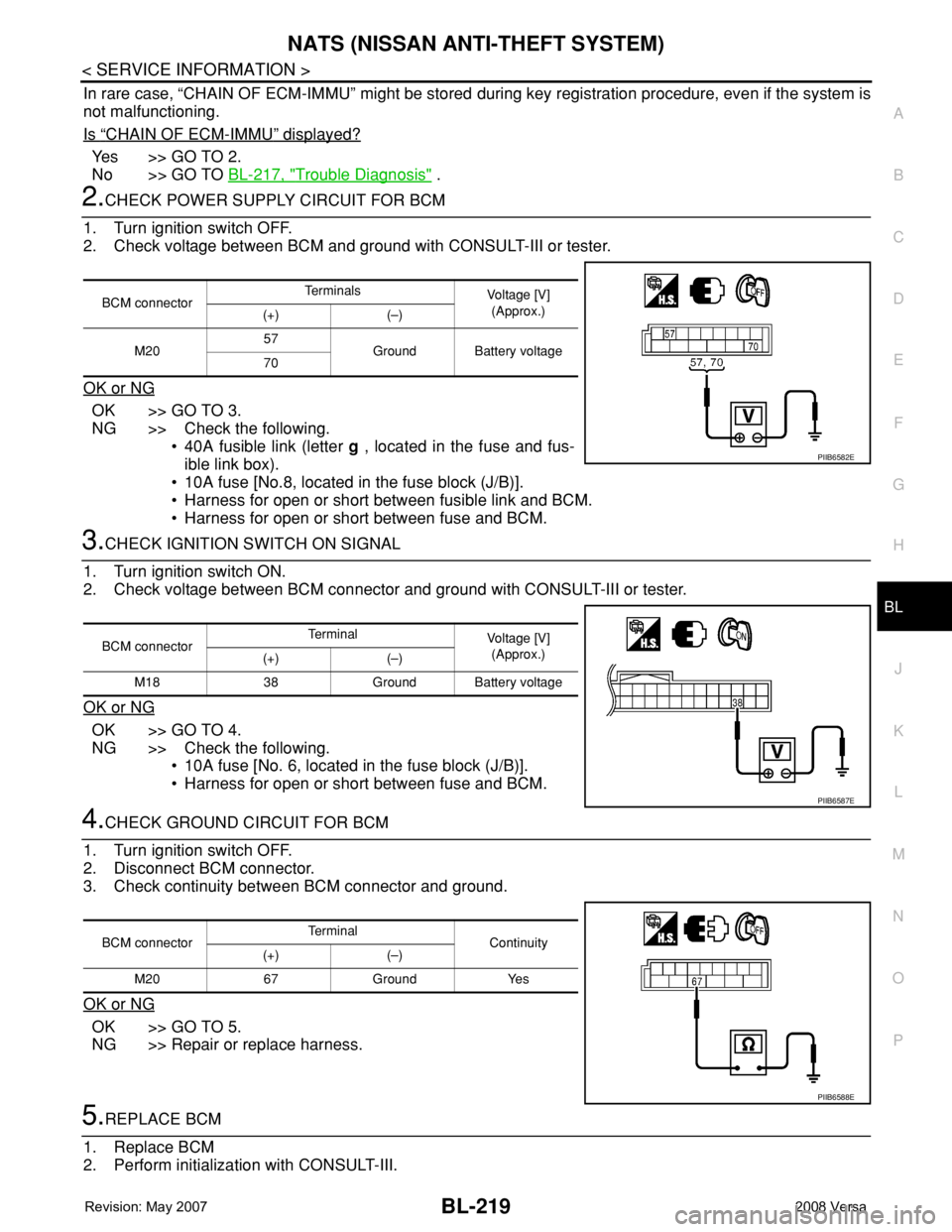
2.CHECK POWER SUPPLY CIRCUIT FOR BCM
1. Turn ignition switch OFF.
2. Check voltage between BCM and ground with CONSULT-III or tester.
OK or NG
OK >> GO TO 3.
NG >> Check the following.
• 40A fusible link (letter g , located in the fuse and fus-
ible link box).
• 10A fuse [No.8, located in the fuse block (J/B)].
• Harness for open or short between fusible link and BCM.
• Harness for open or short between fuse and BCM.
3.CHECK IGNITION SWITCH ON SIGNAL
1. Turn ignition switch ON.
2. Check voltage between BCM connector and ground with CONSULT-III or tester.
OK or NG
OK >> GO TO 4.
NG >> Check the following.
• 10A fuse [No. 6, located in the fuse block (J/B)].
• Harness for open or short between fuse and BCM.
4.CHECK GROUND CIRCUIT FOR BCM
1. Turn ignition switch OFF.
2. Disconnect BCM connector.
3. Check continuity between BCM connector and ground.
OK or NG
OK >> GO TO 5.
NG >> Repair or replace harness.
5.REPLACE BCM
1. Replace BCM
2. Perform initialization with CONSULT-III.
BCM connectorTe r m i n a l s
Voltage [V]
(Approx.)
(+) (–)
M2057
Ground Battery voltage
70
PIIB6582E
BCM connectorTerminal
Voltage [V]
(Approx.)
(+) (–)
M18 38 Ground Battery voltage
PIIB6587E
BCM connectorTerminal
Continuity
(+) (–)
M20 67 Ground Yes
PIIB6588E
Page 654 of 2771
BL-220
< SERVICE INFORMATION >
NATS (NISSAN ANTI-THEFT SYSTEM)
For initialization, refer to “CONSULT-III Operation Manual NATS”.
Does the engine start?
Yes >> BCM is malfunctioning.
• Replace BCM. Refer to BCS-18, "
Removal and Installation of BCM" .
• Perform initialization with CONSULT-III
• For initialization, refer to “CONSULT-III Operation Manual NATS”
No >> ECM is malfunctioning.
• Replace ECM.
• Perform initialization or re-communicating function
• For initialization, refer to “CONSULT-III Operation Manual NATS”
• For re-communicating function, refer to BL-211, "
ECM Re-communicating Function"
Diagnosis Procedure 2INFOID:0000000001704113
Self-diagnostic results:
“CHAIN OF IMMU-KEY” displayed on CONSULT-III screen
1.CONFIRM SELF-DIAGNOSTIC RESULTS
Confirm SELF-DIAGNOSTIC RESULTS “CHAIN OF IMMU-KEY” displayed on CONSULT-III screen.
Is
“CHAIN OF IMMU-KEY” displayed?
Ye s > > G O T O 2 .
No >> GO TO BL-217, "
Trouble Diagnosis" .
2.CHECK NATS ANTENNA AMP. INSTALLATION
Check NATS antenna amp. installation. Refer to BL-224, "
How to Replace NATS Antenna Amp" .
OK or NG
OK >> GO TO 3.
NG >> Reinstall NATS antenna amp. correctly.
3.CHECK NATS IGNITION KEY ID CHIP
Start engine with another registered NATS ignition key.
Does the engine start?
Yes >> Ignition key ID chip is malfunctioning.
• Replace the ignition key
• Perform initialization with CONSULT-III
For initialization, refer to “CONSULT-III Operation Manual NATS”
No >> GO TO 4.
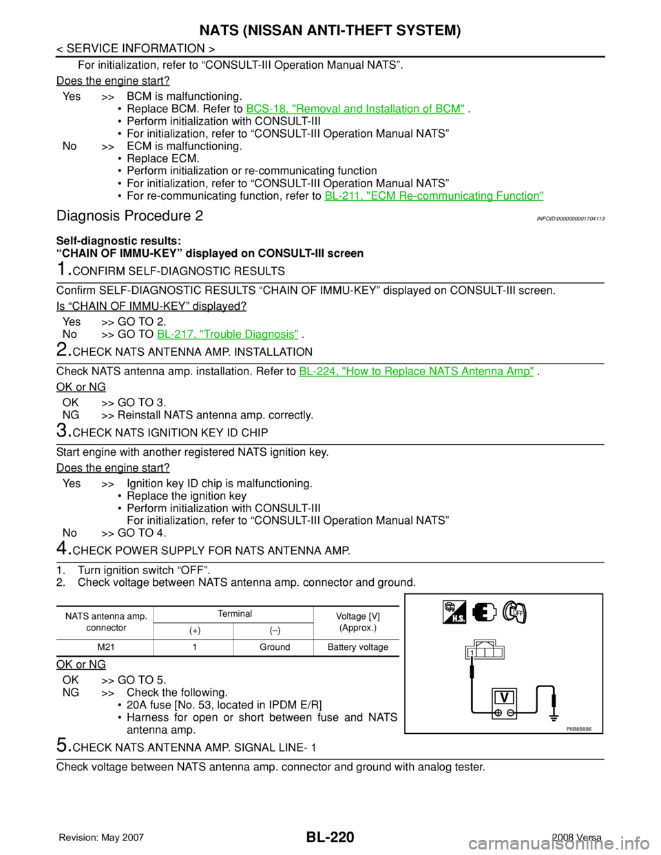
4.CHECK POWER SUPPLY FOR NATS ANTENNA AMP.
1. Turn ignition switch “OFF”.
2. Check voltage between NATS antenna amp. connector and ground.
OK or NG
OK >> GO TO 5.
NG >> Check the following.
• 20A fuse [No. 53, located in IPDM E/R]
• Harness for open or short between fuse and NATS
antenna amp.
5.CHECK NATS ANTENNA AMP. SIGNAL LINE- 1
Check voltage between NATS antenna amp. connector and ground with analog tester.
NATS antenna amp.
connectorTe r m i n a l
Voltage [V]
(Approx.)
(+) (–)
M21 1 Ground Battery voltage
PIIB6589E
Page 655 of 2771
NATS (NISSAN ANTI-THEFT SYSTEM)
BL-221
< SERVICE INFORMATION >
C
D
E
F
G
H
J
K
L
MA
B
BL
N
O
P
OK or NG
OK >> GO TO 6.
NG >> • Check harness for open or short between NATS antenna amp. and BCM.
NOTE:
If harness is OK, replace BCM, perform initialization with CONSULT-III. For initialization, refer to
“CONSULT-III Operation Manual NATS”.
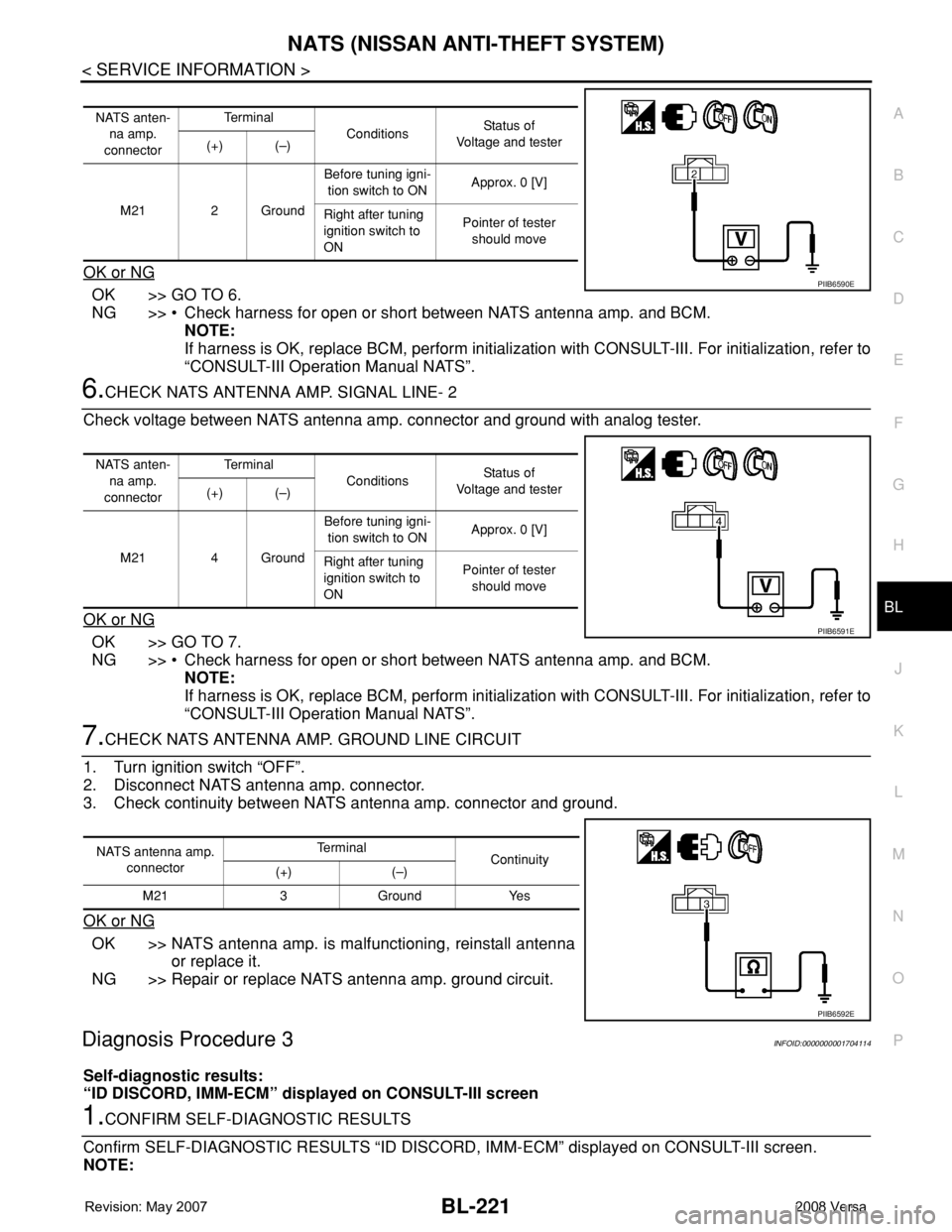
6.CHECK NATS ANTENNA AMP. SIGNAL LINE- 2
Check voltage between NATS antenna amp. connector and ground with analog tester.
OK or NG
OK >> GO TO 7.
NG >> • Check harness for open or short between NATS antenna amp. and BCM.
NOTE:
If harness is OK, replace BCM, perform initialization with CONSULT-III. For initialization, refer to
“CONSULT-III Operation Manual NATS”.
7.CHECK NATS ANTENNA AMP. GROUND LINE CIRCUIT
1. Turn ignition switch “OFF”.
2. Disconnect NATS antenna amp. connector.
3. Check continuity between NATS antenna amp. connector and ground.
OK or NG
OK >> NATS antenna amp. is malfunctioning, reinstall antenna
or replace it.
NG >> Repair or replace NATS antenna amp. ground circuit.
Diagnosis Procedure 3INFOID:0000000001704114
Self-diagnostic results:
“ID DISCORD, IMM-ECM” displayed on CONSULT-III screen
1.CONFIRM SELF-DIAGNOSTIC RESULTS
Confirm SELF-DIAGNOSTIC RESULTS “ID DISCORD, IMM-ECM” displayed on CONSULT-III screen.
NOTE:
NATS anten-
na amp.
connectorTe r m i n a l
ConditionsStatus of
Voltage and tester
(+) (–)
M21 2 GroundBefore tuning igni-
tion switch to ONApprox. 0 [V]
Right after tuning
ignition switch to
ONPointer of tester
should move
PIIB6590E
NATS anten-
na amp.
connectorTe r m i n a l
ConditionsStatus of
Voltage and tester
(+) (–)
M21 4 GroundBefore tuning igni-
tion switch to ONApprox. 0 [V]
Right after tuning
ignition switch to
ONPointer of tester
should move
PIIB6591E
NATS antenna amp.
connectorTe r m i n a l
Continuity
(+) (–)
M21 3 Ground Yes
PIIB6592E
Page 656 of 2771
BL-222
< SERVICE INFORMATION >
NATS (NISSAN ANTI-THEFT SYSTEM)
“ID DISCORD IMM-ECM”:
Registered ID of BCM is in discord with that of ECM.
Is
“ID DISCORD IMM-ECM” displayed?
Ye s > > G O T O 2 .
No >> GO TO BL-217, "
Trouble Diagnosis" .
2.PERFORM INITIALIZATION WITH CONSULT-III
Perform initialization with CONSULT-III. Re-register all NATS ignition key IDs.
For initialization, refer to “CONSULT-III Operation Manual NATS”.
NOTE:
If the initialization is not completed or malfunctions, CONSULT-III shows message on the screen.
Can the system be initialized?
Yes >> • Start engine. (END)
• (System initialization had not been completed.)
No >> ECM is malfunctioning.
• Replace ECM.
• Perform initialization with CONSULT-III
For initialization, refer to “CONSULT-III Operation Manual NATS”
Diagnosis Procedure 4INFOID:0000000001704115
“COMBINATION METER (SECURITY) DOES NOT LIGHT UP”
1.CHECK FUSE
Check 10A fuse [No.13, located in the fuse block (J/B)]
OK or NG
OK >> GO TO 2.
NG >> Replace fuse.
2.CHECK COMBINATION METER (SECURITY)
1. Install 10A fuse.
2. Start engine and turn ignition switch OFF.
3. Check if the combination meter (security) lights up.
OK or NG
OK >> INSPECTION END.
NG >> GO TO 3.
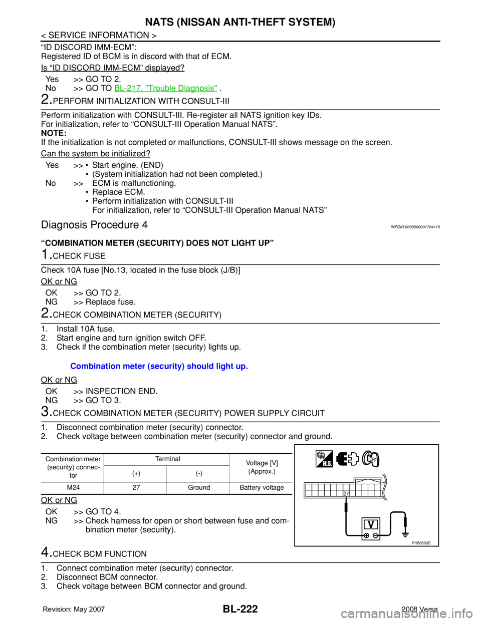
3.CHECK COMBINATION METER (SECURITY) POWER SUPPLY CIRCUIT
1. Disconnect combination meter (security) connector.
2. Check voltage between combination meter (security) connector and ground.
OK or NG
OK >> GO TO 4.
NG >> Check harness for open or short between fuse and com-
bination meter (security).
4.CHECK BCM FUNCTION
1. Connect combination meter (security) connector.
2. Disconnect BCM connector.
3. Check voltage between BCM connector and ground. Combination meter (security) should light up.
Combination meter
(security) connec-
torTe r m i n a l
Voltage [V]
(Approx.)
(+) (-)
M24 27 Ground Battery voltage
PIIB6593E
Page 657 of 2771
NATS (NISSAN ANTI-THEFT SYSTEM)
BL-223
< SERVICE INFORMATION >
C
D
E
F
G
H
J
K
L
MA
B
BL
N
O
P
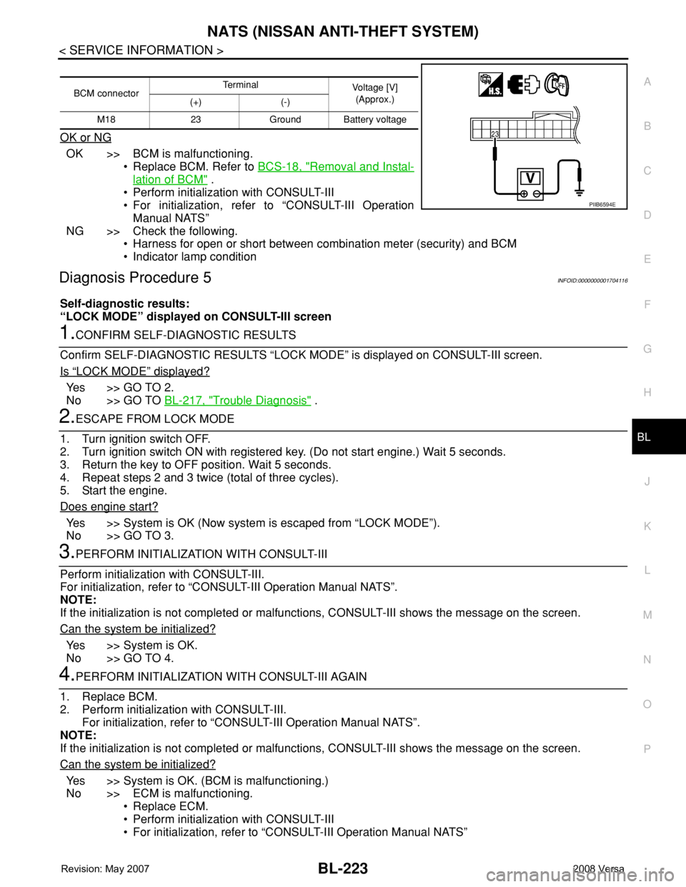
OK or NG
OK >> BCM is malfunctioning.
• Replace BCM. Refer to BCS-18, "
Removal and Instal-
lation of BCM" .
• Perform initialization with CONSULT-III
• For initialization, refer to “CONSULT-III Operation
Manual NATS”
NG >> Check the following.
• Harness for open or short between combination meter (security) and BCM
• Indicator lamp condition
Diagnosis Procedure 5INFOID:0000000001704116
Self-diagnostic results:
“LOCK MODE” displayed on CONSULT-III screen
1.CONFIRM SELF-DIAGNOSTIC RESULTS
Confirm SELF-DIAGNOSTIC RESULTS “LOCK MODE” is displayed on CONSULT-III screen.
Is
“LOCK MODE” displayed?
Yes >> GO TO 2.
No >> GO TO BL-217, "
Trouble Diagnosis" .
2.ESCAPE FROM LOCK MODE
1. Turn ignition switch OFF.
2. Turn ignition switch ON with registered key. (Do not start engine.) Wait 5 seconds.
3. Return the key to OFF position. Wait 5 seconds.
4. Repeat steps 2 and 3 twice (total of three cycles).
5. Start the engine.
Does engine start?
Yes >> System is OK (Now system is escaped from “LOCK MODE”).
No >> GO TO 3.
3.PERFORM INITIALIZATION WITH CONSULT-III
Perform initialization with CONSULT-III.
For initialization, refer to “CONSULT-III Operation Manual NATS”.
NOTE:
If the initialization is not completed or malfunctions, CONSULT-III shows the message on the screen.
Can the system be initialized?
Yes >> System is OK.
No >> GO TO 4.
4.PERFORM INITIALIZATION WITH CONSULT-III AGAIN
1. Replace BCM.
2. Perform initialization with CONSULT-III.
For initialization, refer to “CONSULT-III Operation Manual NATS”.
NOTE:
If the initialization is not completed or malfunctions, CONSULT-III shows the message on the screen.
Can the system be initialized?
Yes >> System is OK. (BCM is malfunctioning.)
No >> ECM is malfunctioning.
• Replace ECM.
• Perform initialization with CONSULT-III
• For initialization, refer to “CONSULT-III Operation Manual NATS”
BCM connectorTerminal
Voltage [V]
(Approx.)
(+) (-)
M18 23 Ground Battery voltage
PIIB6594E
Page 733 of 2771
BR-2
< SERVICE INFORMATION >
PRECAUTIONS
SERVICE INFORMATION
PRECAUTIONS
Precaution for Supplemental Restraint System (SRS) "AIR BAG" and "SEAT BELT
PRE-TENSIONER"
INFOID:0000000001703775
The Supplemental Restraint System such as “AIR BAG” and “SEAT BELT PRE-TENSIONER”, used along
with a front seat belt, helps to reduce the risk or severity of injury to the driver and front passenger for certain
types of collision. This system includes seat belt switch inputs and dual stage front air bag modules. The SRS
system uses the seat belt switches to determine the front air bag deployment, and may only deploy one front
air bag, depending on the severity of a collision and whether the front occupants are belted or unbelted.
Information necessary to service the system safely is included in the SRS and SB section of this Service Man-
ual.
WARNING:
• To avoid rendering the SRS inoperative, which could increase the risk of personal injury or death in
the event of a collision which would result in air bag inflation, all maintenance must be performed by
an authorized NISSAN/INFINITI dealer.
• Improper maintenance, including incorrect removal and installation of the SRS, can lead to personal
injury caused by unintentional activation of the system. For removal of Spiral Cable and Air Bag
Module, see the SRS section.
• Do not use electrical test equipment on any circuit related to the SRS unless instructed to in this
Service Manual. SRS wiring harnesses can be identified by yellow and/or orange harnesses or har-
ness connectors.
Precaution for Brake SystemINFOID:0000000001703776
• Refill using recommended brake fluid. Refer to MA-10.
• Never reuse drained brake fluid.
• Be careful not to splash brake fluid on painted surface of body. If brake fluid is splashed on painted surfaces
of body immediately wipe it off with cloth and then wash it away with water.
• To clean or wash all parts of master cylinder, disc brake caliper and wheel cylinder, use new brake fluid.
• Never use mineral oils such as gasoline or kerosene. They will ruin rubber parts of the hydraulic system.
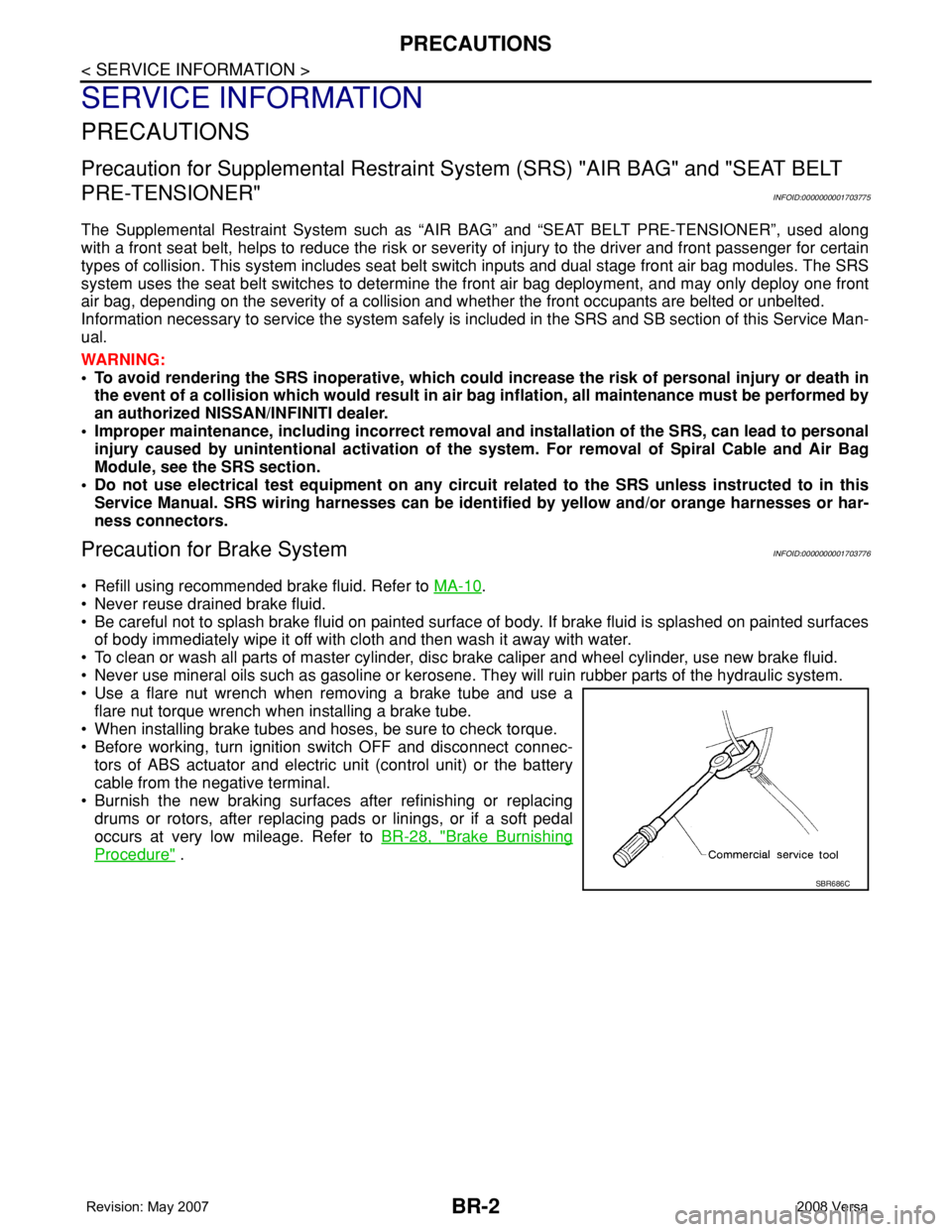
• Use a flare nut wrench when removing a brake tube and use a
flare nut torque wrench when installing a brake tube.
• When installing brake tubes and hoses, be sure to check torque.
• Before working, turn ignition switch OFF and disconnect connec-
tors of ABS actuator and electric unit (control unit) or the battery
cable from the negative terminal.
• Burnish the new braking surfaces after refinishing or replacing
drums or rotors, after replacing pads or linings, or if a soft pedal
occurs at very low mileage. Refer toBR-28, "
Brake Burnishing
Procedure" .
SBR686C