2008 NISSAN TIIDA PN switch
[x] Cancel search: PN switchPage 796 of 2771
![NISSAN TIIDA 2008 Service Repair Manual TROUBLE DIAGNOSES FOR SYMPTOMS
BRC-31
< SERVICE INFORMATION >[ABS]
C
D
E
G
H
I
J
K
L
MA
B
BRC
N
O
P
NO >> GO TO 2.
2.RECHECK SYMPTOM
Does the symptom occur only when electrical equipment switches (suc NISSAN TIIDA 2008 Service Repair Manual TROUBLE DIAGNOSES FOR SYMPTOMS
BRC-31
< SERVICE INFORMATION >[ABS]
C
D
E
G
H
I
J
K
L
MA
B
BRC
N
O
P
NO >> GO TO 2.
2.RECHECK SYMPTOM
Does the symptom occur only when electrical equipment switches (suc](/manual-img/5/57399/w960_57399-795.png)
TROUBLE DIAGNOSES FOR SYMPTOMS
BRC-31
< SERVICE INFORMATION >[ABS]
C
D
E
G
H
I
J
K
L
MA
B
BRC
N
O
P
NO >> GO TO 2.
2.RECHECK SYMPTOM
Does the symptom occur only when electrical equipment switches (such as headlamps) are turned on?
YES >> Check for radio, antenna or related wiring that is routed too close to the ABS actuator and electric
unit (control unit) and reroute as necessary.
NO >> Go to BRC-29, "
ABS Works Frequently".
Page 803 of 2771
CL-2
< SERVICE INFORMATION >
PRECAUTIONS
SERVICE INFORMATION
PRECAUTIONS
Precaution for Supplemental Restraint System (SRS) "AIR BAG" and "SEAT BELT
PRE-TENSIONER"
INFOID:0000000001703112
The Supplemental Restraint System such as “AIR BAG” and “SEAT BELT PRE-TENSIONER”, used along
with a front seat belt, helps to reduce the risk or severity of injury to the driver and front passenger for certain
types of collision. This system includes seat belt switch inputs and dual stage front air bag modules. The SRS
system uses the seat belt switches to determine the front air bag deployment, and may only deploy one front
air bag, depending on the severity of a collision and whether the front occupants are belted or unbelted.
Information necessary to service the system safely is included in the SRS and SB section of this Service Man-
ual.
WARNING:
• To avoid rendering the SRS inoperative, which could increase the risk of personal injury or death in
the event of a collision which would result in air bag inflation, all maintenance must be performed by
an authorized NISSAN/INFINITI dealer.
• Improper maintenance, including incorrect removal and installation of the SRS, can lead to personal
injury caused by unintentional activation of the system. For removal of Spiral Cable and Air Bag
Module, see the SRS section.
• Do not use electrical test equipment on any circuit related to the SRS unless instructed to in this
Service Manual. SRS wiring harnesses can be identified by yellow and/or orange harnesses or har-
ness connectors.
Precaution for Procedure without Cowl Top CoverINFOID:0000000001843684
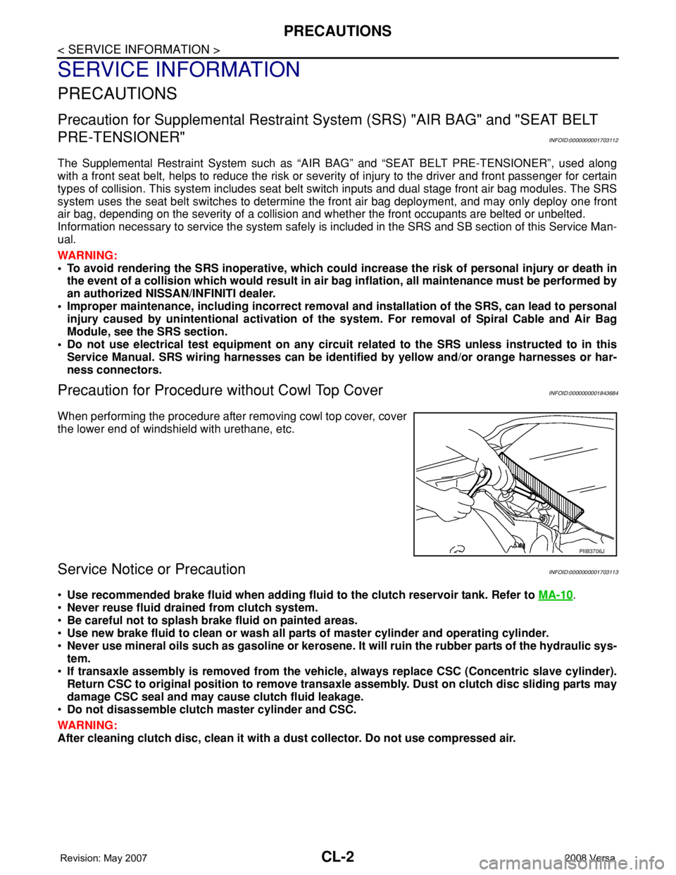
When performing the procedure after removing cowl top cover, cover
the lower end of windshield with urethane, etc.
Service Notice or PrecautionINFOID:0000000001703113
•Use recommended brake fluid when adding fluid to the clutch reservoir tank. Refer to MA-10.
•Never reuse fluid drained from clutch system.
•Be careful not to splash brake fluid on painted areas.
•Use new brake fluid to clean or wash all parts of master cylinder and operating cylinder.
•Never use mineral oils such as gasoline or kerosene. It will ruin the rubber parts of the hydraulic sys-
tem.
•If transaxle assembly is removed from the vehicle, always replace CSC (Concentric slave cylinder).
Return CSC to original position to remove transaxle assembly. Dust on clutch disc sliding parts may
damage CSC seal and may cause clutch fluid leakage.
•Do not disassemble clutch master cylinder and CSC.
WARNING:
After cleaning clutch disc, clean it with a dust collector. Do not use compressed air.
PIIB3706J
Page 806 of 2771
CLUTCH PEDAL
CL-5
< SERVICE INFORMATION >
D
E
F
G
H
I
J
K
L
MA
B
CL
N
O
P
CLUTCH PEDAL
On-vehicle Inspection and AdjustmentINFOID:0000000001703117
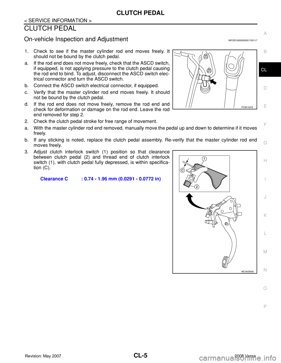
1. Check to see if the master cylinder rod end moves freely. It
should not be bound by the clutch pedal.
a. If the rod end does not move freely, check that the ASCD switch,
if equipped, is not applying pressure to the clutch pedal causing
the rod end to bind. To adjust, disconnect the ASCD switch elec-
trical connector and turn the ASCD switch.
b. Connect the ASCD switch electrical connector, if equipped.
c. Verify that the master cylinder rod end moves freely. It should
not be bound by the clutch pedal.
d. If the rod end does not move freely, remove the rod end and
check for deformation or damage on the rod end. Leave the rod
end removed for step 2.
2. Check the clutch pedal stroke for free range of movement.
a. With the master cylinder rod end removed, manually move the pedal up and down to determine if it moves
freely.
b. If any sticking is noted, replace the clutch pedal assembly. Re-verify that the master cylinder rod end
moves freely.
3. Adjust clutch interlock switch (1) position so that clearance
between clutch pedal (2) and thread end of clutch interlock
switch (1), with clutch pedal fully depressed, is within specifica-
tion (C).
Clearance C : 0.74 - 1.96 mm (0.0291 - 0.0772 in)
PCIB1491E
WCIA0594E
Page 807 of 2771
CL-6
< SERVICE INFORMATION >
CLUTCH PEDAL
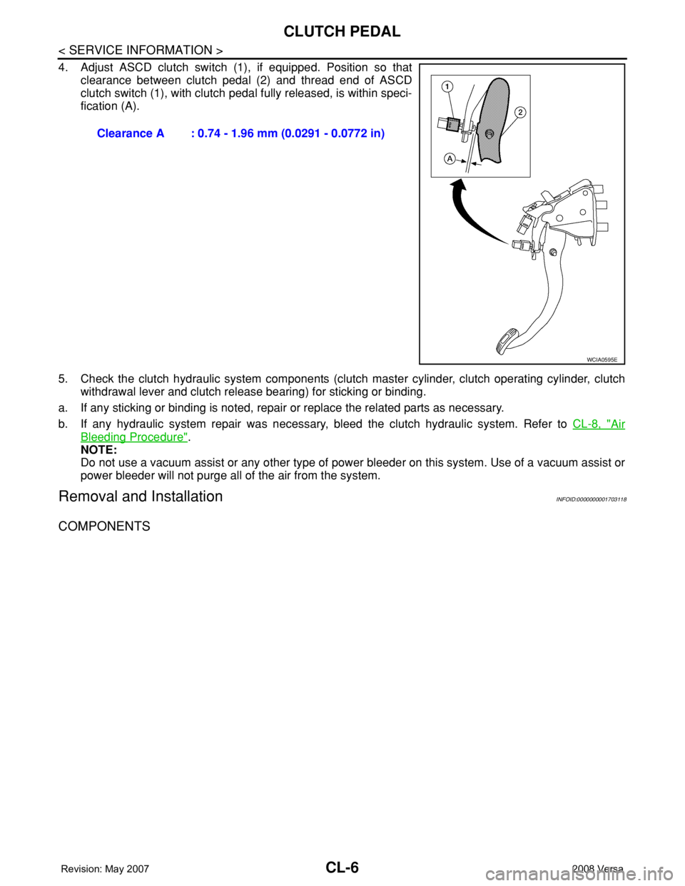
4. Adjust ASCD clutch switch (1), if equipped. Position so that
clearance between clutch pedal (2) and thread end of ASCD
clutch switch (1), with clutch pedal fully released, is within speci-
fication (A).
5. Check the clutch hydraulic system components (clutch master cylinder, clutch operating cylinder, clutch
withdrawal lever and clutch release bearing) for sticking or binding.
a. If any sticking or binding is noted, repair or replace the related parts as necessary.
b. If any hydraulic system repair was necessary, bleed the clutch hydraulic system. Refer to CL-8, "
Air
Bleeding Procedure".
NOTE:
Do not use a vacuum assist or any other type of power bleeder on this system. Use of a vacuum assist or
power bleeder will not purge all of the air from the system.
Removal and InstallationINFOID:0000000001703118
COMPONENTS
Clearance A : 0.74 - 1.96 mm (0.0291 - 0.0772 in)
WCIA0595E
Page 808 of 2771
CLUTCH PEDAL
CL-7
< SERVICE INFORMATION >
D
E
F
G
H
I
J
K
L
MA
B
CL
N
O
P
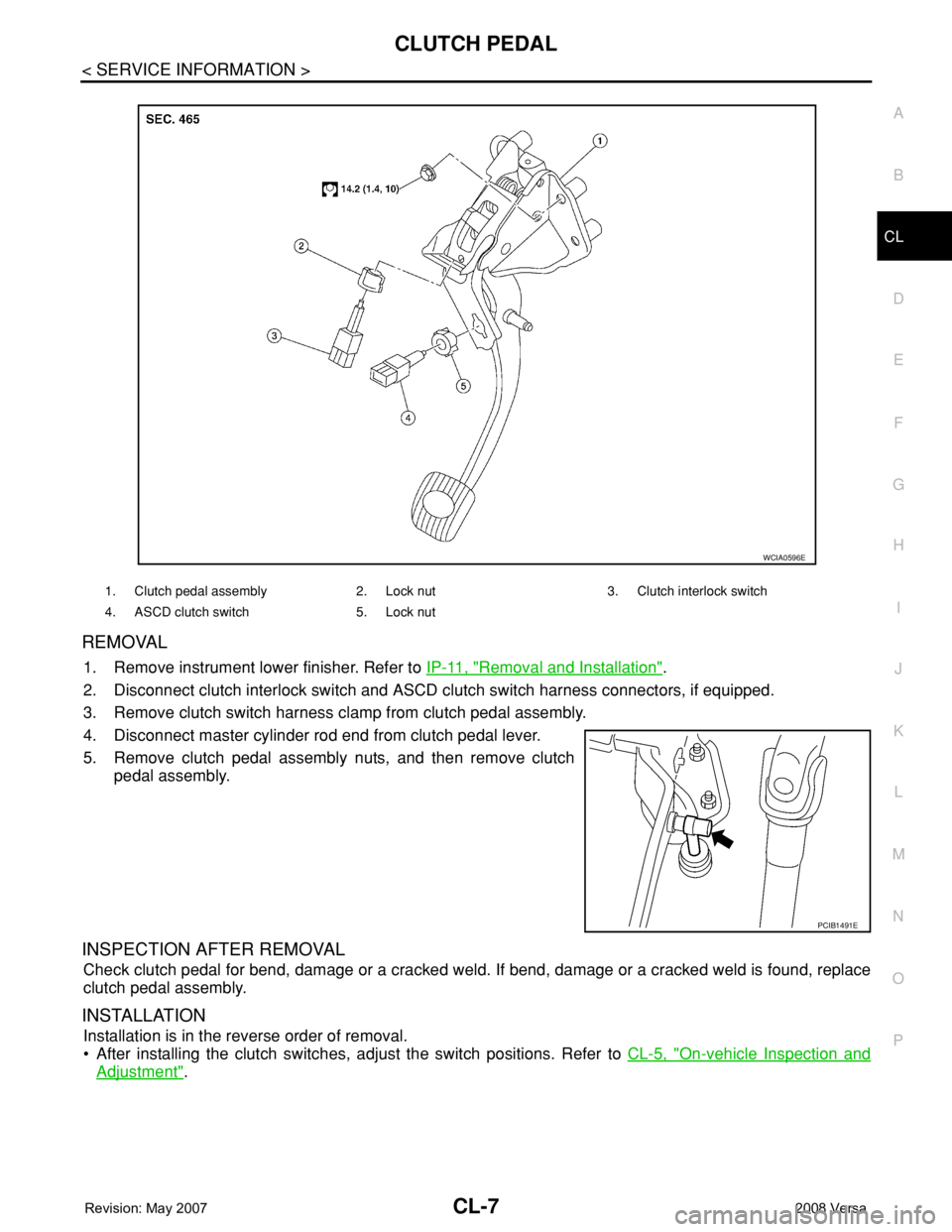
REMOVAL
1. Remove instrument lower finisher. Refer to IP-11, "Removal and Installation".
2. Disconnect clutch interlock switch and ASCD clutch switch harness connectors, if equipped.
3. Remove clutch switch harness clamp from clutch pedal assembly.
4. Disconnect master cylinder rod end from clutch pedal lever.
5. Remove clutch pedal assembly nuts, and then remove clutch
pedal assembly.
INSPECTION AFTER REMOVAL
Check clutch pedal for bend, damage or a cracked weld. If bend, damage or a cracked weld is found, replace
clutch pedal assembly.
INSTALLATION
Installation is in the reverse order of removal.
• After installing the clutch switches, adjust the switch positions. Refer to CL-5, "
On-vehicle Inspection and
Adjustment".
1. Clutch pedal assembly 2. Lock nut 3. Clutch interlock switch
4. ASCD clutch switch 5. Lock nut
WCIA0596E
PCIB1491E
Page 817 of 2771

CL-16
< SERVICE INFORMATION >
SERVICE DATA AND SPECIFICATIONS (SDS)
SERVICE DATA AND SPECIFICATIONS (SDS)
Clutch Control SystemINFOID:0000000001703124
Clutch PedalINFOID:0000000001703125
Clutch DiscINFOID:0000000001703126
Clutch CoverINFOID:0000000001703127
Type of clutch controlHydraulic
Clearance ″A″ between clutch pedal and ASCD switch threaded
end while clutch pedal is fully released (if equipped). 0.74 - 1.96 mm (0.0291 - 0.0772 in)
Clearance ″C″ between clutch pedal and clutch interlock switch
threaded end while clutch pedal is fully depressed.0.74 - 1.96 mm (0.0291 - 0.0772 in)
Model225
Facing size (outer dia. × inner dia. × thickness) 225 mm × 160 mm × 3.2 mm (8.86 in × 6.30 in × 0.126 in)
Thickness of disc assembly with load 7.2 - 7.6 mm (0.283 - 0.299 in) with 5,394 N (550 kg, 1,213 lb)
Runout limit/diameter of the area to be measured 1.0 mm (0.039 in) / 215 mm (8.46 in) dia.
Maximum spline backlash (at outer edge of disc) 1.0 mm (0.039 in)
Wear limit of facing (depth to the rivet head) 0.3 mm (0.012 in)
Set-load5,394 N (550 kg, 1,213 lb)
Diaphragm spring lever height 20 - 22 mm (0.79 - 0.87 in)
Uneven limit of diaphragm spring toe height 0.7 mm (0.028 in) or less
Page 819 of 2771
CO-2
< SERVICE INFORMATION >
PRECAUTIONS
SERVICE INFORMATION
PRECAUTIONS
Precaution for Supplemental Restraint System (SRS) "AIR BAG" and "SEAT BELT
PRE-TENSIONER"
INFOID:0000000001702522
The Supplemental Restraint System such as “AIR BAG” and “SEAT BELT PRE-TENSIONER”, used along
with a front seat belt, helps to reduce the risk or severity of injury to the driver and front passenger for certain
types of collision. This system includes seat belt switch inputs and dual stage front air bag modules. The SRS
system uses the seat belt switches to determine the front air bag deployment, and may only deploy one front
air bag, depending on the severity of a collision and whether the front occupants are belted or unbelted.
Information necessary to service the system safely is included in the SRS and SB section of this Service Man-
ual.
WARNING:
• To avoid rendering the SRS inoperative, which could increase the risk of personal injury or death in
the event of a collision which would result in air bag inflation, all maintenance must be performed by
an authorized NISSAN/INFINITI dealer.
• Improper maintenance, including incorrect removal and installation of the SRS, can lead to personal
injury caused by unintentional activation of the system. For removal of Spiral Cable and Air Bag
Module, see the SRS section.
• Do not use electrical test equipment on any circuit related to the SRS unless instructed to in this
Service Manual. SRS wiring harnesses can be identified by yellow and/or orange harnesses or har-
ness connectors.
Precaution Necessary for Steering Wheel Rotation After Battery Disconnect
INFOID:0000000001702523
NOTE:
• This Procedure is applied only to models with Intelligent Key system and NATS (NISSAN ANTI-THEFT SYS-
TEM).
• Remove and install all control units after disconnecting both battery cables with the ignition knob in the
″LOCK″ position.
• Always use CONSULT-III to perform self-diagnosis as a part of each function inspection after finishing work.
If DTC is detected, perform trouble diagnosis according to self-diagnostic results.
For models equipped with the Intelligent Key system and NATS, an electrically controlled steering lock mech-
anism is adopted on the key cylinder.
For this reason, if the battery is disconnected or if the battery is discharged, the steering wheel will lock and
steering wheel rotation will become impossible.
If steering wheel rotation is required when battery power is interrupted, follow the procedure below before
starting the repair operation.
OPERATION PROCEDURE
1. Connect both battery cables.
NOTE:
Supply power using jumper cables if battery is discharged.
2. Use the Intelligent Key or mechanical key to turn the ignition switch to the ″ACC″ position. At this time, the
steering lock will be released.
3. Disconnect both battery cables. The steering lock will remain released and the steering wheel can be
rotated.
4. Perform the necessary repair operation.
5. When the repair work is completed, return the ignition switch to the ″LOCK″ position before connecting
the battery cables. (At this time, the steering lock mechanism will engage.)
6. Perform a self-diagnosis check of all control units using CONSULT-III.
Precaution for Liquid GasketINFOID:0000000001702524
REMOVAL OF LIQUID GASKET SEALING
• After removing nuts and bolts, separate the mating surface, using Tool and remove old liquid gasket sealing.
Page 841 of 2771

CVT-2
Description ..............................................................60
CONSULT-III Reference Value in Data Monitor
Mode .......................................................................
60
On Board Diagnosis Logic ......................................60
Possible Cause .......................................................60
DTC Confirmation Procedure .................................60
Wiring Diagram - CVT - STSIG ...............................61
Diagnosis Procedure ..............................................62
DTC P0703 STOP LAMP SWITCH CIRCUIT ....63
Description ..............................................................63
CONSULT-III Reference Value in Data Monitor
Mode .......................................................................
63
On Board Diagnosis Logic ......................................63
Possible Cause .......................................................63
DTC Confirmation Procedure .................................63
Diagnosis Procedure ..............................................63
DTC P0705 PARK/NEUTRAL POSITION
SWITCH .............................................................
65
Description ..............................................................65
CONSULT-III Reference Value in Data Monitor
Mode .......................................................................
65
On Board Diagnosis Logic ......................................65
Possible Cause .......................................................65
DTC Confirmation Procedure .................................65
Wiring Diagram - CVT - PNP/SW ...........................67
Diagnosis Procedure ..............................................68
Component Inspection ............................................70
DTC P0710 CVT FLUID TEMPERATURE
SENSOR CIRCUIT .............................................
71
Description ..............................................................71
CONSULT-III Reference Value in Data Monitor
Mode .......................................................................
71
On Board Diagnosis Logic ......................................71
Possible Cause .......................................................71
DTC Confirmation Procedure .................................71
Wiring Diagram - CVT - FTS ...................................72
Diagnosis Procedure ..............................................73
Component Inspection ............................................74
DTC P0715 INPUT SPEED SENSOR CIR-
CUIT (PRI SPEED SENSOR) ............................
76
Description ..............................................................76
CONSULT-III Reference Value in Data Monitor
Mode .......................................................................
76
On Board Diagnosis Logic ......................................76
Possible Cause .......................................................76
DTC Confirmation Procedure .................................76
Wiring Diagram - CVT - PRSCVT ...........................77
Diagnosis Procedure ..............................................78
DTC P0720 VEHICLE SPEED SENSOR CVT
(SECONDARY SPEED SENSOR) .....................
80
Description ..............................................................80
CONSULT-III Reference Value in Data Monitor
Mode .......................................................................
80
On Board Diagnosis Logic ......................................80
Possible Cause .......................................................80
DTC Confirmation Procedure ..................................80
Wiring Diagram - CVT - SESCVT ...........................81
Diagnosis Procedure ...............................................82
DTC P0725 ENGINE SPEED SIGNAL ..............85
Description ..............................................................85
CONSULT-III Reference Value in Data Monitor
Mode .......................................................................
85
On Board Diagnosis Logic ......................................85
Possible Cause .......................................................85
DTC Confirmation Procedure ..................................85
Diagnosis Procedure ...............................................85
DTC P0730 BELT DAMAGE .............................87
Description ..............................................................87
CONSULT-III Reference Value in Data Monitor
Mode .......................................................................
87
On Board Diagnosis Logic ......................................87
Possible Cause .......................................................87
DTC Confirmation Procedure ..................................87
Diagnosis Procedure ...............................................87
DTC P0740 TORQUE CONVERTER CLUTCH
SOLENOID VALVE ...........................................
88
Description ..............................................................88
CONSULT-III Reference Value in Data Monitor
Mode .......................................................................
88
On Board Diagnosis Logic ......................................88
Possible Cause .......................................................88
DTC Confirmation Procedure ..................................88
Wiring Diagram - CVT - TCV ..................................89
Diagnosis Procedure ...............................................90
Component Inspection ............................................91
DTC P0744 A/T TCC S/V FUNCTION (LOCK-
UP) .....................................................................
93
Description ..............................................................93
CONSULT-III Reference Value in Data Monitor
Mode .......................................................................
93
On Board Diagnosis Logic ......................................93
Possible Cause .......................................................93
DTC Confirmation Procedure ..................................93
Diagnosis Procedure ...............................................93
DTC P0745 LINE PRESSURE SOLENOID
VALVE ...............................................................
95
Description ..............................................................95
CONSULT-III Reference Value in Data Monitor
Mode .......................................................................
95
On Board Diagnosis Logic ......................................95
Possible Cause .......................................................95
DTC Confirmation Procedure ..................................95
Wiring Diagram - CVT - LPSV ................................96
Diagnosis Procedure ...............................................97
Component Inspection ............................................98
DTC P0746 PRESSURE CONTROL SOLE-
NOID A PERFORMANCE (LINE PRESSURE
SOLENOID VALVE) .........................................
100
Description ............................................................100