2008 NISSAN TIIDA PN switch
[x] Cancel search: PN switchPage 881 of 2771
CVT-42
< SERVICE INFORMATION >
TROUBLE DIAGNOSIS
YES >> GO TO 2.
NO >> Stop “Road Test”. Mark the box on the CVT-30, "
How to Perform Trouble Diagnosis for Quick and
Accurate Repair" . Go to CVT-153, "Engine Cannot Be Started in "P" and "N" Position" .
2.CHECK STARTING THE ENGINE
1. Turn ignition switch ON.
2. Move selector lever to “D”, “L” or “R” position.
3. Turn ignition switch START.
Is engine started?
YES >> Stop “Road Test”. Mark the box on the CVT-30, "How to Perform Trouble Diagnosis for Quick and
Accurate Repair" . Go to CVT-153, "Engine Cannot Be Started in "P" and "N" Position" .
NO >> GO TO 3.
3.CHECK “P” POSITION FUNCTION
1. Move selector lever to “P” position.
2. Turn ignition switch OFF.
3. Release parking brake.
4. Push vehicle forward or backward.
5. Apply parking brake.
Does vehicle move when it is pushed forward or backward?
YES >> Mark the box CVT-153, "In "P" Position, Vehicle Moves Forward or Backward When Pushed" on
the CVT-30, "
How to Perform Trouble Diagnosis for Quick and Accurate Repair" . Continue “Road
Te s t ” .
NO >> GO TO 4.
4.CHECK “N” POSITION FUNCTION
1. Start engine.
2. Move selector lever to “N” position.
3. Release parking brake.
Does vehicle move forward or backward?
YES >> Mark the box CVT-154, "In "N" Position, Vehicle Moves" on the CVT-30, "How to Perform Trouble
Diagnosis for Quick and Accurate Repair" . Continue “Road Test”.
NO >> GO TO 5.
5.CHECK SHIFT SHOCK
1. Apply foot brake.
2. Move selector lever to “R” position.
Is there large shock when changing from
“N” to “R” position?
YES >> Mark the box CVT-154, "Large Shock "N" → "R" Position" on the CVT-30, "How to Perform Trou-
ble Diagnosis for Quick and Accurate Repair" . Continue “Road Test”.
NO >> GO TO 6.
6.CHECK “R” POSITION FUNCTION
Release foot brake for several seconds.
Does vehicle creep backward when foot brake is released?
YES >> GO TO 7.
NO >> Mark the box CVT-155, "
Vehicle Does Not Creep Backward in "R" Position" on the CVT-30, "How
to Perform Trouble Diagnosis for Quick and Accurate Repair" . Continue “Road Test”.
7.CHECK “D”, “L” POSITIONS FUNCTION
Move selector lever to “D” and “L” positions and check if vehicle creeps forward.
Does vehicle creep forward in all positions?
YES >> Go to CVT-43, "Cruise Test" .
NO >> Stop “Road Test”. Mark the box on the CVT-30, "
How to Perform Trouble Diagnosis for Quick and
Accurate Repair" . Go to CVT-156, "Vehicle Does Not Creep Forward in "D" or "L" Position" .
Page 882 of 2771
TROUBLE DIAGNOSIS
CVT-43
< SERVICE INFORMATION >
D
E
F
G
H
I
J
K
L
MA
B
CVT
N
O
P
Cruise TestINFOID:0000000001703460
1.CHECK VEHICLE SPEED WHEN SHIFTING GEARS — PART 1
1. Drive vehicle for approximately 10 minutes to warm engine oil and CVT fluid up to operating temperature.
2. Park vehicle on flat surface.
3. Move selector lever to “P” position.
4. Start engine.
5. Move selector lever to “L” position.
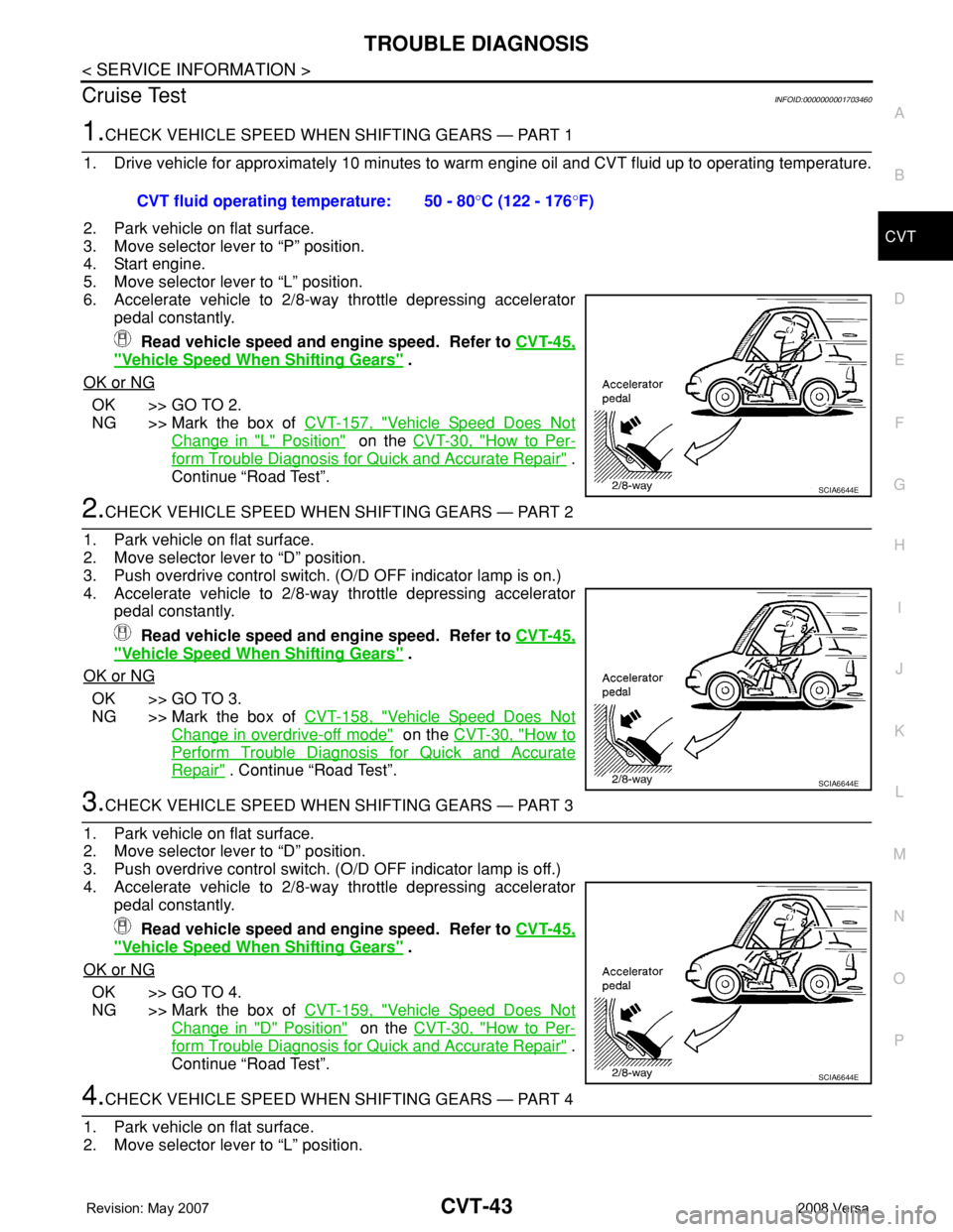
6. Accelerate vehicle to 2/8-way throttle depressing accelerator
pedal constantly.
Read vehicle speed and engine speed. Refer to CVT-45,
"Vehicle Speed When Shifting Gears" .
OK or NG
OK >> GO TO 2.
NG >> Mark the box of CVT-157, "
Vehicle Speed Does Not
Change in "L" Position" on the CVT-30, "How to Per-
form Trouble Diagnosis for Quick and Accurate Repair" .
Continue “Road Test”.
2.CHECK VEHICLE SPEED WHEN SHIFTING GEARS — PART 2
1. Park vehicle on flat surface.
2. Move selector lever to “D” position.
3. Push overdrive control switch. (O/D OFF indicator lamp is on.)
4. Accelerate vehicle to 2/8-way throttle depressing accelerator
pedal constantly.
Read vehicle speed and engine speed. Refer to CVT-45,
"Vehicle Speed When Shifting Gears" .
OK or NG
OK >> GO TO 3.
NG >> Mark the box of CVT-158, "
Vehicle Speed Does Not
Change in overdrive-off mode" on the CVT-30, "How to
Perform Trouble Diagnosis for Quick and Accurate
Repair" . Continue “Road Test”.
3.CHECK VEHICLE SPEED WHEN SHIFTING GEARS — PART 3
1. Park vehicle on flat surface.
2. Move selector lever to “D” position.
3. Push overdrive control switch. (O/D OFF indicator lamp is off.)
4. Accelerate vehicle to 2/8-way throttle depressing accelerator
pedal constantly.
Read vehicle speed and engine speed. Refer to CVT-45,
"Vehicle Speed When Shifting Gears" .
OK or NG
OK >> GO TO 4.
NG >> Mark the box of CVT-159, "
Vehicle Speed Does Not
Change in "D" Position" on the CVT-30, "How to Per-
form Trouble Diagnosis for Quick and Accurate Repair" .
Continue “Road Test”.
4.CHECK VEHICLE SPEED WHEN SHIFTING GEARS — PART 4
1. Park vehicle on flat surface.
2. Move selector lever to “L” position. CVT fluid operating temperature: 50 - 80°C (122 - 176°F)
SCIA6644E
SCIA6644E
SCIA6644E
Page 883 of 2771
CVT-44
< SERVICE INFORMATION >
TROUBLE DIAGNOSIS
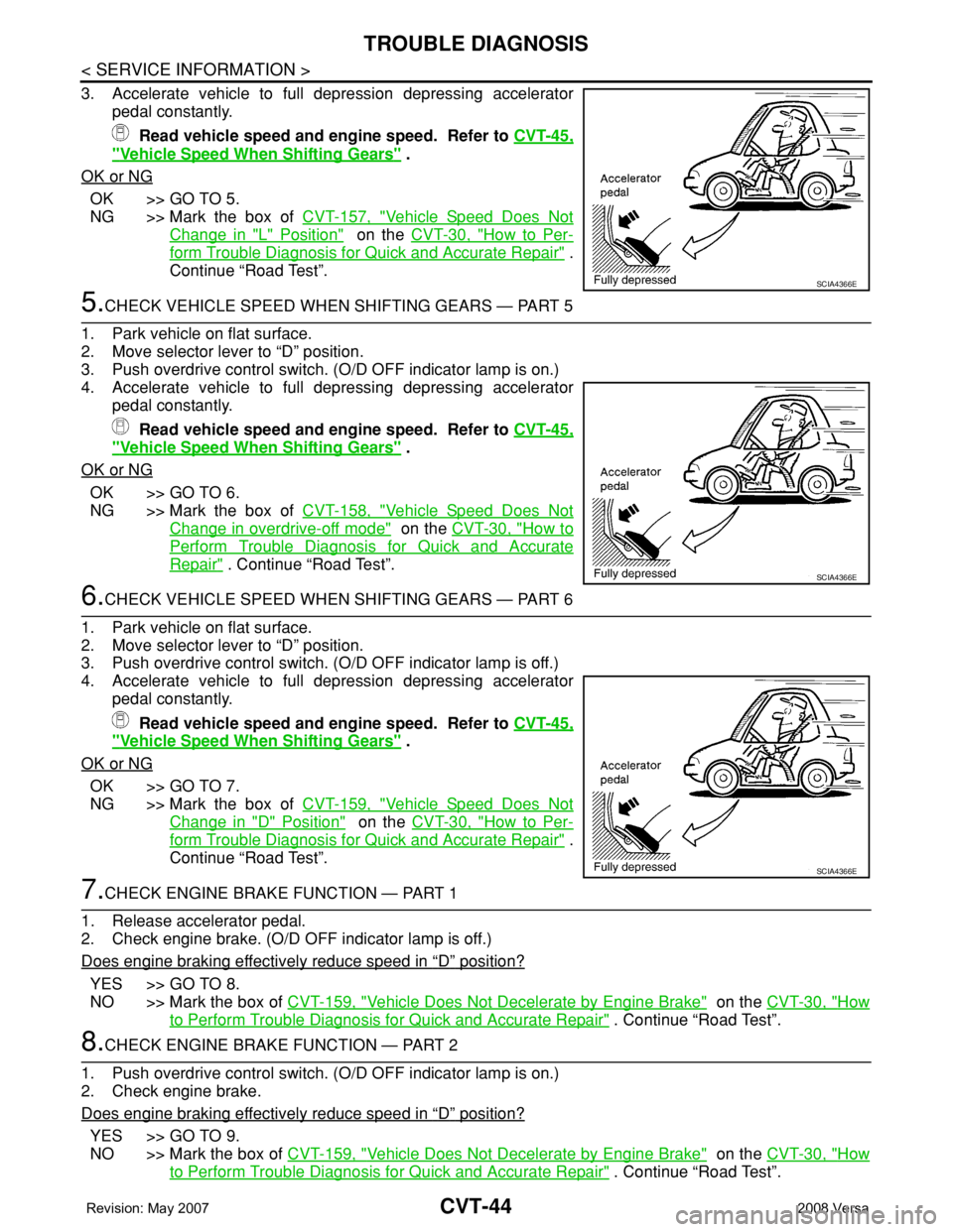
3. Accelerate vehicle to full depression depressing accelerator
pedal constantly.
Read vehicle speed and engine speed. Refer to CVT-45,
"Vehicle Speed When Shifting Gears" .
OK or NG
OK >> GO TO 5.
NG >> Mark the box of CVT-157, "
Vehicle Speed Does Not
Change in "L" Position" on the CVT-30, "How to Per-
form Trouble Diagnosis for Quick and Accurate Repair" .
Continue “Road Test”.
5.CHECK VEHICLE SPEED WHEN SHIFTING GEARS — PART 5
1. Park vehicle on flat surface.
2. Move selector lever to “D” position.
3. Push overdrive control switch. (O/D OFF indicator lamp is on.)
4. Accelerate vehicle to full depressing depressing accelerator
pedal constantly.
Read vehicle speed and engine speed. Refer to CVT-45,
"Vehicle Speed When Shifting Gears" .
OK or NG
OK >> GO TO 6.
NG >> Mark the box of CVT-158, "
Vehicle Speed Does Not
Change in overdrive-off mode" on the CVT-30, "How to
Perform Trouble Diagnosis for Quick and Accurate
Repair" . Continue “Road Test”.
6.CHECK VEHICLE SPEED WHEN SHIFTING GEARS — PART 6
1. Park vehicle on flat surface.
2. Move selector lever to “D” position.
3. Push overdrive control switch. (O/D OFF indicator lamp is off.)
4. Accelerate vehicle to full depression depressing accelerator
pedal constantly.
Read vehicle speed and engine speed. Refer to CVT-45,
"Vehicle Speed When Shifting Gears" .
OK or NG
OK >> GO TO 7.
NG >> Mark the box of CVT-159, "
Vehicle Speed Does Not
Change in "D" Position" on the CVT-30, "How to Per-
form Trouble Diagnosis for Quick and Accurate Repair" .
Continue “Road Test”.
7.CHECK ENGINE BRAKE FUNCTION — PART 1
1. Release accelerator pedal.
2. Check engine brake. (O/D OFF indicator lamp is off.)
Does engine braking effectively reduce speed in
“D” position?
YES >> GO TO 8.
NO >> Mark the box of CVT-159, "
Vehicle Does Not Decelerate by Engine Brake" on the CVT-30, "How
to Perform Trouble Diagnosis for Quick and Accurate Repair" . Continue “Road Test”.
8.CHECK ENGINE BRAKE FUNCTION — PART 2
1. Push overdrive control switch. (O/D OFF indicator lamp is on.)
2. Check engine brake.
Does engine braking effectively reduce speed in
“D” position?
YES >> GO TO 9.
NO >> Mark the box of CVT-159, "
Vehicle Does Not Decelerate by Engine Brake" on the CVT-30, "How
to Perform Trouble Diagnosis for Quick and Accurate Repair" . Continue “Road Test”.
SCIA4366E
SCIA4366E
SCIA4366E
Page 885 of 2771

CVT-46
< SERVICE INFORMATION >
TROUBLE DIAGNOSIS
4BRLock-up select
solenoid valveSelector lever in “P” and “N” positions Battery voltage
Wait at least for 5 seconds with the selector lever in
“R”, “D” and “L” positions0 V
5 L CAN-H — —
6 P CAN-L — —
8VBack-up lamp
relaySelector lever in “R” position. 0 V
Selector lever in other positions. Battery voltage
10 R Power supply— Battery voltage
—0 V
11 L Step motor A Within 2 seconds after ignition switch ON, the time measurement by using
the pulse width measurement function (Hi level) of CONSULT-III.*1
*1: A circuit tester cannot be used to test this item.30.0 msec
12 Y Step motor B10.0 msec
13 G ROM assembly — —
14 Y ROM assembly — —
15 G ROM assembly — —
19 R Power supply— Battery voltage
—0 V
20 W Step motor C Within 2 seconds after ignition switch ON, the time measurement by using
the pulse width measurement function (Hi level) of CONSULT-III.*1
*1: A circuit tester cannot be used to test this item.30.0 msec
21 P Step motor D10.0 msec
24 BR Starter relaySelector lever in “N” and “P”positions. Battery voltage
Selector lever in other positions. 0 V
25 B Ground Always 0 V
27 GR PNP switch 1Selector lever in “R”, “N” and “D” positions. 0 V
Selector lever in “P” and “L” positions. Battery voltage
28 YPower supply
(memory back-
up)Always Battery voltage
29 ROutput speed
sensor (Second-
ary speed sen-
sor)When driving [“D” position, 20 km/h (12 MPH)]. 570 Hz
31 LG K-LINE — — Te r m i n a lWire
colorItem Condition Data (Approx.)
Page 886 of 2771
TROUBLE DIAGNOSIS
CVT-47
< SERVICE INFORMATION >
D
E
F
G
H
I
J
K
L
MA
B
CVT
N
O
P
CONSULT-III Function (TRANSMISSION)INFOID:0000000001703463
CONSULT-III can display each diagnostic item using the diagnostic test modes shown below.
FUNCTION
32 YPNP switch 3
(monitor)Selector lever in “D” and “L” positions. 0 V
Selector lever in “P”, “R” and “N” positions.8.0 V - Battery
voltage
34 SB PNP switch 2Selector lever in “N”, “D” and “L” positions. 0 V
Selector lever in “P” and “R” positions.10.0 V - Battery
voltage
35 W PNP switch 3Selector lever in “D” and “L” positions. 0 V
Selector lever in “P”, “R” and “N” positions.8.0 V - Battery
voltage
36 W PNP switch 4Selector lever in “R” and “D” positions. 0 V
Selector lever in “P”, “N” and “L” positions.10.0 V - Battery
voltage
37 LTransmission
fluid pressure
sensor A (Sec-
ondary pressure
sensor)and “N” position idle 1.0 V
38 VInput speed sen-
sor (Primary
speed sensor)When driving [“L” position, 20 km/h (12 MPH)]. 1000 Hz
41 GTransmission
fluid pressure
sensor B (Prima-
ry pressure sen-
sor)and “N” position idle 0.7 V
42 LG Sensor ground Always 0 V
46 O Sensor power— 5.0 V
— 0 V
47 GCVT fluid tem-
perature sensor When CVT fluid temperature is 20°C (68°F) 2.0 V
When CVT fluid temperature is 80°C (176°F) 1.0 V
48 B Ground Always 0 V Te r m i n a lWire
colorItem Condition Data (Approx.)
Diagnostic test mode Function
Work supportThis mode enables a technician to adjust some devices faster and more accurately by following the in-
dications on CONSULT-III.
Self-diagnostic results Self-diagnostic results can be read and erased quickly.
Data monitor Input/Output data in the TCM can be read.
Page 887 of 2771

CVT-48
< SERVICE INFORMATION >
TROUBLE DIAGNOSIS
CONSULT-III REFERENCE VALUE
CAN diagnostic support mon-
itorThe results of transmit/receive diagnosis of CAN communication can be read.
CALIB data Characteristic information for TCM and CVT assembly can be read.
Function test Performed by CONSULT-III instead of a technician to determine whether each system is “OK” or “NG”.
ECU part number TCM part number can be read.Diagnostic test mode Function
Item name Condition Display value (Approx.)
VSP SENSOR
During drivingApproximately matches the speedometer
reading.
ESTM VSP SIG*
PRI SPEED SEN During driving (lock-up ON) Approximately matches the engine speed.
ENG SPEED SIG Engine running Closely matches the tachometer reading.
SEC HYDR SEN “N” position idle 1.0 V
PRI HYDR SEN “N” position idle 0.7 V
ATF TEMP SENWhen CVT fluid temperature is 20°C (68°F). 2.0 V
When CVT fluid temperature is 80°C (176°F). 1.0 V
VIGN SEN Ignition switch: ON Battery voltage
VEHICLE SPEED During drivingApproximately matches the speedometer
reading.
PRI SPEED During driving (lock-up ON) Approximately matches the engine speed.
SEC SPEED During driving50 X Approximately matches the speedom-
eter reading.
ENG SPEED Engine running Closely matches the tachometer reading.
GEAR RATIO During driving 2.56 - 0.43
ACC PEDAL OPENReleased accelerator pedal - Fully depressed
accelerator pedal0.0/8 - 8.0/8
SEC PRESS “N” position idle 0.8 MPa
PRI PRESS “N” position idle 0.4 MPa
STM STEP During driving−20 step - 180 step
ISOLT1Lock-up OFF 0.0 A
Lock-up ON 0.7 A
ISOLT2Release your foot from the accelerator pedal. 0.8 A
Press the accelerator pedal all the way down. 0.0 A
ISOLT3Secondary pressure low - Secondary pressure
high.0.8 - 0.0 A
SOLMON1Lock-up OFF 0.0 A
Lock-up ON 0.7 A
SOLMON2“N” position idle 0.8 A
When stalled 0.3 - 0.6 A
SOLMON3“N” position idle 0.6 - 0.7 A
When stalled 0.4 - 0.6 A
INH SW3MSelector lever in “D” and “L” positions ON
Selector lever in “P”, “R” and “N” positions OFF
INH SW4Selector lever in “R” and “D” positions ON
Selector lever in “P”, “N” and “L” positions OFF
Page 888 of 2771

TROUBLE DIAGNOSIS
CVT-49
< SERVICE INFORMATION >
D
E
F
G
H
I
J
K
L
MA
B
CVT
N
O
P
*: Models without ABS does not indicate.
WORK SUPPORT MODE
Display Item List
INH SW3Selector lever in “D” and “L” positions ON
Selector lever in “P”, “R” and “N” positions OFF
INH SW2Selector lever in “N”, “D” and “L” positions ON
Selector lever in “P” and “R” positions OFF
INH SW1Selector lever in “R”, “N” and “D” positions ON
Selector lever in “P” and “L” positions OFF
BRAKE SWDepressed brake pedal ON
Released brake pedal OFF
FULL SWFully depressed accelerator pedal ON
Released accelerator pedal OFF
IDLE SWReleased accelerator pedal ON
Fully depressed accelerator pedal OFF
SPORT MODE SWWhile pushing overdrive cancel switch ON
Other conditions OFF
INDDRNGSelector lever in “D” position ON
Selector lever in other positions OFF
INDLRNGSelector lever in “L” position ON
Selector lever in other positions OFF
INDNRNGSelector lever in “N” position ON
Selector lever in other positions OFF
INDRRNGSelector lever in “R” position ON
Selector lever in other positions OFF
INDPRNGSelector lever in “P” position ON
Selector lever in other positions OFF
SMCOIL D
During driving Changes ON ⇔ OFF. SMCOIL C
SMCOIL B
SMCOIL A
LUSEL SOL OUTSelector lever in “P” and “N” positions ON
Wait at least for 5 seconds with the selector lever
in “R”, “D” and “L” positionsOFF
STRTR RLY OUTSelector lever in “P” and “N” positions ON
Selector lever in other positions OFF
STRTR RLY MONSelector lever in “P” and “N” positions ON
Selector lever in other positions OFF
RANGESelector lever in “N” or “P” position. N·P
Selector lever in “R” position. R
Selector lever in “D” position. D
Selector lever in “L” position. L Item name Condition Display value (Approx.)
Page 889 of 2771
CVT-50
< SERVICE INFORMATION >
TROUBLE DIAGNOSIS
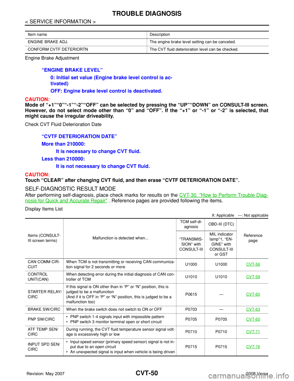
Engine Brake Adjustment
CAUTION:
Mode of “+1”“0”“-1”“-2”“OFF” can be selected by pressing the “UP”“DOWN” on CONSULT-III screen.
However, do not select mode other than “0” and “OFF”. If the “+1” or “-1” or “-2” is selected, that
might cause the irregular driveability.
Check CVT Fluid Deterioration Date
CAUTION:
Touch “CLEAR” after changing CVT fluid, and then erase “CVTF DETERIORATION DATE”.
SELF-DIAGNOSTIC RESULT MODE
After performing self-diagnosis, place check marks for results on the CVT-30, "How to Perform Trouble Diag-
nosis for Quick and Accurate Repair" . Reference pages are provided following the items.
Display Items List
X: Applicable —: Not applicable
Item name Description
ENGINE BRAKE ADJ. The engine brake level setting can be canceled.
CONFORM CVTF DETERIORTN The CVT fluid deterioration level can be checked.
“ENGINE BRAKE LEVEL”
0: Initial set value (Engine brake level control is ac-
tivated)
OFF: Engine brake level control is deactivated.
“CVTF DETERIORATION DATE”
More than 210000:
It is necessary to change CVT fluid.
Less than 210000:
It is not necessary to change CVT fluid.
Items (CONSULT-
III screen terms)Malfunction is detected when...TCM self-di-
agnosisOBD-III (DTC)
Reference
page “TRANSMIS-
SION” with
CONSULT-IIIMIL indicator
lamp*1, “EN-
GINE” with
CONSULT-III
or GST
CAN COMM CIR-
CUITWhen TCM is not transmitting or receiving CAN communica-
tion signal for 2 seconds or moreU1000 U1000CVT-56
CONTROL
UNIT(CAN)When detecting error during the initial diagnosis of CAN con-
troller of TCMU1010 U1010CVT-59
STARTER RELAY/
CIRCIf this signal is ON other than in “P” or “N” position, this is
judged to be a malfunction
(And if it is OFF in “P” or “N” position, this is judged to be a
malfunction too)P0615 —CVT-60
BRAKE SW/CIRC When the brake switch does not switch to ON or OFF P0703 —CVT-63
PNP SW/CIRC• PNP switch 1-4 signals input with impossible pattern
• PNP switch 3 monitor terminal open or short circuitP0705 P0705CVT-65
ATF TEMP SEN/
CIRCDuring running, the CVT fluid temperature sensor signal volt-
age is excessively high or lowP0710 P0710CVT-71
INPUT SPD SEN/
CIRC• Input speed sensor (primary speed sensor) signal is not in-
put due to an open circuit
• An unexpected signal is input when vehicle is being drivenP0715 P0715CVT-76