Page 503 of 2771
REMOTE KEYLESS ENTRY SYSTEM
BL-69
< SERVICE INFORMATION >
C
D
E
F
G
H
J
K
L
MA
B
BL
N
O
P
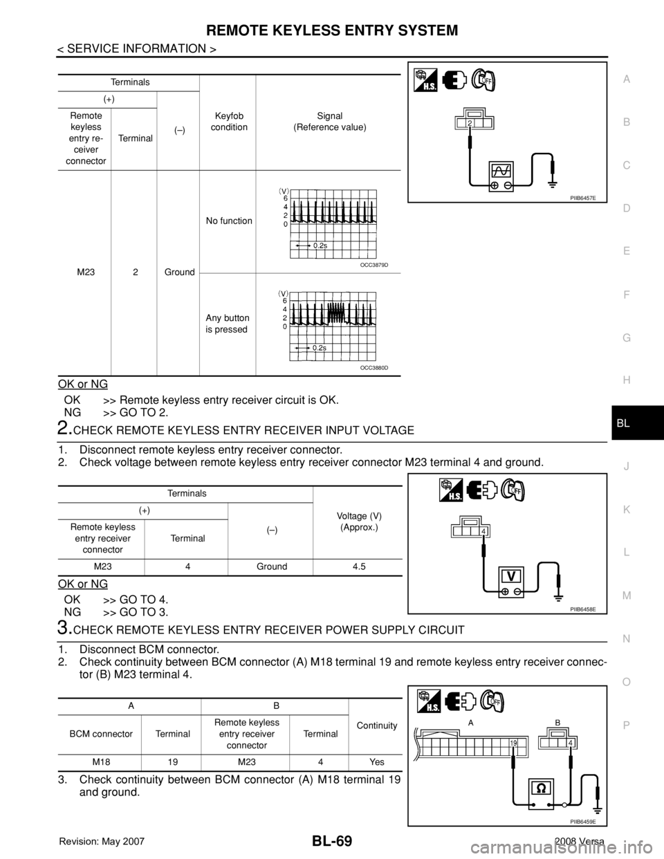
OK or NG
OK >> Remote keyless entry receiver circuit is OK.
NG >> GO TO 2.
2.CHECK REMOTE KEYLESS ENTRY RECEIVER INPUT VOLTAGE
1. Disconnect remote keyless entry receiver connector.
2. Check voltage between remote keyless entry receiver connector M23 terminal 4 and ground.
OK or NG
OK >> GO TO 4.
NG >> GO TO 3.
3.CHECK REMOTE KEYLESS ENTRY RECEIVER POWER SUPPLY CIRCUIT
1. Disconnect BCM connector.
2. Check continuity between BCM connector (A) M18 terminal 19 and remote keyless entry receiver connec-
tor (B) M23 terminal 4.
3. Check continuity between BCM connector (A) M18 terminal 19
and ground.
Te r m i n a l s
Keyfob
conditionSignal
(Reference value) (+)
(–) Remote
keyless
entry re-
ceiver
connectorTe r m i n a l
M23 2 GroundNo function
Any button
is pressed
PIIB6457E
OCC3879D
OCC3880D
Te r m i n a l s
Voltage (V)
(Approx.) (+)
(–) Remote keyless
entry receiver
connectorTe r m i n a l
M23 4 Ground 4.5
PIIB6458E
AB
Continuity
BCM connector TerminalRemote keyless
entry receiver
connectorTe r m i n a l
M18 19 M23 4 Yes
PIIB6459E
Page 504 of 2771
BL-70
< SERVICE INFORMATION >
REMOTE KEYLESS ENTRY SYSTEM
OK or NG
OK >> Replace BCM. Refer to BCS-18, "Removal and Installation of BCM" .
NG >> Repair or replace the harness.
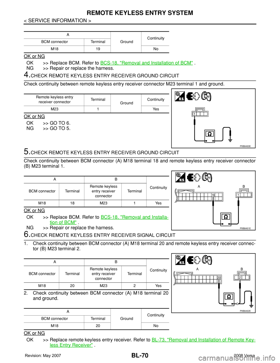
4.CHECK REMOTE KEYLESS ENTRY RECEIVER GROUND CIRCUIT
Check continuity between remote keyless entry receiver connector M23 terminal 1 and ground.
OK or NG
OK >> GO TO 6.
NG >> GO TO 5.
5.CHECK REMOTE KEYLESS ENTRY RECEIVER GROUND CIRCUIT
Check continuity between BCM connector (A) M18 terminal 18 and remote keyless entry receiver connector
(B) M23 terminal 1.
OK or NG
OK >> Replace BCM. Refer to BCS-18, "Removal and Installa-
tion of BCM" .
NG >> Repair or replace the harness.
6.CHECK REMOTE KEYLESS ENTRY RECEIVER SIGNAL CIRCUIT
1. Check continuity between BCM connector (A) M18 terminal 20 and remote keyless entry receiver connec-
tor (B) M23 terminal 2.
2. Check continuity between BCM connector (A) M18 terminal 20
and ground.
OK or NG
OK >> Replace remote keyless entry receiver. Refer to BL-73, "Removal and Installation of Remote Key-
less Entry Receiver" .
A
GroundContinuity
BCM connector Terminal
M18 19 No
Remote keyless entry
receiver connectorTe r m i n a l
GroundContinuity
M23 1 Yes
PIIB6460E
AB
Continuity
BCM connector TerminalRemote keyless
entry receiver
connectorTe r m i n a l
M18 18 M23 1 Yes
PIIB6461E
AB
Continuity
BCM connector TerminalRemote keyless
entry receiver
connectorTe r m i n a l
M18 20 M23 2 Yes
A
GroundContinuity
BCM connector Terminal
M18 20 No
PIIB6462E
Page 507 of 2771
REMOTE KEYLESS ENTRY SYSTEM
BL-73
< SERVICE INFORMATION >
C
D
E
F
G
H
J
K
L
MA
B
BL
N
O
P
To erase all ID codes in memory, register one ID code (keyfob) five times. After all ID codes are erased, the
ID codes of all remaining and/or new keyfobs must be re-registered.
• When registering an additional keyfob, the existing ID codes in memory may or may not be erased. If five ID
codes are stored in memory, when an additional code is registered, only the oldest code is erased. If less
than five ID codes are stored in memory, when an additional ID code is registered, the new ID code is added
and no ID codes are erased.
• If you need to activate more than two additional new keyfobs, repeat the procedure “Additional ID code
entry” for each new keyfob.
• Entry of maximum five ID codes is allowed. When more than five ID codes are entered, the oldest ID code
will be erased.
• Even if same ID code that is already in the memory is input, the same ID code can be entered. The code is
counted as an additional code.
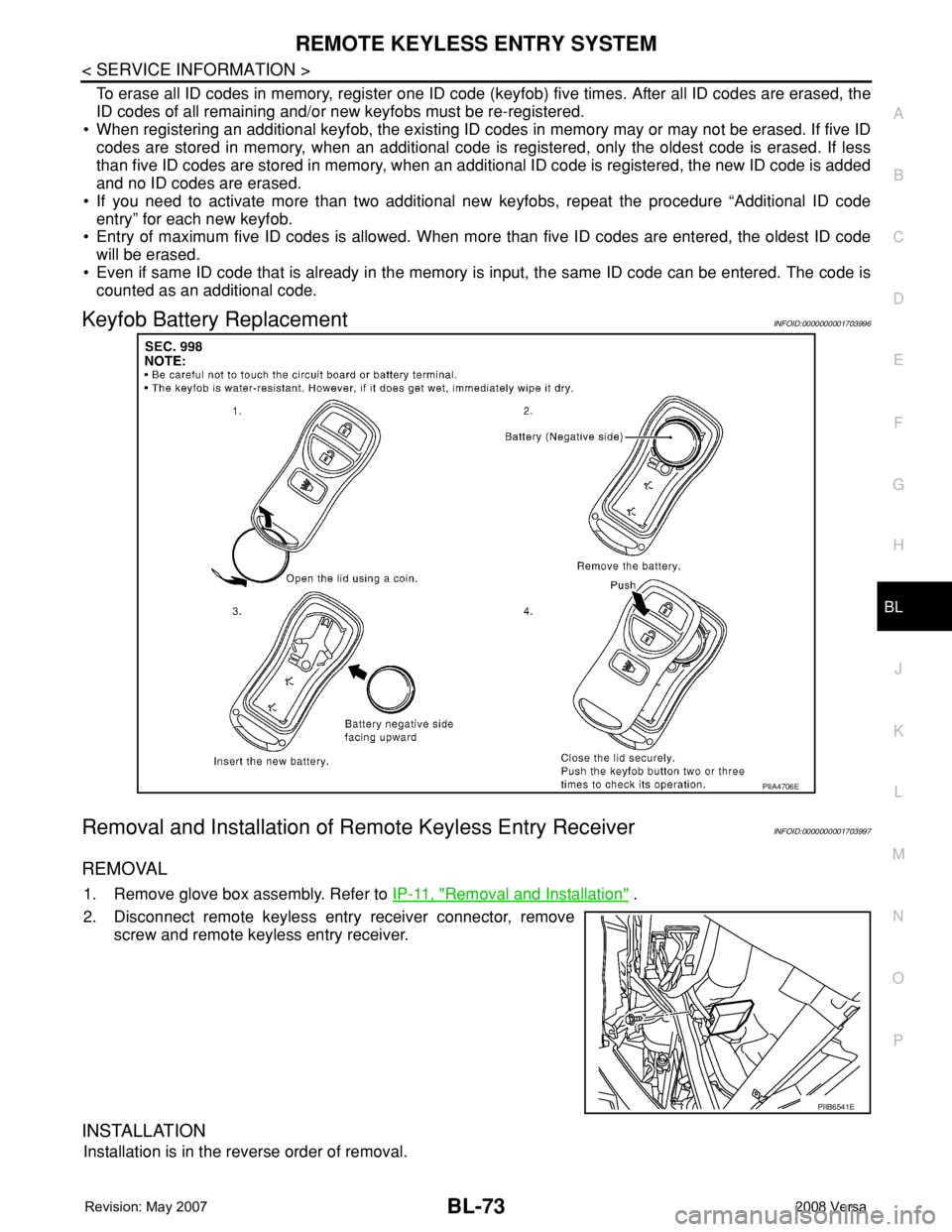
Keyfob Battery ReplacementINFOID:0000000001703996
Removal and Installation of Remote Keyless Entry ReceiverINFOID:0000000001703997
REMOVAL
1. Remove glove box assembly. Refer to IP-11, "Removal and Installation" .
2. Disconnect remote keyless entry receiver connector, remove
screw and remote keyless entry receiver.
INSTALLATION
Installation is in the reverse order of removal.
PIIA4706E
PIIB6541E
Page 508 of 2771
BL-74
< SERVICE INFORMATION >
INTELLIGENT KEY SYSTEM
INTELLIGENT KEY SYSTEM
Component Parts and Harness Connector LocationINFOID:0000000001703998
LIIA2916E
Page 530 of 2771
BL-96
< SERVICE INFORMATION >
INTELLIGENT KEY SYSTEM
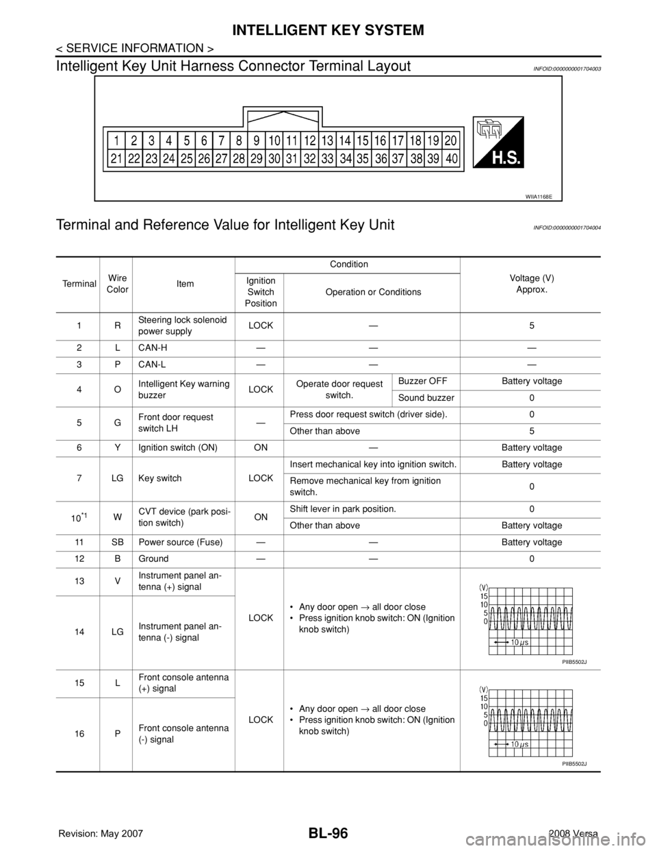
Intelligent Key Unit Harness Connector Terminal Layout
INFOID:0000000001704003
Terminal and Reference Value for Intelligent Key UnitINFOID:0000000001704004
WIIA1168E
Te r m i n a lWire
ColorItemCondition
Voltage (V)
Approx. Ignition
Switch
PositionOperation or Conditions
1RSteering lock solenoid
power supplyLOCK — 5
2 L CAN-H — — —
3 P CAN-L — — —
4OIntelligent Key warning
buzzerLOCKOperate door request
switch.Buzzer OFF Battery voltage
Sound buzzer 0
5GFront door request
switch LH—Press door request switch (driver side). 0
Other than above 5
6 Y Ignition switch (ON) ON — Battery voltage
7 LG Key switch LOCKInsert mechanical key into ignition switch. Battery voltage
Remove mechanical key from ignition
switch.0
10
*1WCVT device (park posi-
tion switch)ONShift lever in park position. 0
Other than above Battery voltage
11 SB Power source (Fuse) — — Battery voltage
12 B Ground — — 0
13 VInstrument panel an-
tenna (+) signal
LOCK• Any door open → all door close
• Press ignition knob switch: ON (Ignition
knob switch)
14 LGInstrument panel an-
tenna (-) signal
15 LFront console antenna
(+) signal
LOCK• Any door open → all door close
• Press ignition knob switch: ON (Ignition
knob switch)
16 PFront console antenna
(-) signal
PIIB5502J
PIIB5502J
Page 532 of 2771
BL-98
< SERVICE INFORMATION >
INTELLIGENT KEY SYSTEM
*1: With continuously variable transmission (CVT).
*2: With manual transmission (M/T).
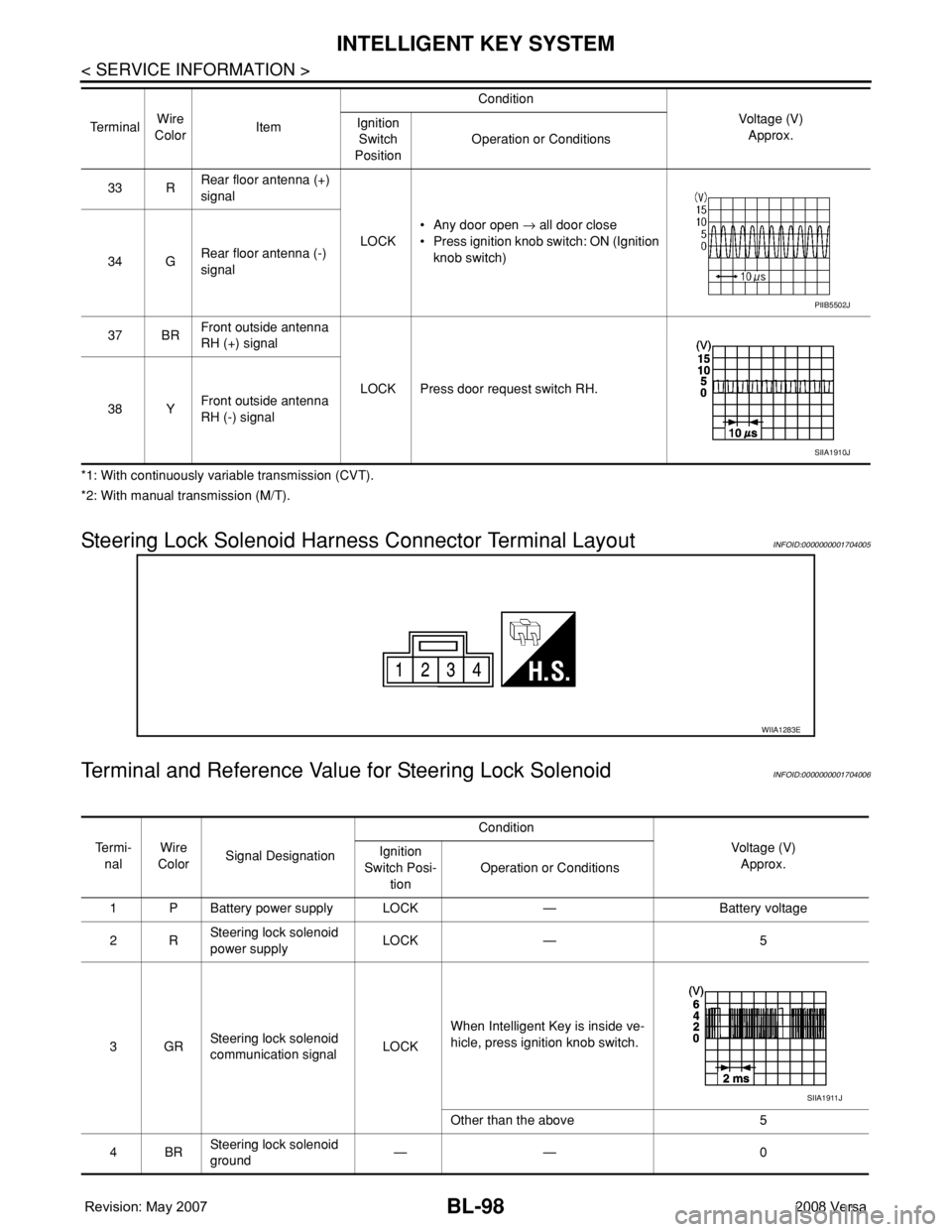
Steering Lock Solenoid Harness Connector Terminal LayoutINFOID:0000000001704005
Terminal and Reference Value for Steering Lock SolenoidINFOID:0000000001704006
33 RRear floor antenna (+)
signal
LOCK• Any door open → all door close
• Press ignition knob switch: ON (Ignition
knob switch)
34 GRear floor antenna (-)
signal
37 BRFront outside antenna
RH (+) signal
LOCK Press door request switch RH.
38 YFront outside antenna
RH (-) signal Te r m i n a lWire
ColorItemCondition
Voltage (V)
Approx. Ignition
Switch
PositionOperation or Conditions
PIIB5502J
SIIA1910J
WIIA1283E
Te r m i -
nalWire
ColorSignal DesignationCondition
Voltage (V)
Approx. Ignition
Switch Posi-
tionOperation or Conditions
1 P Battery power supply LOCK — Battery voltage
2RSteering lock solenoid
power supplyLOCK — 5
3GRSteering lock solenoid
communication signalLOCKWhen Intelligent Key is inside ve-
hicle, press ignition knob switch.
Other than the above 5
4BRSteering lock solenoid
ground—— 0
SIIA1911J
Page 544 of 2771
BL-110
< SERVICE INFORMATION >
INTELLIGENT KEY SYSTEM
With CONSULT-III
• Connect CONSULT-III, and turn ignition switch ON.
• Touch “INTELLIGENT KEY” on “SELECT SYSTEM” screen.
• Touch “SELF-DIAG RESULTS” on “SELECT DIAG MODE” screen.
• Check display content in self-diagnostic results.
OK or NG
NO DTC IS DETECTED>> INSPECTION END
CAN COMM [U1000]>> After printing “SELF-DIAGNOSIS RESULTS”, go to “CAN SYSTEM”. Refer to LAN-
15, "Trouble Diagnosis Flow Chart".
CAN COMM2 [U1010]>> Replace Intelligent Key unit.
Power Supply and Ground Circuit InspectionINFOID:0000000001704014
1.CHECK POWER SUPPLY CIRCUIT
1. Turn ignition switch OFF.
2. Disconnect Intelligent Key unit connector.
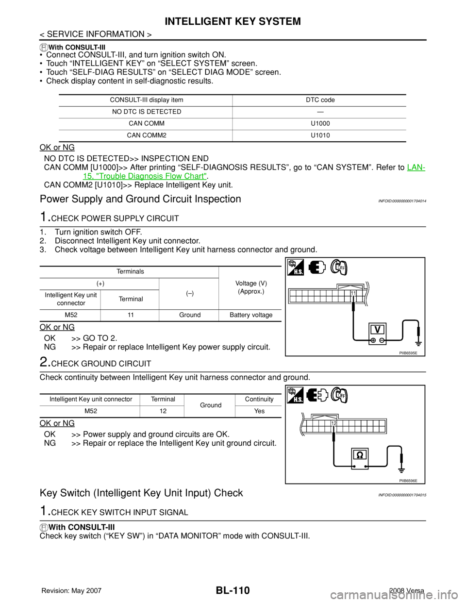
3. Check voltage between Intelligent Key unit harness connector and ground.
OK or NG
OK >> GO TO 2.
NG >> Repair or replace Intelligent Key power supply circuit.
2.CHECK GROUND CIRCUIT
Check continuity between Intelligent Key unit harness connector and ground.
OK or NG
OK >> Power supply and ground circuits are OK.
NG >> Repair or replace the Intelligent Key unit ground circuit.
Key Switch (Intelligent Key Unit Input) CheckINFOID:0000000001704015
1.CHECK KEY SWITCH INPUT SIGNAL
With CONSULT-III
Check key switch (“KEY SW”) in “DATA MONITOR” mode with CONSULT-III.
CONSULT-III display item DTC code
NO DTC IS DETECTED —
CAN COMM U1000
CAN COMM2 U1010
Te r m i n a l s
Voltage (V)
(Approx.) (+)
(–)
Intelligent Key unit
connectorTe r m i n a l
M52 11 Ground Battery voltage
PIIB6595E
Intelligent Key unit connector Terminal
GroundContinuity
M52 12 Yes
PIIB6596E
Page 545 of 2771
INTELLIGENT KEY SYSTEM
BL-111
< SERVICE INFORMATION >
C
D
E
F
G
H
J
K
L
MA
B
BL
N
O
P
Without CONSULT-III
1. Turn ignition switch OFF.
2. Disconnect Intelligent Key unit connector.
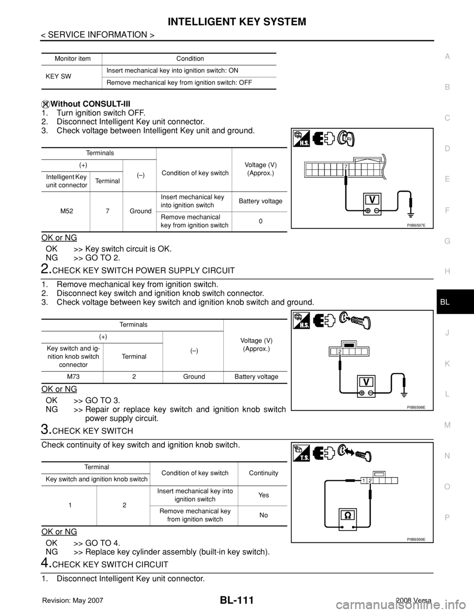
3. Check voltage between Intelligent Key unit and ground.
OK or NG
OK >> Key switch circuit is OK.
NG >> GO TO 2.
2.CHECK KEY SWITCH POWER SUPPLY CIRCUIT
1. Remove mechanical key from ignition switch.
2. Disconnect key switch and ignition knob switch connector.
3. Check voltage between key switch and ignition knob switch and ground.
OK or NG
OK >> GO TO 3.
NG >> Repair or replace key switch and ignition knob switch
power supply circuit.
3.CHECK KEY SWITCH
Check continuity of key switch and ignition knob switch.
OK or NG
OK >> GO TO 4.
NG >> Replace key cylinder assembly (built-in key switch).
4.CHECK KEY SWITCH CIRCUIT
1. Disconnect Intelligent Key unit connector.
Monitor item Condition
KEY SWInsert mechanical key into ignition switch: ON
Remove mechanical key from ignition switch: OFF
Te r m i n a l s
Condition of key switchVoltage (V)
(Approx.) (+)
(–)
Intelligent Key
unit connectorTe r m i n a l
M52 7 GroundInsert mechanical key
into ignition switchBattery voltage
Remove mechanical
key from ignition switch0
PIIB6597E
Te r m i n a l s
Voltage (V)
(Approx.) (+)
(–) Key switch and ig-
nition knob switch
connectorTe r m i n a l
M73 2 Ground Battery voltage
PIIB6598E
Te r m i n a l
Condition of key switch Continuity
Key switch and ignition knob switch
12Insert mechanical key into
ignition switchYe s
Remove mechanical key
from ignition switchNo
PIIB6599E