Page 570 of 2771
BL-136
< SERVICE INFORMATION >
INTELLIGENT KEY SYSTEM
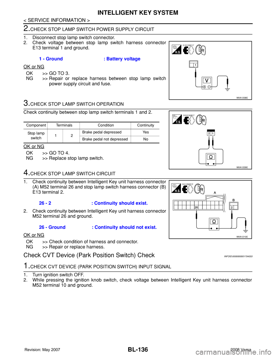
2.CHECK STOP LAMP SWITCH POWER SUPPLY CIRCUIT
1. Disconnect stop lamp switch connector.
2. Check voltage between stop lamp switch harness connector
E13 terminal 1 and ground.
OK or NG
OK >> GO TO 3.
NG >> Repair or replace harness between stop lamp switch
power supply circuit and fuse.
3.CHECK STOP LAMP SWITCH OPERATION
Check continuity between stop lamp switch terminals 1 and 2.
OK or NG
OK >> GO TO 4.
NG >> Replace stop lamp switch.
4.CHECK STOP LAMP SWITCH CIRCUIT
1. Check continuity between Intelligent Key unit harness connector
(A) M52 terminal 26 and stop lamp switch harness connector (B)
E13 terminal 2.
2. Check continuity between Intelligent Key unit harness connector
M52 terminal 26 and ground.
OK or NG
OK >> Check condition of harness and connector.
NG >> Repair or replace harness.
Check CVT Device (Park Position Switch) CheckINFOID:0000000001704033
1.CHECK CVT DEVICE (PARK POSITION SWITCH) INPUT SIGNAL
1. Turn ignition switch OFF.
2. While pressing the ignition knob switch, check voltage between Intelligent Key unit harness connector
M52 terminal 10 and ground.1 - Ground : Battery voltage
WIIA1208E
Component Terminals Condition Continuity
St op la mp
switch12Brake pedal depressed Yes
Brake pedal not depressed No
WIIA1209E
26 - 2 : Continuity should exist.
26 - Ground : Continuity should not exist.
WIIA1210E
Page 571 of 2771
INTELLIGENT KEY SYSTEM
BL-137
< SERVICE INFORMATION >
C
D
E
F
G
H
J
K
L
MA
B
BL
N
O
P
OK or NG
OK >> Replace Intelligent Key unit. Refer to BL-142, "Removal
and Installation of Intelligent Key Unit".
NG >> GO TO 2.
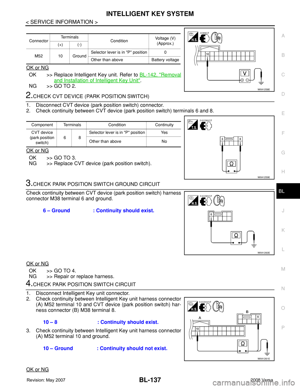
2.CHECK CVT DEVICE (PARK POSITION SWITCH)
1. Disconnect CVT device (park position switch) connector.
2. Check continuity between CVT device (park position switch) terminals 6 and 8.
OK or NG
OK >> GO TO 3.
NG >> Replace CVT device (park position switch).
3.CHECK PARK POSITION SWITCH GROUND CIRCUIT
Check continuity between CVT device (park position switch) harness
connector M38 terminal 6 and ground.
OK or NG
OK >> GO TO 4.
NG >> Repair or replace harness.
4.CHECK PARK POSITION SWITCH CIRCUIT
1. Disconnect Intelligent Key unit connector.
2. Check continuity between Intelligent Key unit harness connector
(A) M52 terminal 10 and CVT device (park position switch) har-
ness connector (B) M38 terminal 8.
3. Check continuity between Intelligent Key unit harness connector
(A) M52 terminal 10 and ground.
OK or NG
ConnectorTe r m i n a l s
ConditionVoltage (V)
(Approx.)
(+) (-)
M52 10 GroundSelector lever is in "P" position 0
Other than above Battery voltage
WIIA1258E
Component Terminals Condition Continuity
CVT device
(park position
switch)68Selector lever is in "P" position Yes
Other than above No
WIIA1259E
6 – Ground : Continuity should exist.
WIIA1260E
10 – 8 : Continuity should exist.
10 – Ground : Continuity should not exist.
WIIA1261E
Page 572 of 2771
BL-138
< SERVICE INFORMATION >
INTELLIGENT KEY SYSTEM
OK >> GO TO 5.
NG >> Repair or replace harness.
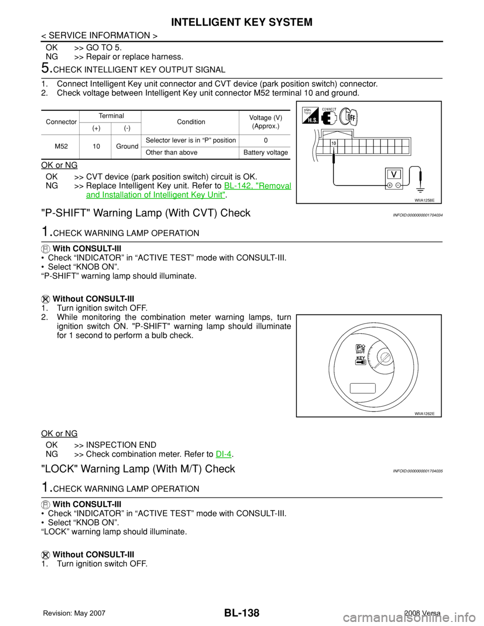
5.CHECK INTELLIGENT KEY OUTPUT SIGNAL
1. Connect Intelligent Key unit connector and CVT device (park position switch) connector.
2. Check voltage between Intelligent Key unit connector M52 terminal 10 and ground.
OK or NG
OK >> CVT device (park position switch) circuit is OK.
NG >> Replace Intelligent Key unit. Refer to BL-142, "
Removal
and Installation of Intelligent Key Unit".
"P-SHIFT" Warning Lamp (With CVT) CheckINFOID:0000000001704034
1.CHECK WARNING LAMP OPERATION
With CONSULT-III
• Check “INDICATOR” in “ACTIVE TEST” mode with CONSULT-III.
• Select “KNOB ON”.
“P-SHIFT” warning lamp should illuminate.
Without CONSULT-III
1. Turn ignition switch OFF.
2. While monitoring the combination meter warning lamps, turn
ignition switch ON. "P-SHIFT" warning lamp should illuminate
for 1 second to perform a bulb check.
OK or NG
OK >> INSPECTION END
NG >> Check combination meter. Refer to DI-4
.
"LOCK" Warning Lamp (With M/T) CheckINFOID:0000000001704035
1.CHECK WARNING LAMP OPERATION
With CONSULT-III
• Check “INDICATOR” in “ACTIVE TEST” mode with CONSULT-III.
• Select “KNOB ON”.
“LOCK” warning lamp should illuminate.
Without CONSULT-III
1. Turn ignition switch OFF.
ConnectorTe r m i n a l
ConditionVoltage (V)
(Approx.)
(+) (-)
M52 10 GroundSelector lever is in “P” position 0
Other than above Battery voltage
WIIA1258E
WIIA1262E
Page 575 of 2771
INTELLIGENT KEY SYSTEM
BL-141
< SERVICE INFORMATION >
C
D
E
F
G
H
J
K
L
MA
B
BL
N
O
P
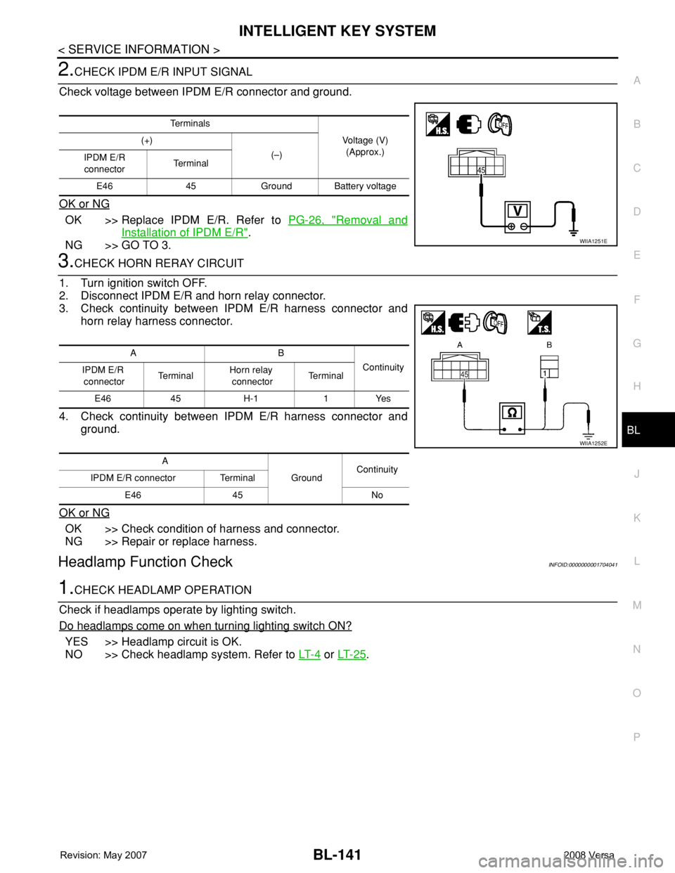
2.CHECK IPDM E/R INPUT SIGNAL
Check voltage between IPDM E/R connector and ground.
OK or NG
OK >> Replace IPDM E/R. Refer to PG-26, "Removal and
Installation of IPDM E/R".
NG >> GO TO 3.
3.CHECK HORN RERAY CIRCUIT
1. Turn ignition switch OFF.
2. Disconnect IPDM E/R and horn relay connector.
3. Check continuity between IPDM E/R harness connector and
horn relay harness connector.
4. Check continuity between IPDM E/R harness connector and
ground.
OK or NG
OK >> Check condition of harness and connector.
NG >> Repair or replace harness.
Headlamp Function CheckINFOID:0000000001704041
1.CHECK HEADLAMP OPERATION
Check if headlamps operate by lighting switch.
Do headlamps come on when turning lighting switch ON?
YES >> Headlamp circuit is OK.
NO >> Check headlamp system. Refer to LT- 4
or LT- 2 5.
Te r m i n a l s
Voltage (V)
(Approx.) (+)
(–)
IPDM E/R
connectorTe r m i n a l
E46 45 Ground Battery voltage
WIIA1251E
AB
Continuity
IPDM E/R
connectorTe r m i n a lHorn relay
connectorTe r m i n a l
E46 45 H-1 1 Yes
A
GroundContinuity
IPDM E/R connector Terminal
E46 45 No
WIIA1252E
Page 577 of 2771
INTELLIGENT KEY SYSTEM
BL-143
< SERVICE INFORMATION >
C
D
E
F
G
H
J
K
L
MA
B
BL
N
O
P
2. Disconnect Intelligent Key unit connector, remove screw and
Intelligent Key unit.
INSTALLATION
Installation is in the reverse order of removal.
PIIB6534E
Page 581 of 2771
DOOR
BL-147
< SERVICE INFORMATION >
C
D
E
F
G
H
J
K
L
MA
B
BL
N
O
P
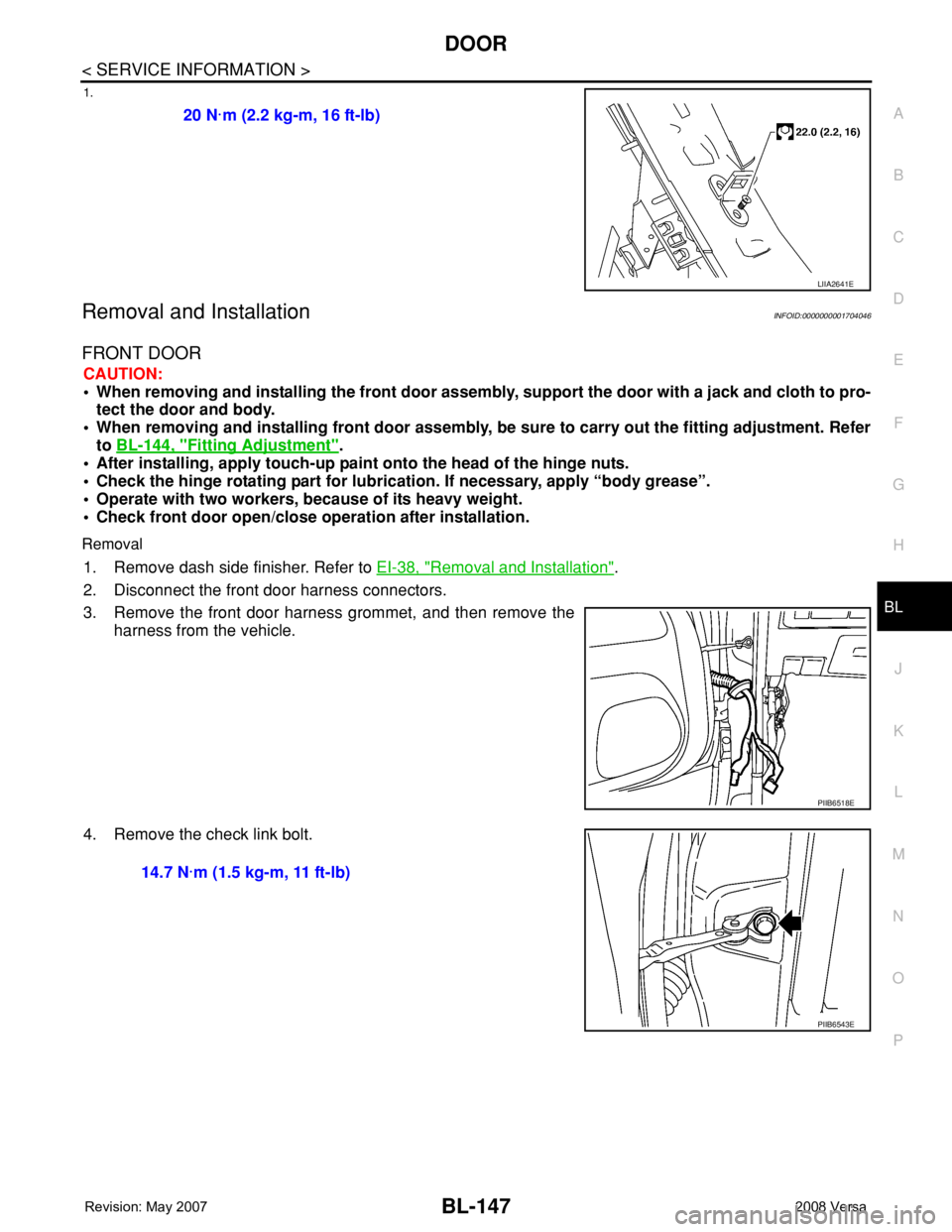
1.
Removal and InstallationINFOID:0000000001704046
FRONT DOOR
CAUTION:
• When removing and installing the front door assembly, support the door with a jack and cloth to pro-
tect the door and body.
• When removing and installing front door assembly, be sure to carry out the fitting adjustment. Refer
to BL-144, "
Fitting Adjustment".
• After installing, apply touch-up paint onto the head of the hinge nuts.
• Check the hinge rotating part for lubrication. If necessary, apply “body grease”.
• Operate with two workers, because of its heavy weight.
• Check front door open/close operation after installation.
Removal
1. Remove dash side finisher. Refer to EI-38, "Removal and Installation".
2. Disconnect the front door harness connectors.
3. Remove the front door harness grommet, and then remove the
harness from the vehicle.
4. Remove the check link bolt.20 N·m (2.2 kg-m, 16 ft-lb)
LIIA2641E
PIIB6518E
14.7 N·m (1.5 kg-m, 11 ft-lb)
PIIB6543E
Page 582 of 2771
BL-148
< SERVICE INFORMATION >
DOOR
5. Remove the hinge nuts and then the door assembly.
Installation
Installation is in the reverse order of removal.
REAR DOOR
CAUTION:
• When removing and installing the rear door assembly, support the door with a jack and cloth to pro-
tect the door and body.
• When removing and installing rear door assembly, be sure to carry out the fitting adjustment. Refer
to BL-144, "
Fitting Adjustment".
• After installing, apply touch-up paint onto the head of the hinge nuts.
• Check the hinge rotating part for poor lubrication. If necessary, apply “body grease”.
• Operate with two workers, because of its heavy weight.
• Check rear door open/close operation after installation.
Removal
1. Remove the rear door harness grommet.
2. Disconnect the rear door harness connector. 24.5 N·m (2.5 kg-m, 18 ft-lb)
PIIB6519E
PIIB6520E
PIIB6521E
Page 585 of 2771
FRONT DOOR LOCK
BL-151
< SERVICE INFORMATION >
C
D
E
F
G
H
J
K
L
MA
B
BL
N
O
P
8. Disconnect the inside handle cable and lock knob cable from the
inside handle.
CAUTION:
During removal and installation, work so as not to bend the
ends of the lock knob cable and inside handle cable.
9. Remove the door side grommet, and the door key cylinder
assembly (escutcheon) bolt.
10. Remove the key cylinder connecting rod (key cylinder side).
11. If equipped, disconnect the door antenna, the door request
switch connector and remove the harness clamp. (Vehicle with
intelligent key systems only).
12. Remove the door cylinder assembly while pulling the outside
handle forward.
13. Pull the outside door handle forward and then slide it toward the
rear of the vehicle to remove.
14. Remove the front and rear gaskets.
PIIB6525E
PIIB5808E
PIIB5809E
PIIB5810E
PIIB6526E