Page 477 of 2771
POWER DOOR LOCK SYSTEM
BL-43
< SERVICE INFORMATION >
C
D
E
F
G
H
J
K
L
MA
B
BL
N
O
P
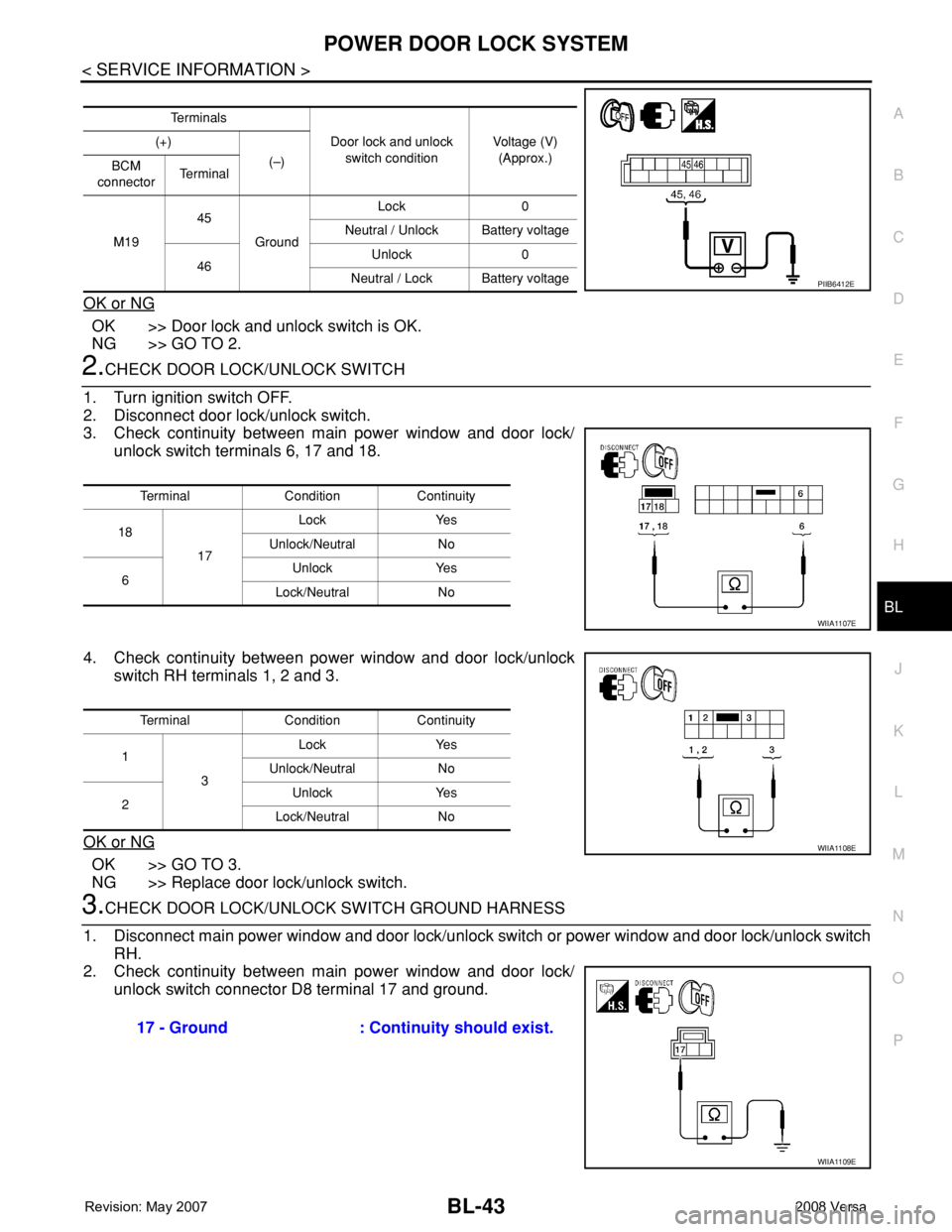
OK or NG
OK >> Door lock and unlock switch is OK.
NG >> GO TO 2.
2.CHECK DOOR LOCK/UNLOCK SWITCH
1. Turn ignition switch OFF.
2. Disconnect door lock/unlock switch.
3. Check continuity between main power window and door lock/
unlock switch terminals 6, 17 and 18.
4. Check continuity between power window and door lock/unlock
switch RH terminals 1, 2 and 3.
OK or NG
OK >> GO TO 3.
NG >> Replace door lock/unlock switch.
3.CHECK DOOR LOCK/UNLOCK SWITCH GROUND HARNESS
1. Disconnect main power window and door lock/unlock switch or power window and door lock/unlock switch
RH.
2. Check continuity between main power window and door lock/
unlock switch connector D8 terminal 17 and ground.
Te r m i n a l s
Door lock and unlock
switch conditionVoltage (V)
(Approx.) (+)
(–)
BCM
connectorTe r m i n a l
M1945
GroundLock 0
Neutral / Unlock Battery voltage
46Unlock 0
Neutral / Lock Battery voltage
PIIB6412E
Terminal Condition Continuity
18
17Lock Yes
Unlock/Neutral No
6Unlock Yes
Lock/Neutral No
WIIA1107E
Terminal Condition Continuity
1
3Lock Yes
Unlock/Neutral No
2Unlock Yes
Lock/Neutral No
WIIA1108E
17 - Ground : Continuity should exist.
WIIA1109E
Page 478 of 2771
BL-44
< SERVICE INFORMATION >
POWER DOOR LOCK SYSTEM
3. Check continuity between power window and door lock/unlock
switch RH connector D105 terminal 3 and ground
OK or NG
OK >> GO TO 4.
NG >> Repair or replace harness.
4.CHECK DOOR LOCK SWITCH CIRCUIT
1. Disconnect BCM.
2. Check continuity between BCM connector M19 (A) terminal 45 and main power window and door lock/
unlock switch connector D8 (B) terminal 18 or power window and door lock/unlock switch RH connector
D105 (C) terminal 1.
3. Check continuity between BCM connector M19 terminal 45 and
ground.
4. Check continuity between BCM connector M19 (A) terminal 46 and main power window and door lock/
unlock switch LH connector D7 (B) terminal 6 or power window and door lock/unlock switch RH connector
D105 (C) terminal 2.3 - Ground : Continuity should exist.
WIIA0450E
1 - 45 : Continuity should exist.
18 - 45 : Continuity should exist.
45 - Ground : Continuity should not exist.
W I I A 111 0 E
Page 479 of 2771
POWER DOOR LOCK SYSTEM
BL-45
< SERVICE INFORMATION >
C
D
E
F
G
H
J
K
L
MA
B
BL
N
O
P
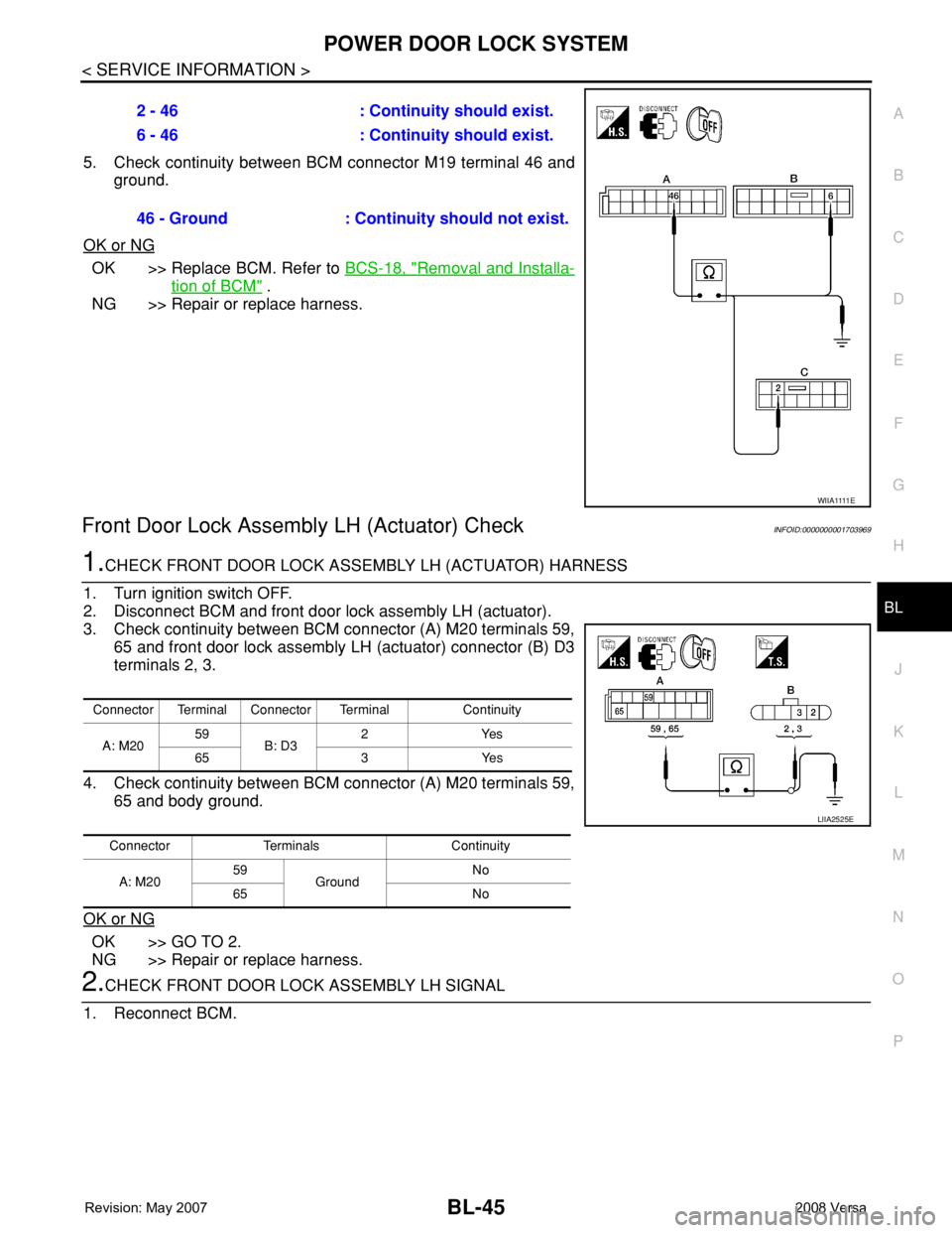
5. Check continuity between BCM connector M19 terminal 46 and
ground.
OK or NG
OK >> Replace BCM. Refer to BCS-18, "Removal and Installa-
tion of BCM" .
NG >> Repair or replace harness.
Front Door Lock Assembly LH (Actuator) CheckINFOID:0000000001703969
1.CHECK FRONT DOOR LOCK ASSEMBLY LH (ACTUATOR) HARNESS
1. Turn ignition switch OFF.
2. Disconnect BCM and front door lock assembly LH (actuator).
3. Check continuity between BCM connector (A) M20 terminals 59,
65 and front door lock assembly LH (actuator) connector (B) D3
terminals 2, 3.
4. Check continuity between BCM connector (A) M20 terminals 59,
65 and body ground.
OK or NG
OK >> GO TO 2.
NG >> Repair or replace harness.
2.CHECK FRONT DOOR LOCK ASSEMBLY LH SIGNAL
1. Reconnect BCM.2 - 46 : Continuity should exist.
6 - 46 : Continuity should exist.
46 - Ground : Continuity should not exist.
W I I A 1111 E
Connector Terminal Connector Terminal Continuity
A: M2059
B: D32Yes
65 3 Yes
Connector Terminals Continuity
A: M2059
GroundNo
65 No
LIIA2525E
Page 480 of 2771
BL-46
< SERVICE INFORMATION >
POWER DOOR LOCK SYSTEM
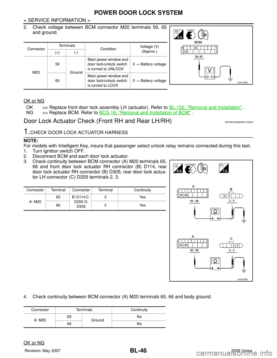
2. Check voltage between BCM connector M20 terminals 59, 65
and ground.
OK or NG
OK >> Replace front door lock assembly LH (actuator). Refer to BL-150, "Removal and Installation" .
NG >> Replace BCM. Refer to BCS-18, "
Removal and Installation of BCM" .
Door Lock Actuator Check (Front RH and Rear LH/RH)INFOID:0000000001703970
1.CHECK DOOR LOCK ACTUATOR HARNESS
NOTE:
For models with Intelligent Key, insure that passenger select unlock relay remains connected during this test.
1. Turn ignition switch OFF.
2. Disconnect BCM and each door lock actuator.
3. Check continuity between BCM connector (A) M20 terminals 65,
66 and front door lock actuator RH connector (B) D114, rear
door lock actuator RH connector (B) D305, rear door lock actua-
tor LH connector (C) D205 terminals 2, 3.
4. Check continuity between BCM connector (A) M20 terminals 65, 66 and body ground.
OK or NG
ConnectorTe r m i n a l s
ConditionVoltage (V)
(Approx.)
(+) (-)
M2059
GroundMain power window and
door lock/unlock switch
is turned to UNLOCK0 → Battery voltage
65Main power window and
door lock/unlock switch
is turned to LOCK0 → Battery voltage
LIIA1355E
Connector Terminal Connector Terminal Continuity
A: M2065 B: D114 C:
D205 D:
D3053Yes
66 2 Yes
LIIA2526E
Connector Terminals Continuity
A: M2065
GroundNo
66 No
Page 481 of 2771
POWER DOOR LOCK SYSTEM
BL-47
< SERVICE INFORMATION >
C
D
E
F
G
H
J
K
L
MA
B
BL
N
O
P
OK >> GO TO 2.
NG >> Check the following:
• Without Intelligent Key: Repair or replace harness.
• With Intelligent Key: For front doors, repair or replace harness.
• With Intelligent Key: For rear door, repair or replace harness or passenger select unlock relay.
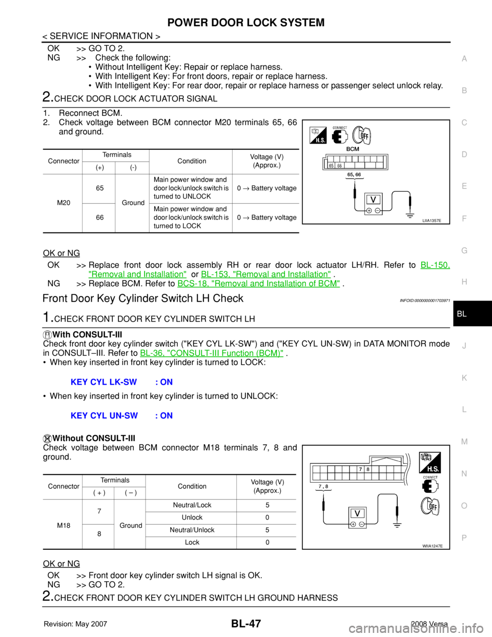
2.CHECK DOOR LOCK ACTUATOR SIGNAL
1. Reconnect BCM.
2. Check voltage between BCM connector M20 terminals 65, 66
and ground.
OK or NG
OK >> Replace front door lock assembly RH or rear door lock actuator LH/RH. Refer to BL-150,
"Removal and Installation" or BL-153, "Removal and Installation" .
NG >> Replace BCM. Refer to BCS-18, "
Removal and Installation of BCM" .
Front Door Key Cylinder Switch LH CheckINFOID:0000000001703971
1.CHECK FRONT DOOR KEY CYLINDER SWITCH LH
With CONSULT-III
Check front door key cylinder switch ("KEY CYL LK-SW") and ("KEY CYL UN-SW) in DATA MONITOR mode
in CONSULT–III. Refer to BL-36, "
CONSULT-III Function (BCM)" .
• When key inserted in front key cylinder is turned to LOCK:
• When key inserted in front key cylinder is turned to UNLOCK:
Without CONSULT-III
Check voltage between BCM connector M18 terminals 7, 8 and
ground.
OK or NG
OK >> Front door key cylinder switch LH signal is OK.
NG >> GO TO 2.
2.CHECK FRONT DOOR KEY CYLINDER SWITCH LH GROUND HARNESS
ConnectorTe r m i n a l s
ConditionVoltage (V)
(Approx.)
(+) (-)
M2065
GroundMain power window and
door lock/unlock switch is
turned to UNLOCK0 → Battery voltage
66Main power window and
door lock/unlock switch is
turned to LOCK0 → Battery voltage
LIIA1357E
KEY CYL LK-SW : ON
KEY CYL UN-SW : ON
ConnectorTe r m i n a l s
ConditionVoltage (V)
(Approx.)
( + ) ( – )
M187
GroundNeutral/Lock 5
Unlock 0
8Neutral/Unlock 5
Lock 0
WIIA1247E
Page 482 of 2771
BL-48
< SERVICE INFORMATION >
POWER DOOR LOCK SYSTEM
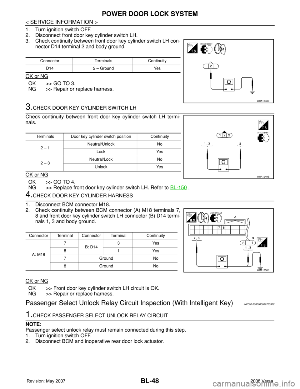
1. Turn ignition switch OFF.
2. Disconnect front door key cylinder switch LH.
3. Check continuity between front door key cylinder switch LH con-
nector D14 terminal 2 and body ground.
OK or NG
OK >> GO TO 3.
NG >> Repair or replace harness.
3.CHECK DOOR KEY CYLINDER SWITCH LH
Check continuity between front door key cylinder switch LH termi-
nals.
OK or NG
OK >> GO TO 4.
NG >> Replace front door key cylinder switch LH. Refer to BL-150
.
4.CHECK DOOR KEY CYLINDER HARNESS
1. Disconnect BCM connector M18.
2. Check continuity between BCM connector (A) M18 terminals 7,
8 and front door key cylinder switch LH connector (B) D14 termi-
nals 1, 3 and body ground.
OK or NG
OK >> Front door key cylinder switch LH circuit is OK.
NG >> Repair or replace harness.
Passenger Select Unlock Relay Circuit Inspection (With Intelligent Key)INFOID:0000000001703972
1.CHECK PASSENGER SELECT UNLOCK RELAY CIRCUIT
NOTE:
Passenger select unlock relay must remain connected during this step.
1. Turn ignition switch OFF.
2. Disconnect BCM and inoperative rear door lock actuator.
Connector Terminals Continuity
D14 2 – Ground Yes
WIIA1248E
Terminals Door key cylinder switch position Continuity
2 – 1 Neutral/Unlock No
Lock Yes
2 – 3Neutral/Lock No
Unlock Yes
WIIA1249E
Connector Terminal Connector Terminal Continuity
A: M187
B: D143Yes
81Yes
7Ground No
8Ground No
WIIA1250E
Page 483 of 2771
POWER DOOR LOCK SYSTEM
BL-49
< SERVICE INFORMATION >
C
D
E
F
G
H
J
K
L
MA
B
BL
N
O
P
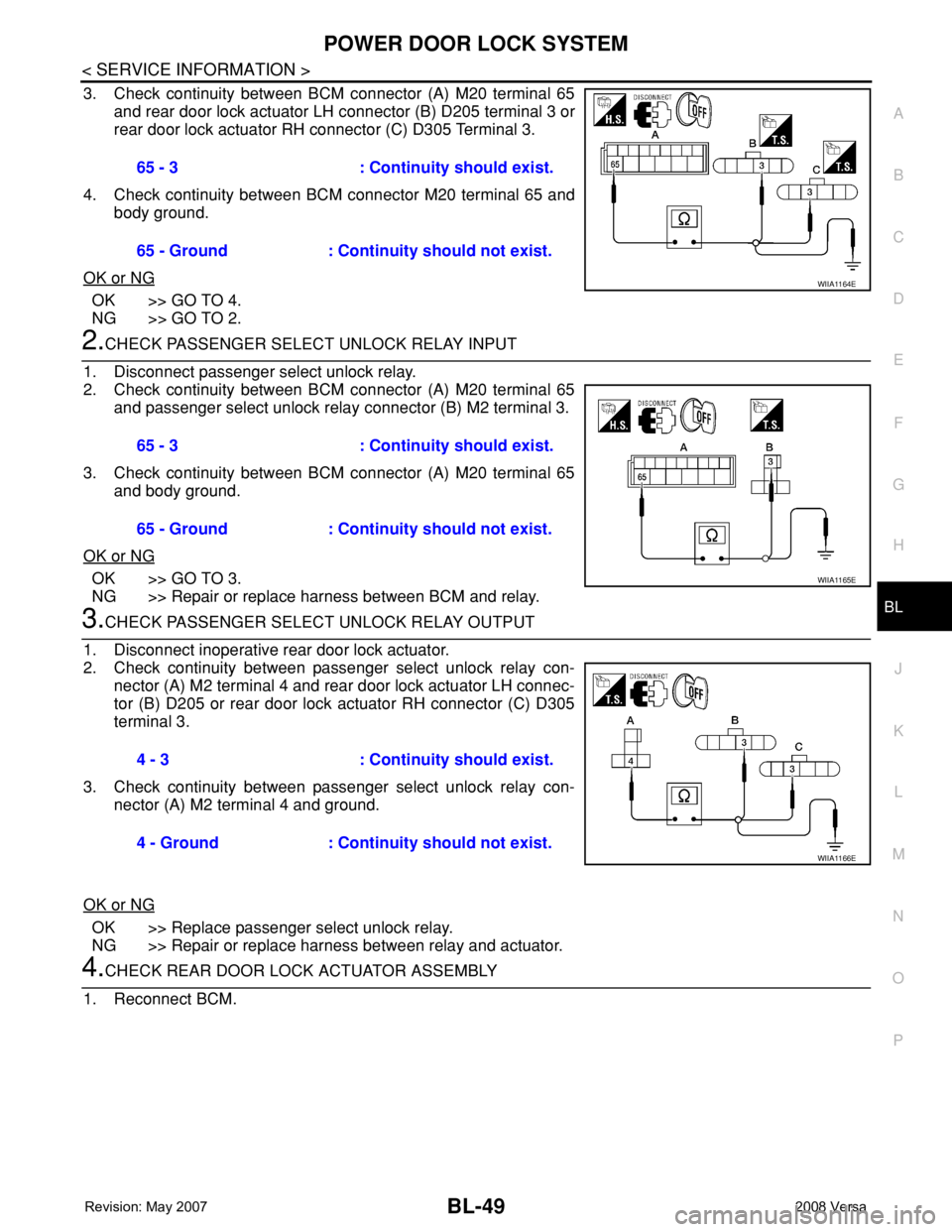
3. Check continuity between BCM connector (A) M20 terminal 65
and rear door lock actuator LH connector (B) D205 terminal 3 or
rear door lock actuator RH connector (C) D305 Terminal 3.
4. Check continuity between BCM connector M20 terminal 65 and
body ground.
OK or NG
OK >> GO TO 4.
NG >> GO TO 2.
2.CHECK PASSENGER SELECT UNLOCK RELAY INPUT
1. Disconnect passenger select unlock relay.
2. Check continuity between BCM connector (A) M20 terminal 65
and passenger select unlock relay connector (B) M2 terminal 3.
3. Check continuity between BCM connector (A) M20 terminal 65
and body ground.
OK or NG
OK >> GO TO 3.
NG >> Repair or replace harness between BCM and relay.
3.CHECK PASSENGER SELECT UNLOCK RELAY OUTPUT
1. Disconnect inoperative rear door lock actuator.
2. Check continuity between passenger select unlock relay con-
nector (A) M2 terminal 4 and rear door lock actuator LH connec-
tor (B) D205 or rear door lock actuator RH connector (C) D305
terminal 3.
3. Check continuity between passenger select unlock relay con-
nector (A) M2 terminal 4 and ground.
OK or NG
OK >> Replace passenger select unlock relay.
NG >> Repair or replace harness between relay and actuator.
4.CHECK REAR DOOR LOCK ACTUATOR ASSEMBLY
1. Reconnect BCM.65 - 3 : Continuity should exist.
65 - Ground : Continuity should not exist.
WIIA1164E
65 - 3 : Continuity should exist.
65 - Ground : Continuity should not exist.
WIIA1165E
4 - 3 : Continuity should exist.
4 - Ground : Continuity should not exist.
WIIA1166E
Page 484 of 2771
BL-50
< SERVICE INFORMATION >
POWER DOOR LOCK SYSTEM
2. Check voltage between rear door lock actuator connector LH (A)
D205 or rear door lock actuator connector RH (B) D305 termi-
nals 2 and 3.
3. Check voltage between rear door lock actuator connector LH (A)
D205 or rear door lock actuator connector RH (B) D305 termi-
nals 2 and 3.
OK or NG
OK >> Replace rear door lock actuator. Refer to BL-153, "Removal and Installation" .
NG >> Repair or replace harness between actuator and splice.
ConnectorTe r m i n a l s
ConditionVoltage (V)
(Approx.)
(+) (-)
A: D205 (LH)
B: D305 (RH)32Main power window and
door lock/unlock switch is
turned to LOCK0 → Battery voltage
WIIA1167E
ConnectorTe r m i n a l s
ConditionVoltage (V)
(Approx.)
(+) (-)
A: D205 (LH)
B: D305 (RH)23Main power window and
door lock/unlock switch is
turned to UNLOCK0 → Battery voltage
WIIA1216E