Page 397 of 2771
AV-38
< SERVICE INFORMATION >
AUDIO
Sedan
Removal
1. For hatchback, remove the luggage side lower finisher (LH) (hatchback only). Refer to EI-51.
2. For sedan, remove the trunk side finisher (LH). Refer to EI-53, "
Removal and Installation".
3. For hatchback remove the subwoofer. Refer to "SUBWOOFER".
4. Remove the satellite radio tuner bolts.
5. Disconnect the connectors and remove the satellite radio tuner.
6. If necessary, remove the upper bracket (2) and the lower
bracket (1).
Installation
Installation is in the reverse order of removal.
SATELLITE RADIO ANTENNA
Removal
1. Lower the headlining. Refer to EI-45.
LKIA0935E
1. Bracket (upper) 2. Satellite radio tuner 3. Bracket (lower)
A. Satellite radio tuner connector B. Satellite radio tuner feeder harness
connectorC. Satellite radio tuner bolts
⇒Front
LKIA0768E
Page 398 of 2771
AUDIO
AV-39
< SERVICE INFORMATION >
C
D
E
F
G
H
I
J
L
MA
B
AV
N
O
P
2. Disconnect the satellite radio antenna connectors.
3. Detach the satellite radio antenna feeder harness clips.
4. Remove the satellite radio antenna nut and remove the satellite
radio antenna from the roof.
Installation
Installation is in the reverse order of removal.
STEERING WHEEL AUDIO CONTROL SWITCHES
Removal
1. Remove the steering wheel. Refer to PS-7, "Removal and Installation".
2. Remove the steering wheel finisher cover.
3. Remove the screws and the steering wheel audio control switches.
Installation
Installation is in the reverse order of removal.
SUBWOOFER
LKIA0679E
1. Steering wheel finisher cover 2. Steering wheel 3. Steering wheel audio control switch-
es
A. Screws
LKIA0769E
Page 399 of 2771
AV-40
< SERVICE INFORMATION >
AUDIO
Removal
1. Remove the luggage side lower finisher (LH). Refer to EI-51.
2. Remove the subwoofer bolts.
3. Disconnect the connector and remove the subwoofer.
Installation
Installation is in the reverse order of removal.
1. Subwoofer A. Subwoofer bolts B. Connector
LKIA0770E
Page 400 of 2771
AUDIO ANTENNA
AV-41
< SERVICE INFORMATION >
C
D
E
F
G
H
I
J
L
MA
B
AV
N
O
P
AUDIO ANTENNA
Location of AntennaINFOID:0000000001704675
Removal and Installation of Roof AntennaINFOID:0000000001704676
REMOVAL
1. For hatchback, remove the luggage side upper finisher (LH). Refer to EI-51.
2. For sedan, remove the rear pillar finisher. Refer to EI-49, "
Removal and Installation - Sedan".
3. Remove rear assist grip (LH). Refer to EI-45
.
4. Remove three clips of headlining (rear side). Pull down headlining (rear side) and obtain space for work
between vehicle and headlining.
5. Disconnect the roof antenna harness connectors.
LKIA0934E
1. Roof antenna 2. Roof antenna base 3. Audio unit
A. Audio antenna harness connector B. Harness clips C. Roof antenna harness connectors
Page 402 of 2771

TELEPHONE
AV-43
< SERVICE INFORMATION >
C
D
E
F
G
H
I
J
L
MA
B
AV
N
O
P
TELEPHONE
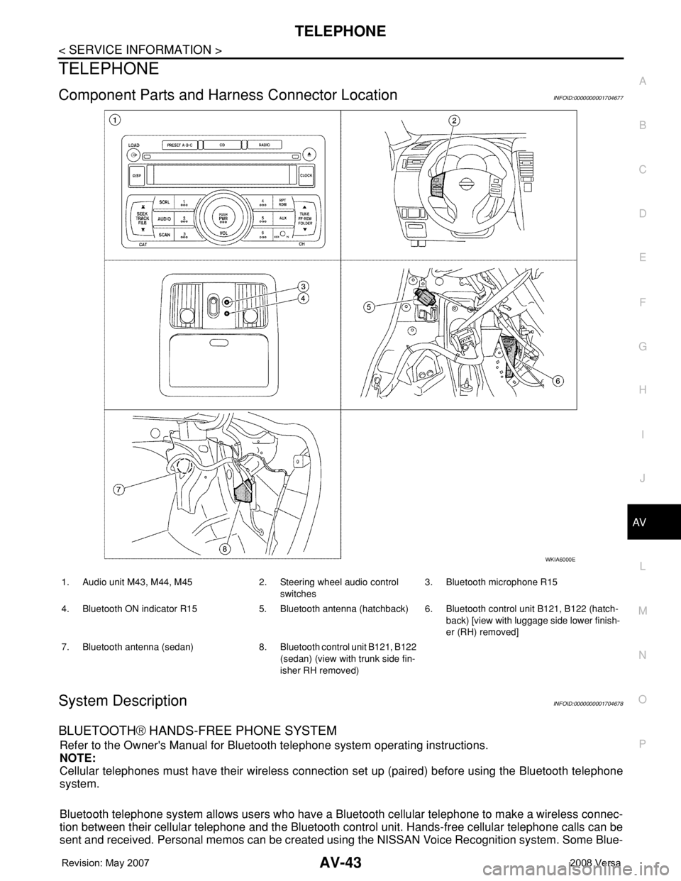
Component Parts and Harness Connector LocationINFOID:0000000001704677
System DescriptionINFOID:0000000001704678
BLUETOOTH® HANDS-FREE PHONE SYSTEM
Refer to the Owner's Manual for Bluetooth telephone system operating instructions.
NOTE:
Cellular telephones must have their wireless connection set up (paired) before using the Bluetooth telephone
system.
Bluetooth telephone system allows users who have a Bluetooth cellular telephone to make a wireless connec-
tion between their cellular telephone and the Bluetooth control unit. Hands-free cellular telephone calls can be
sent and received. Personal memos can be created using the NISSAN Voice Recognition system. Some Blue-
WKIA6000E
1. Audio unit M43, M44, M45 2. Steering wheel audio control
switches3. Bluetooth microphone R15
4. Bluetooth ON indicator R15 5. Bluetooth antenna (hatchback) 6. Bluetooth control unit B121, B122 (hatch-
back) [view with luggage side lower finish-
er (RH) removed]
7. Bluetooth antenna (sedan) 8. Bluetooth control unit B121, B122
(sedan) (view with trunk side fin-
isher RH removed)
Page 403 of 2771

AV-44
< SERVICE INFORMATION >
TELEPHONE
tooth cellular telephones may not be recognized by the Bluetooth control unit. When a cellular telephone or
the Bluetooth control unit is replaced, the telephone must be paired with the Bluetooth control unit. Different
cellular telephones may have different pairing procedures. Refer to the cellular telephone operating manual.
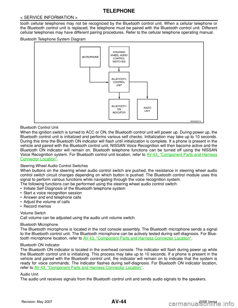
Bluetooth Telephone System Diagram
Bluetooth Control Unit
When the ignition switch is turned to ACC or ON, the Bluetooth control unit will power up. During power up, the
Bluetooth control unit is initialized and performs various self checks. Initialization may take up to 10 seconds.
During this time the Bluetooth ON indicator will flash until initialization is complete. If a phone is present in the
vehicle and paired with the Bluetooth control unit, NISSAN Voice Recognition will then become active and the
Bluetooth ON indicator will remain on. Bluetooth telephone functions can be turned off using the NISSAN
Voice Recognition system. For Bluetooth control unit location, refer to AV-43, "
Component Parts and Harness
Connector Location".
Steering Wheel Audio Control Switches
When buttons on the steering wheel audio control switch are pushed, the resistance in steering wheel audio
control switch circuit changes depending on which button is pushed. The Bluetooth control module uses this
signal to perform various functions while navigating through the voice recognition system.
The following functions can be performed using the steering wheel audio control switch:
• Initiate Self Diagnosis of the Bluetooth telephone system
• Start a voice recognition session
• Answer and end telephone calls
• Adjust the volume of calls
• Record memos
Volume Switch
Call volume can be adjusted using the audio unit volume switch.
Bluetooth Microphone
The Bluetooth microphone is located in the roof console assembly. The Bluetooth microphone sends a signal
to the Bluetooth control unit. The Bluetooth microphone can be actively tested during self-diagnosis. For Blue-
tooth microphone location, refer to AV-43, "
Component Parts and Harness Connector Location".
Bluetooth ON Indicator
The Bluetooth ON indicator is located in the overhead console. The indicator will flash during power up while
the Bluetooth control unit is initializing. This process may take up to 10 seconds. If a phone is present in the
vehicle and paired with the Bluetooth control unit, the indicator will remain on to indicate that the system is
ready for voice commands. The indicator flashes during self-diagnosis. For Bluetooth ON indicator location,
refer to AV-43, "
Component Parts and Harness Connector Location".
Audio Unit
The audio unit receives signals from the Bluetooth control unit and sends audio signals to the speakers.
WKIA6001E
Page 406 of 2771

TELEPHONE
AV-47
< SERVICE INFORMATION >
C
D
E
F
G
H
I
J
L
MA
B
AV
N
O
P
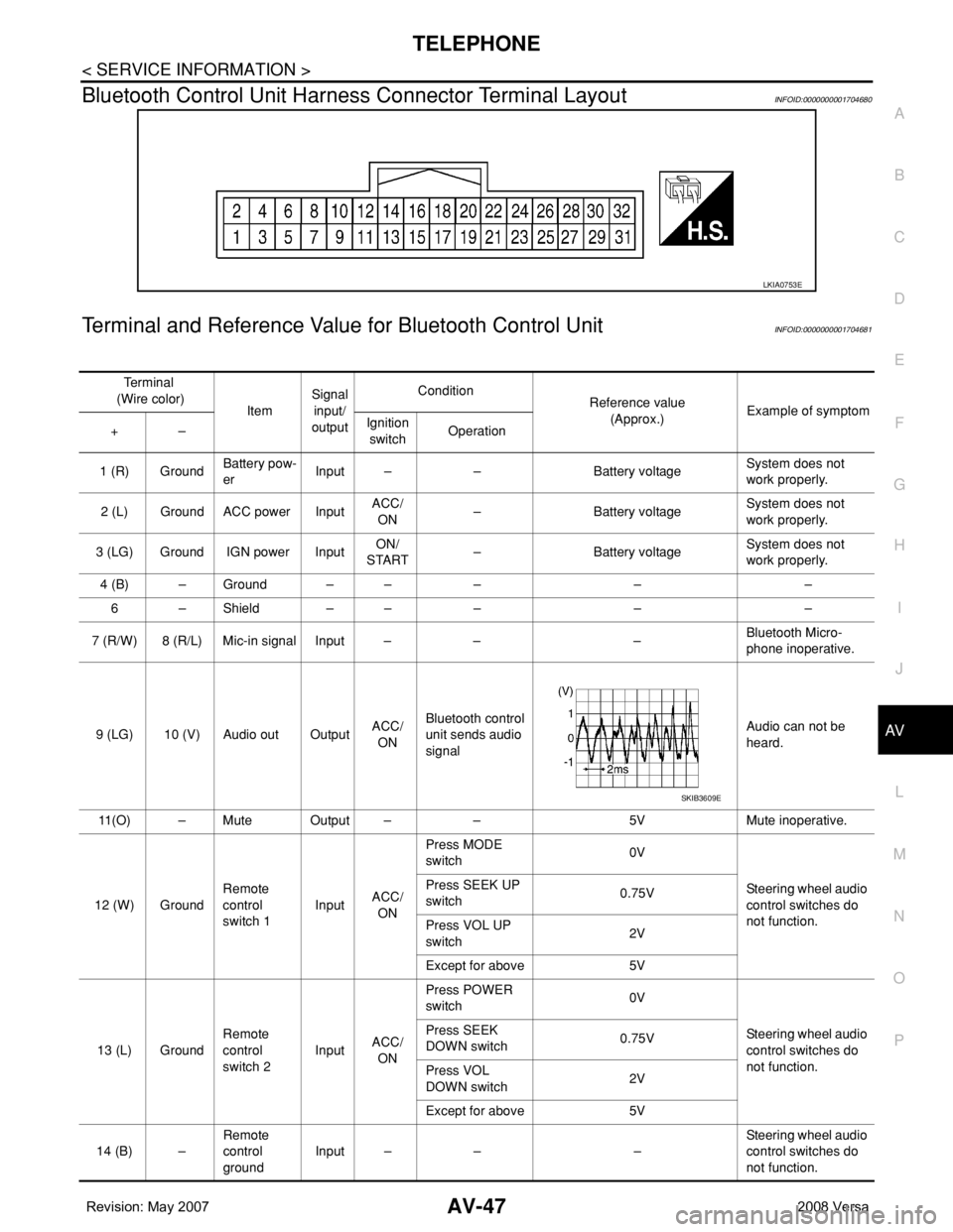
Bluetooth Control Unit Harness Connector Terminal LayoutINFOID:0000000001704680
Terminal and Reference Value for Bluetooth Control UnitINFOID:0000000001704681
LKIA0753E
Te r m i n a l
(Wire color)
ItemSignal
input/
outputCondition
Reference value
(Approx.)Example of symptom
+–Ignition
switchOperation
1 (R) GroundBattery pow-
erInput – – Battery voltageSystem does not
work properly.
2 (L) Ground ACC power InputACC/
ON– Battery voltageSystem does not
work properly.
3 (LG) Ground IGN power InputON/
START– Battery voltageSystem does not
work properly.
4 (B) – Ground – – – – –
6 – Shield – – – – –
7 (R/W) 8 (R/L) Mic-in signal Input – – –Bluetooth Micro-
phone inoperative.
9 (LG) 10 (V) Audio out OutputACC/
ONBluetooth control
unit sends audio
signalAudio can not be
heard.
11(O) – Mute Output – – 5V Mute inoperative.
12 (W) GroundRemote
control
switch 1InputACC/
ONPress MODE
switch 0V
Steering wheel audio
control switches do
not function. Press SEEK UP
switch0.75V
Press VOL UP
switch2V
Except for above 5V
13 (L) GroundRemote
control
switch 2InputACC/
ONPress POWER
switch 0V
Steering wheel audio
control switches do
not function. Press SEEK
DOWN switch0.75V
Press VOL
DOWN switch2V
Except for above 5V
14 (B) –Remote
control
groundInput – – –Steering wheel audio
control switches do
not function.
SKIB3609E
Page 409 of 2771

AV-50
< SERVICE INFORMATION >
TELEPHONE
OK or NG
OK >> GO TO 2.
NG >> If fuse is blown, be sure to eliminate cause of malfunction before installing new fuse. Refer to PG-
3.
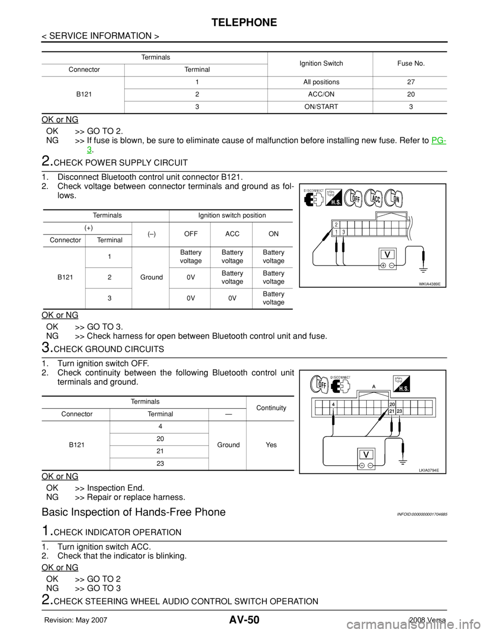
2.CHECK POWER SUPPLY CIRCUIT
1. Disconnect Bluetooth control unit connector B121.
2. Check voltage between connector terminals and ground as fol-
lows.
OK or NG
OK >> GO TO 3.
NG >> Check harness for open between Bluetooth control unit and fuse.
3.CHECK GROUND CIRCUITS
1. Turn ignition switch OFF.
2. Check continuity between the following Bluetooth control unit
terminals and ground.
OK or NG
OK >> Inspection End.
NG >> Repair or replace harness.
Basic Inspection of Hands-Free PhoneINFOID:0000000001704685
1.CHECK INDICATOR OPERATION
1. Turn ignition switch ACC.
2. Check that the indicator is blinking.
OK or NG
OK >> GO TO 2
NG >> GO TO 3
2.CHECK STEERING WHEEL AUDIO CONTROL SWITCH OPERATION
Te r m i n a l s
Ignition Switch Fuse No.
Connector Terminal
B1211 All positions 27
2 ACC/ON 20
3 ON/START 3
Terminals Ignition switch position
(+)
(–) OFF ACC ON
Connector Terminal
B1211
GroundBattery
voltageBattery
voltageBattery
voltage
20VBattery
voltageBattery
voltage
30V0VBattery
voltage
WKIA4389E
Te r m i n a l s
Continuity
Connector Terminal —
B1214
Ground Yes 20
21
23
LKIA0794E