Page 215 of 2771
SHIFT CONTROL SYSTEM
AT-203
< SERVICE INFORMATION >
D
E
F
G
H
I
J
K
L
MA
B
AT
N
O
P
SHIFT CONTROL SYSTEM
Control Device Removal and InstallationINFOID:0000000001703356
CONTROL DEVICE COMPONENTS
CONTROL CABLE COMPONENTS
1. Selector lever knob 2. Knob cover 3. Lock pin
4. Overdrive control switch 5. Knob finisher 6. Selector button
7. Selector button return spring 8. Position indicator plate 9. Position lamp
10. Dust cover 11. Bracket 12. Shift lock solenoid and park position
switch assembly
13. A/T device harness connector 14. Plate 15. Control device assembly
WCIA0638E
Page 216 of 2771
AT-204
< SERVICE INFORMATION >
SHIFT CONTROL SYSTEM
REMOVAL
CAUTION:
Make sure that parking brake is applied before removal/installation.
1. Place the selector lever in the “N” position.
2. Remove the center console assembly. Refer to IP-10
.
3. Disconnect the A/T device harness connector (1).
4. Remove the key interlock cable from the control device assem-
bly. Refer to AT-213, "
Removal and Installation".
5. Remove the bolts (A) from the control device assembly (1).
6. Remove exhaust front tube, center muffler and heat plates.
Refer to EM-21
.
1. Selector lever knob 2. Control device assembly 3. Lock plate
4. Floor panel 5. Control cable 6. Bracket
7. Lock plate 8. Lock nut 9. A/T assembly
10. Bracket 11. Bracket
WCIA0640E
SCIA6965E
WCIA0609E
Page 218 of 2771

AT-206
< SERVICE INFORMATION >
SHIFT CONTROL SYSTEM
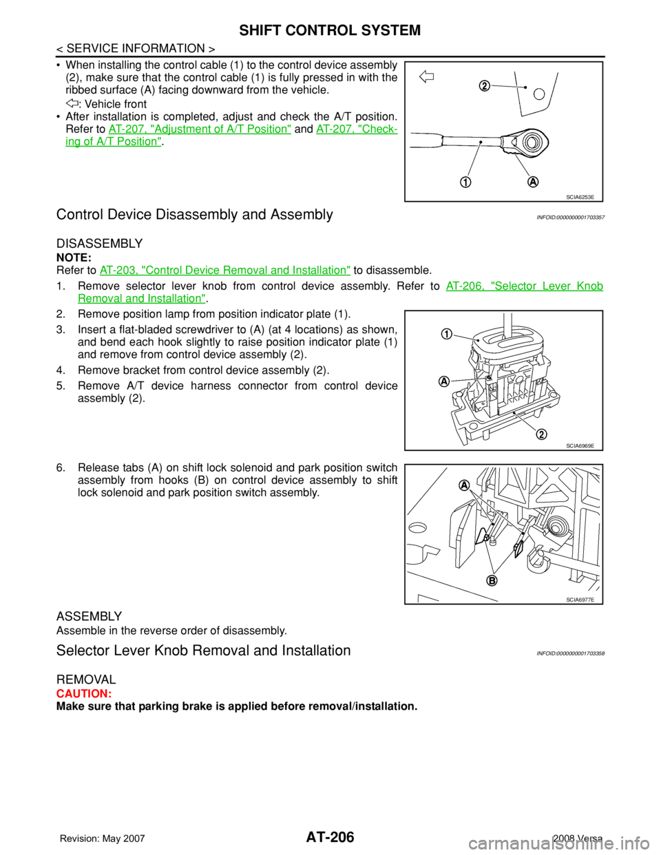
• When installing the control cable (1) to the control device assembly
(2), make sure that the control cable (1) is fully pressed in with the
ribbed surface (A) facing downward from the vehicle.
: Vehicle front
• After installation is completed, adjust and check the A/T position.
Refer to AT-207, "
Adjustment of A/T Position" and AT-207, "Check-
ing of A/T Position".
Control Device Disassembly and AssemblyINFOID:0000000001703357
DISASSEMBLY
NOTE:
Refer to AT-203, "
Control Device Removal and Installation" to disassemble.
1. Remove selector lever knob from control device assembly. Refer to AT-206, "
Selector Lever Knob
Removal and Installation".
2. Remove position lamp from position indicator plate (1).
3. Insert a flat-bladed screwdriver to (A) (at 4 locations) as shown,
and bend each hook slightly to raise position indicator plate (1)
and remove from control device assembly (2).
4. Remove bracket from control device assembly (2).
5. Remove A/T device harness connector from control device
assembly (2).
6. Release tabs (A) on shift lock solenoid and park position switch
assembly from hooks (B) on control device assembly to shift
lock solenoid and park position switch assembly.
ASSEMBLY
Assemble in the reverse order of disassembly.
Selector Lever Knob Removal and InstallationINFOID:0000000001703358
REMOVAL
CAUTION:
Make sure that parking brake is applied before removal/installation.
SCIA6253E
SCIA6969E
SCIA6977E
Page 223 of 2771

A/T SHIFT LOCK SYSTEM
AT-211
< SERVICE INFORMATION >
D
E
F
G
H
I
J
K
L
MA
B
AT
N
O
P
•Selector lever can be moved from “P” position with ignition key in ON position and brake pedal
released.
•Selector lever can be moved from “P” position when ignition switch is removed from key cylinder.
SYMPTOM 2:
•Ignition key cannot be removed when selector lever is set to “P” position.
•Ignition key can be removed when selector lever is set to any position except “P” position.
1.CHECK KEY INTERLOCK CABLE
Check key interlock cable for damage.
OK or NG
OK >> GO TO 2.
NG >> Repair key interlock cable. Refer to AT-213, "
Removal and Installation" .
2.CHECK A/T POSITION
Check A/T position. Refer to AT-207, "
Checking of A/T Position" .
OK or NG
OK >> GO TO 3.
NG >> Adjust control cable. Refer to AT-207, "
Adjustment of A/T Position" .
3.CHECK SHIFT LOCK SOLENOID AND PARK POSITION SWITCH
1. Turn ignition switch ON. (Do not start engine.)
2. Selector lever is set in “P” position.
3. Check operation sound.
OK or NG
OK >>INSPECTION END
NG >> GO TO 4.
4.CHECK POWER SOURCE
1. Turn ignition switch ON. (Do not start engine.)
2. Check voltage between A/T device harness connector terminal
5 and ground.
OK or NG
OK >> GO TO 7.
NG >> GO TO 5.
5.CHECK STOP LAMP SWITCH
1. Turn ignition switch OFF.
2. Disconnect stop lamp switch harness connector.
Condition Brake pedal Operation sound
When ignition switch is turned to ON position and selector lever is set in
“P” position.Depressed Yes
Released No
Voltage:
Brake pedal depressed: Battery voltage
Brake pedal released: 0V
SCIA7171E
Page 224 of 2771

AT-212
< SERVICE INFORMATION >
A/T SHIFT LOCK SYSTEM
3. Check continuity between stop lamp switch harness connector
terminals 3 and 4.
Check stop lamp switch after adjusting brake pedal. Refer to
BR-5
.
OK or NG
OK >> GO TO 6.
NG >> Repair or replace damaged parts.
6.DETECT MALFUNCTIONING ITEM
Check the following. If any items are damaged, repair or replace damaged parts.
• Harness for short or open between ignition switch and stop lamp switch harness connector
• Harness for short or open between stop lamp switch harness connector and A/T device harness connector
• 10A fuse [No.3, located in the fuse block (J/B)]
• Ignition switch, Refer to PG-3
.
OK or NG
OK >>INSPECTION END
NG >> Repair or replace damaged parts.
7.CHECK GROUND CIRCUIT
1. Turn ignition switch OFF.
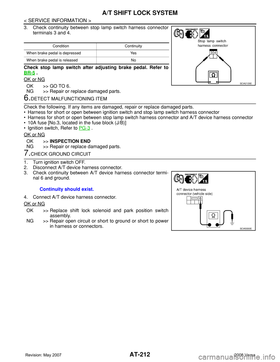
2. Disconnect A/T device harness connector.
3. Check continuity between A/T device harness connector termi-
nal 6 and ground.
4. Connect A/T device harness connector.
OK or NG
OK >> Replace shift lock solenoid and park position switch
assembly.
NG >> Repair open circuit or short to ground or short to power
in harness or connectors.
Condition Continuity
When brake pedal is depressed Yes
When brake pedal is released No
SCIA2126E
Continuity should exist.
SCIA5000E
Page 229 of 2771

ON-VEHICLE SERVICE
AT-217
< SERVICE INFORMATION >
D
E
F
G
H
I
J
K
L
MA
B
AT
N
O
P
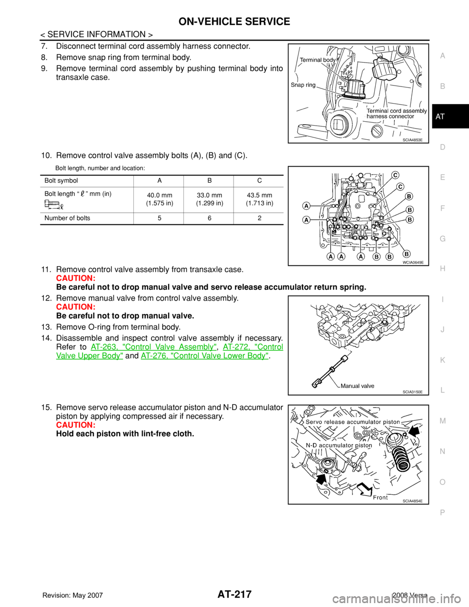
7. Disconnect terminal cord assembly harness connector.
8. Remove snap ring from terminal body.
9. Remove terminal cord assembly by pushing terminal body into
transaxle case.
10. Remove control valve assembly bolts (A), (B) and (C).
Bolt length, number and location:
11. Remove control valve assembly from transaxle case.
CAUTION:
Be careful not to drop manual valve and servo release accumulator return spring.
12. Remove manual valve from control valve assembly.
CAUTION:
Be careful not to drop manual valve.
13. Remove O-ring from terminal body.
14. Disassemble and inspect control valve assembly if necessary.
Refer to AT-263, "
Control Valve Assembly", AT-272, "Control
Valve Upper Body" and AT-276, "Control Valve Lower Body".
15. Remove servo release accumulator piston and N-D accumulator
piston by applying compressed air if necessary.
CAUTION:
Hold each piston with lint-free cloth.
SCIA4853E
Bolt symbol A B C
Bolt length “ ” mm (in)
40.0 mm
(1.575 in)33.0 mm
(1.299 in)43.5 mm
(1.713 in)
Number of bolts 5 6 2
WCIA0649E
SCIA3150E
SCIA4854E
Page 232 of 2771

AT-220
< SERVICE INFORMATION >
ON-VEHICLE SERVICE
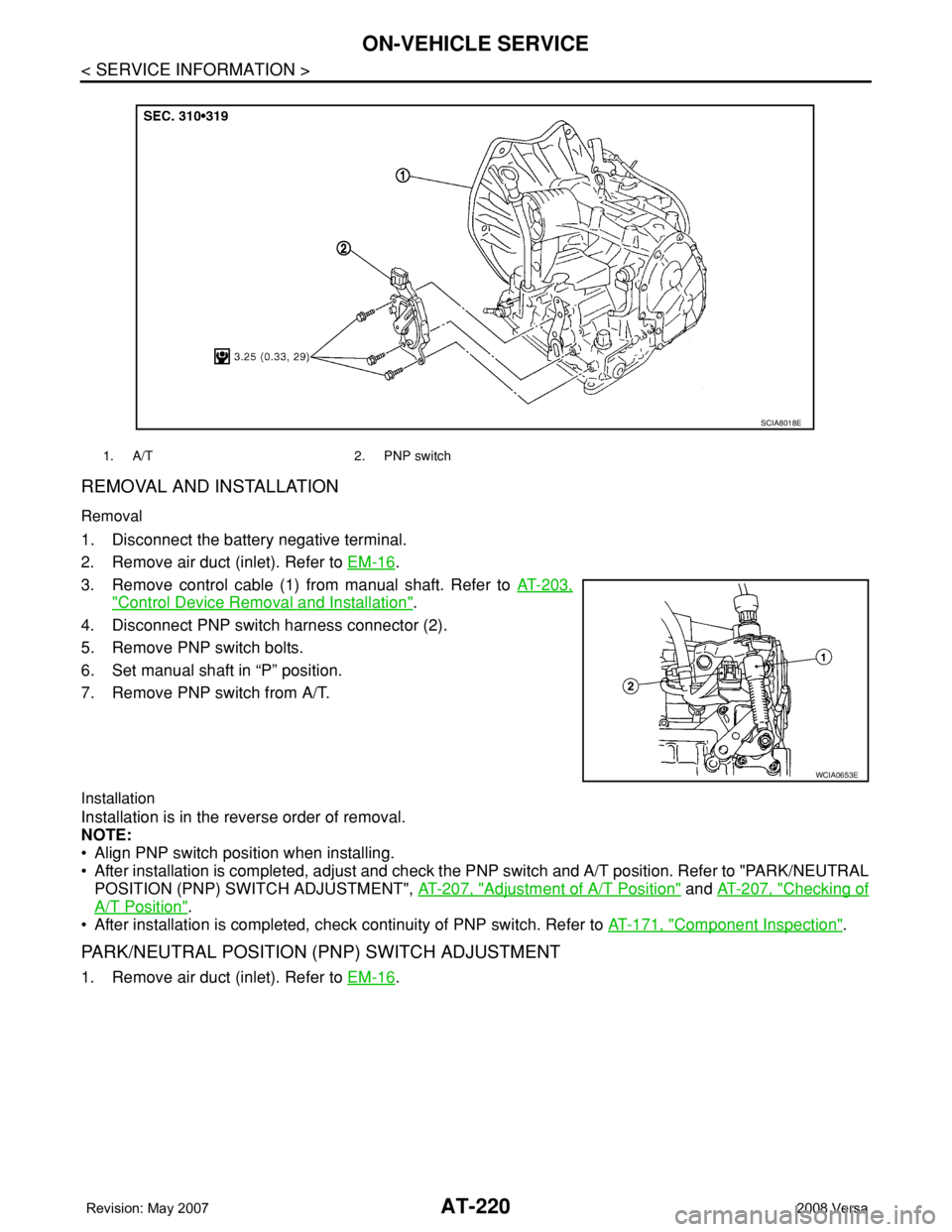
REMOVAL AND INSTALLATION
Removal
1. Disconnect the battery negative terminal.
2. Remove air duct (inlet). Refer to EM-16
.
3. Remove control cable (1) from manual shaft. Refer to AT-203,
"Control Device Removal and Installation".
4. Disconnect PNP switch harness connector (2).
5. Remove PNP switch bolts.
6. Set manual shaft in “P” position.
7. Remove PNP switch from A/T.
Installation
Installation is in the reverse order of removal.
NOTE:
• Align PNP switch position when installing.
• After installation is completed, adjust and check the PNP switch and A/T position. Refer to "PARK/NEUTRAL
POSITION (PNP) SWITCH ADJUSTMENT", AT-207, "
Adjustment of A/T Position" and AT-207, "Checking of
A/T Position".
• After installation is completed, check continuity of PNP switch. Refer to AT-171, "
Component Inspection".
PARK/NEUTRAL POSITION (PNP) SWITCH ADJUSTMENT
1. Remove air duct (inlet). Refer to EM-16.
1. A/T 2. PNP switch
SCIA8018E
WCIA0653E
Page 234 of 2771
AT-222
< SERVICE INFORMATION >
ON-VEHICLE SERVICE
3. Disconnect revolution sensor harness connector.
4. Remove clip (A).
5. Remove revolution sensor (1) from A/T.
: Bolt (2)
6. Remove O-ring from revolution sensor (1)
Installation
Installation is in the reverse order of removal.
CAUTION:
• Do not reuse O-ring.
• Apply ATF to O-ring.
• Ensure revolution sensor harness is firmly secured with bolt.
(1): Revolution sensor
: Bolt (1)
Turbine Revolution Sensor (Power Train Revolution Sensor)INFOID:0000000001703369
COMPONENTS
REMOVAL AND INSTALLATION
Removal
1. Disconnect the battery negative terminal.
2. Remove air duct (inlet). Refer to EM-16
.
WCIA0655E
WCIA0656E
1. A/T 2. O-ring 3. Turbine revolution sensor (power
train revolution sensor)
SCIA8020E