2008 NISSAN TIIDA connector d2
[x] Cancel search: connector d2Page 235 of 2771
ON-VEHICLE SERVICE
AT-223
< SERVICE INFORMATION >
D
E
F
G
H
I
J
K
L
MA
B
AT
N
O
P
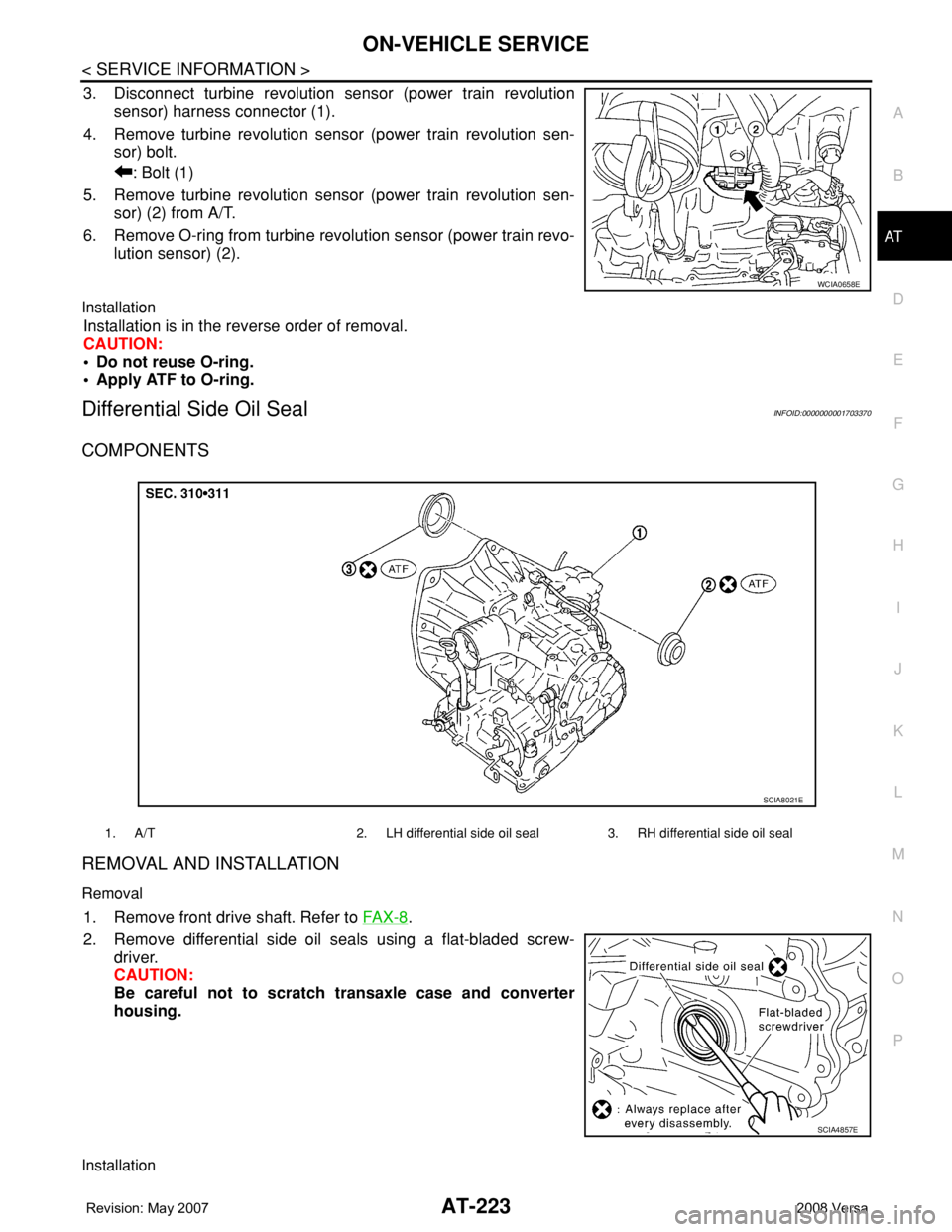
3. Disconnect turbine revolution sensor (power train revolution
sensor) harness connector (1).
4. Remove turbine revolution sensor (power train revolution sen-
sor) bolt.
: Bolt (1)
5. Remove turbine revolution sensor (power train revolution sen-
sor) (2) from A/T.
6. Remove O-ring from turbine revolution sensor (power train revo-
lution sensor) (2).
Installation
Installation is in the reverse order of removal.
CAUTION:
• Do not reuse O-ring.
• Apply ATF to O-ring.
Differential Side Oil SealINFOID:0000000001703370
COMPONENTS
REMOVAL AND INSTALLATION
Removal
1. Remove front drive shaft. Refer to FA X - 8.
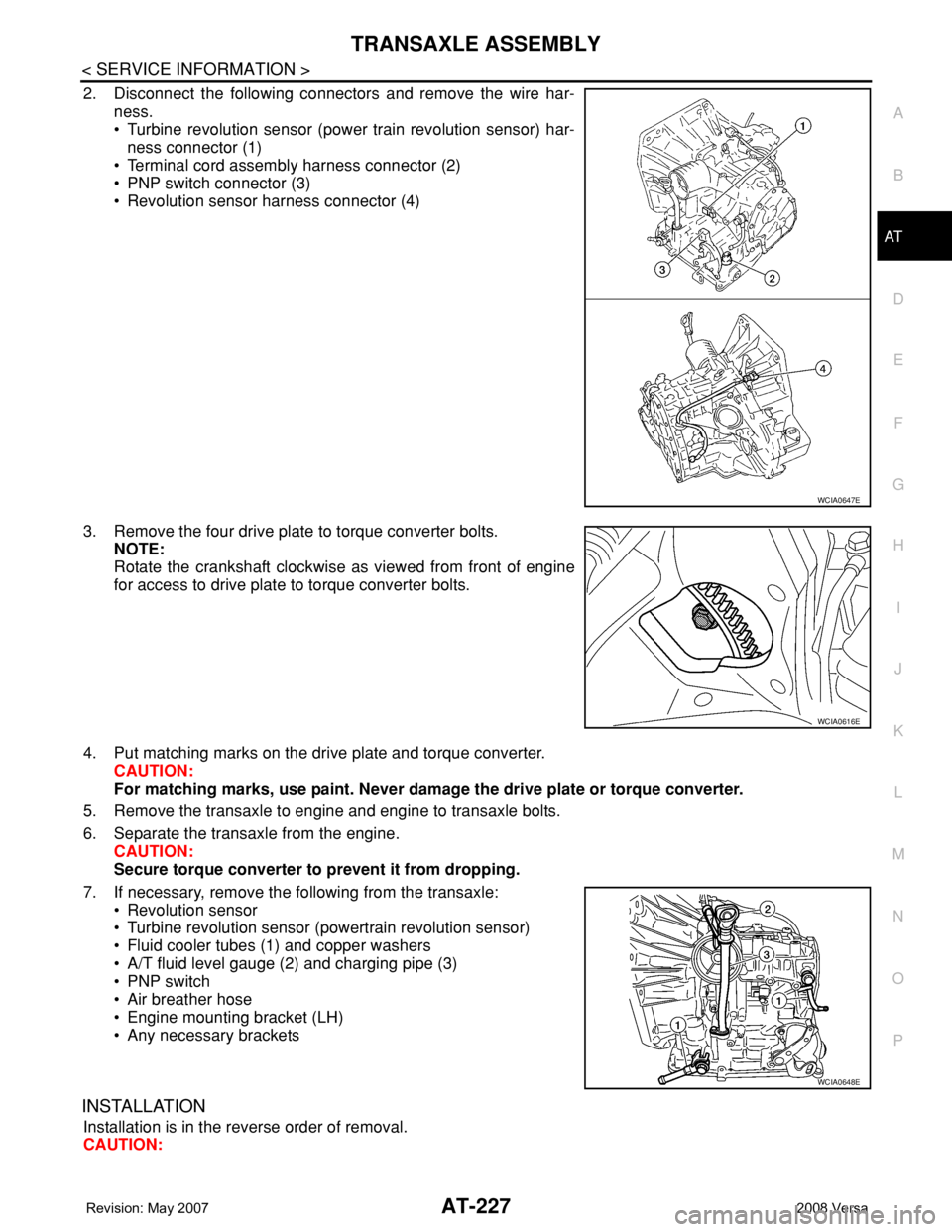
2. Remove differential side oil seals using a flat-bladed screw-
driver.
CAUTION:
Be careful not to scratch transaxle case and converter
housing.
Installation
WCIA0658E
1. A/T 2. LH differential side oil seal 3. RH differential side oil seal
SCIA8021E
SCIA4857E
Page 239 of 2771
TRANSAXLE ASSEMBLY
AT-227
< SERVICE INFORMATION >
D
E
F
G
H
I
J
K
L
MA
B
AT
N
O
P
2. Disconnect the following connectors and remove the wire har-
ness.
• Turbine revolution sensor (power train revolution sensor) har-
ness connector (1)
• Terminal cord assembly harness connector (2)
• PNP switch connector (3)
• Revolution sensor harness connector (4)
3. Remove the four drive plate to torque converter bolts.
NOTE:
Rotate the crankshaft clockwise as viewed from front of engine
for access to drive plate to torque converter bolts.
4. Put matching marks on the drive plate and torque converter.
CAUTION:
For matching marks, use paint. Never damage the drive plate or torque converter.
5. Remove the transaxle to engine and engine to transaxle bolts.
6. Separate the transaxle from the engine.
CAUTION:
Secure torque converter to prevent it from dropping.
7. If necessary, remove the following from the transaxle:
• Revolution sensor
• Turbine revolution sensor (powertrain revolution sensor)
• Fluid cooler tubes (1) and copper washers
• A/T fluid level gauge (2) and charging pipe (3)
• PNP switch
• Air breather hose
• Engine mounting bracket (LH)
• Any necessary brackets
INSTALLATION
Installation is in the reverse order of removal.
CAUTION:
WCIA0647E
WCIA0616E
WCIA0648E
Page 360 of 2771
AV-1
ELECTRICAL
C
D
E
F
G
H
I
J
L
M
SECTION AV
A
B
AV
N
O
P
CONTENTS
AUDIO, VISUAL, NAVIGATION & TELEPHONE SYS-
TEM
SERVICE INFORMATION ............................2
PRECAUTIONS ...................................................2
Precaution for Supplemental Restraint System
(SRS) "AIR BAG" and "SEAT BELT PRE-TEN-
SIONER" ...................................................................
2
PREPARATION ...................................................3
Commercial Service Tool ..........................................3
AUDIO .................................................................4
Component Parts Location ........................................4
System Description ...................................................4
Schematic .................................................................6
Wiring Diagram - AUDIO - .........................................8
Audio Unit (Base System) Harness Connector
Terminal Layout ......................................................
15
Terminal and Reference Value for Audio Unit
(Base System) .........................................................
15
Audio Unit (Mid Level and Premium System) Har-
ness Connector Terminal Layout ............................
16
Terminal and Reference Value for Audio Unit (Mid
Level and Premium System) ...................................
16
Subwoofer Harness Connector Terminal Layout
(Premium Audio System) ........................................
19
Terminal and Reference Value for Subwoofer
(Premium Audio System) ........................................
19
Satellite Radio Tuner Harness Connector Termi-
nal Layout ................................................................
19
Terminal and Reference Value for Satellite Radio
Tuner .......................................................................
20
Trouble Diagnosis ...................................................20
Noise Inspection ......................................................21
Power Supply Circuit Inspection .............................22
Satellite Radio Tuner (Factory Installed) Power
and Ground Supply Circuit Inspection .....................
23
Satellite Radio Tuner (Factory Installed) Commu-
nication Circuit Inspection .......................................
24
Satellite Radio Tuner (Factory Installed) Left
Channel Audio Signal Circuit Inspection .................
26
Satellite Radio Tuner (Factory Installed) Right
Channel Audio Signal Circuit Inspection .................
26
Steering Switch Check (With Bluetooth) ..................27
Sound Is Not Heard from Front Door Speaker
(Base System) .........................................................
29
Sound Is Not Heard from Rear Door Speaker
(Base System) .........................................................
30
Sound Is Not Heard from Front Door Speaker or
Tweeter (Mid Level and Premium System) .............
31
Sound Is Not Heard from Rear Door Speaker (Mid
Level and Premium System) ...................................
32
Sound Is Not Heard from Subwoofer (Premium
System) ...................................................................
34
Removal and Installation .........................................36
AUDIO ANTENNA .............................................41
Location of Antenna .................................................41
Removal and Installation of Roof Antenna ..............41
TELEPHONE .....................................................43
Component Parts and Harness Connector Loca-
tion ...........................................................................
43
System Description ..................................................43
Wiring Diagram - H/PHON - ....................................45
Bluetooth Control Unit Harness Connector Termi-
nal Layout ................................................................
47
Terminal and Reference Value for Bluetooth Con-
trol Unit ....................................................................
47
Bluetooth Control Unit Self-Diagnosis Function ......48
Workflow ..................................................................49
Power Supply and Ground Circuit Inspection for
Bluetooth Control Unit .............................................
49
Basic Inspection of Hands-Free Phone ...................50
Steering Wheel Audio Control Switch Does Not
Operate ....................................................................
51
Voice Activated Control Function Does Not Oper-
ate ............................................................................
52
Removal and Installation .........................................54
Page 361 of 2771
AV-2
< SERVICE INFORMATION >
PRECAUTIONS
SERVICE INFORMATION
PRECAUTIONS
Precaution for Supplemental Restraint System (SRS) "AIR BAG" and "SEAT BELT
PRE-TENSIONER"
INFOID:0000000001704647
The Supplemental Restraint System such as “AIR BAG” and “SEAT BELT PRE-TENSIONER”, used along
with a front seat belt, helps to reduce the risk or severity of injury to the driver and front passenger for certain
types of collision. This system includes seat belt switch inputs and dual stage front air bag modules. The SRS
system uses the seat belt switches to determine the front air bag deployment, and may only deploy one front
air bag, depending on the severity of a collision and whether the front occupants are belted or unbelted.
Information necessary to service the system safely is included in the SR and SB section of this Service Man-
ual.
WARNING:
• To avoid rendering the SRS inoperative, which could increase the risk of personal injury or death in
the event of a collision which would result in air bag inflation, all maintenance must be performed by
an authorized NISSAN/INFINITI dealer.
• Improper maintenance, including incorrect removal and installation of the SRS, can lead to personal
injury caused by unintentional activation of the system. For removal of Spiral Cable and Air Bag
Module, see the SR section.
• Do not use electrical test equipment on any circuit related to the SRS unless instructed to in this
Service Manual. SRS wiring harnesses can be identified by yellow and/or orange harnesses or har-
ness connectors.
Page 374 of 2771
AUDIO
AV-15
< SERVICE INFORMATION >
C
D
E
F
G
H
I
J
L
MA
B
AV
N
O
P
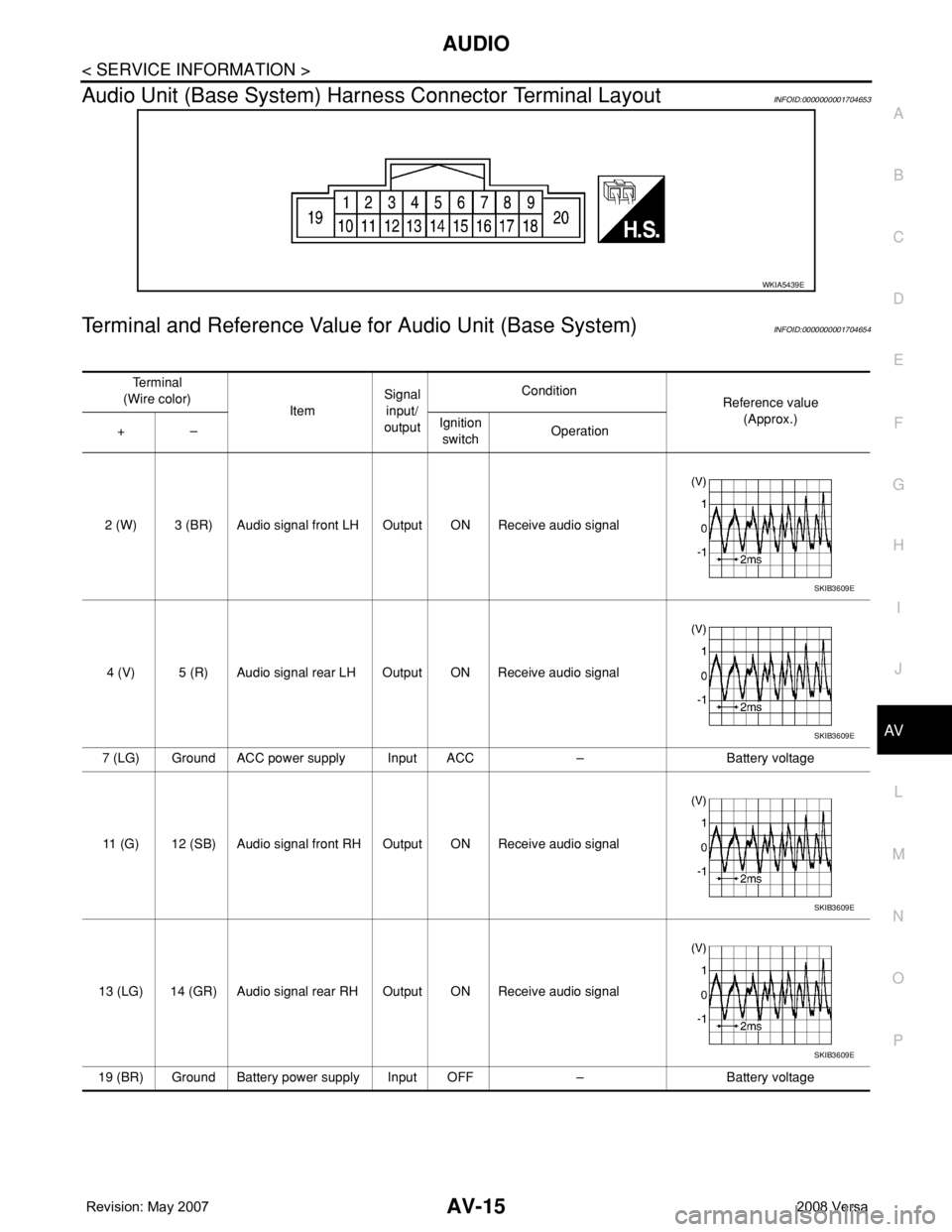
Audio Unit (Base System) Harness Connector Terminal LayoutINFOID:0000000001704653
Terminal and Reference Value for Audio Unit (Base System)INFOID:0000000001704654
WKIA5439E
Te r m i n a l
(Wire color)
ItemSignal
input/
outputCondition
Reference value
(Approx.)
+–Ignition
switchOperation
2 (W) 3 (BR) Audio signal front LH Output ON Receive audio signal
4 (V) 5 (R) Audio signal rear LH Output ON Receive audio signal
7 (LG) Ground ACC power supply Input ACC – Battery voltage
11 (G) 12 (SB) Audio signal front RH Output ON Receive audio signal
13 (LG) 14 (GR) Audio signal rear RH Output ON Receive audio signal
19 (BR) Ground Battery power supply Input OFF – Battery voltage
SKIB3609E
SKIB3609E
SKIB3609E
SKIB3609E
Page 375 of 2771
AV-16
< SERVICE INFORMATION >
AUDIO
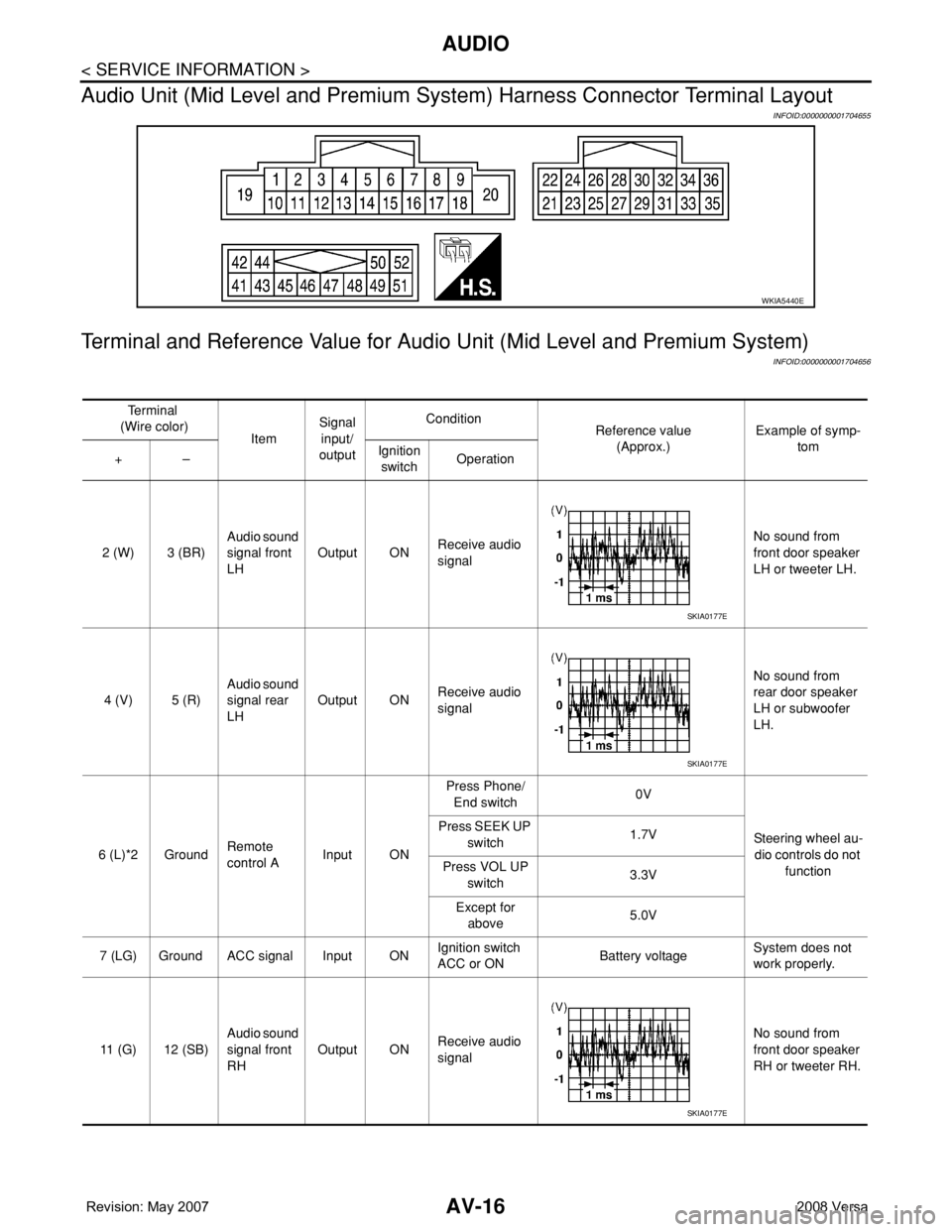
Audio Unit (Mid Level and Premium System) Harness Connector Terminal Layout
INFOID:0000000001704655
Terminal and Reference Value for Audio Unit (Mid Level and Premium System)
INFOID:0000000001704656
WKIA5440E
Te r m i n a l
(Wire color)
ItemSignal
input/
outputCondition
Reference value
(Approx.)Example of symp-
tom
+–Ignition
switchOperation
2 (W) 3 (BR)Audio sound
signal front
LHOutput ONReceive audio
signalNo sound from
front door speaker
LH or tweeter LH.
4 (V) 5 (R)Audio sound
signal rear
LHOutput ONReceive audio
signalNo sound from
rear door speaker
LH or subwoofer
LH.
6 (L)*2 GroundRemote
control AInput ONPress Phone/
End switch0V
Steering wheel au-
dio controls do not
function Press SEEK UP
switch1.7V
Press VOL UP
switch3.3V
Except for
above5.0V
7 (LG) Ground ACC signal Input ONIgnition switch
ACC or ONBattery voltageSystem does not
work properly.
11 (G) 12 (SB)Audio sound
signal front
RHOutput ONReceive audio
signalNo sound from
front door speaker
RH or tweeter RH.
SKIA0177E
SKIA0177E
SKIA0177E
Page 378 of 2771
AUDIO
AV-19
< SERVICE INFORMATION >
C
D
E
F
G
H
I
J
L
MA
B
AV
N
O
P
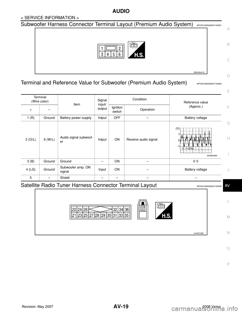
Subwoofer Harness Connector Terminal Layout (Premium Audio System)INFOID:0000000001704657
Terminal and Reference Value for Subwoofer (Premium Audio System)INFOID:0000000001704658
Satellite Radio Tuner Harness Connector Terminal LayoutINFOID:0000000001704659
WKIA5441E
Te r m i n a l
(Wire color)
ItemSignal
input/
outputCondition
Reference value
(Approx.)
+–Ignition
switchOperation
1 (R) Ground Battery power supply Intput OFF – Battery voltage
2 (O/L) 6 (W/L)Audio signal subwoof-
erIntput ON Receive audio signal
3 (B) Ground Ground – ON – 0 V
4 (LG) GroundSubwoofer amp. ON
signalInput ON – Battery voltage
5–Shield –– – –
SKIB3609E
LKIA0735E
Page 379 of 2771
AV-20
< SERVICE INFORMATION >
AUDIO
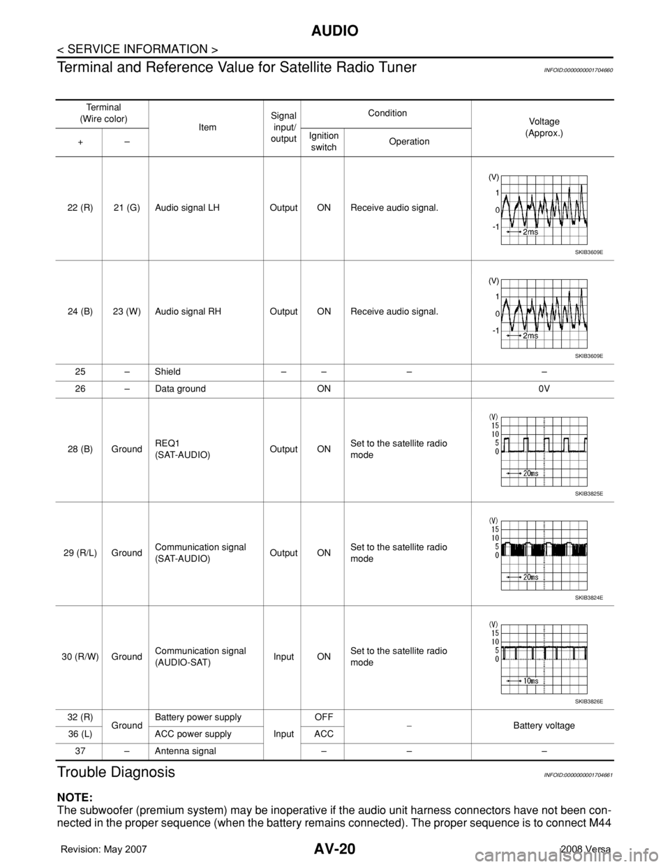
Terminal and Reference Value for Satellite Radio Tuner
INFOID:0000000001704660
Trouble DiagnosisINFOID:0000000001704661
NOTE:
The subwoofer (premium system) may be inoperative if the audio unit harness connectors have not been con-
nected in the proper sequence (when the battery remains connected). The proper sequence is to connect M44
Te r m i n a l
(Wire color)
ItemSignal
input/
outputCondition
Vol tag e
(Approx.)
+–Ignition
switchOperation
22 (R) 21 (G) Audio signal LH Output ON Receive audio signal.
24 (B) 23 (W) Audio signal RH Output ON Receive audio signal.
25 – Shield – – – –
26 – Data ground ON 0V
28 (B) GroundREQ1
(SAT-AUDIO)Output ONSet to the satellite radio
mode
29 (R/L) GroundCommunication signal
(SAT-AUDIO)Output ONSet to the satellite radio
mode
30 (R/W) GroundCommunication signal
(AUDIO-SAT)Input ONSet to the satellite radio
mode
32 (R)
GroundBattery power supply
InputOFF
−Battery voltage
36 (L) ACC power supply ACC
37 – Antenna signal – – –
SKIB3609E
SKIB3609E
SKIB3825E
SKIB3824E
SKIB3826E