2008 NISSAN TIIDA Eps
[x] Cancel search: EpsPage 813 of 2771
CL-12
< SERVICE INFORMATION >
CLUTCH PIPING
CLUTCH PIPING
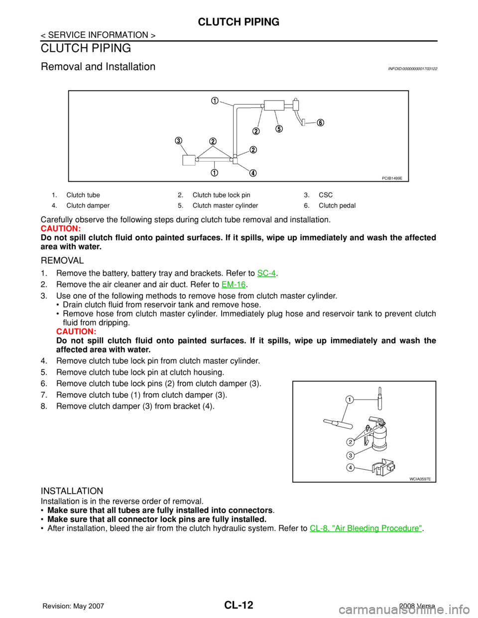
Removal and InstallationINFOID:0000000001703122
Carefully observe the following steps during clutch tube removal and installation.
CAUTION:
Do not spill clutch fluid onto painted surfaces. If it spills, wipe up immediately and wash the affected
area with water.
REMOVAL
1. Remove the battery, battery tray and brackets. Refer to SC-4.
2. Remove the air cleaner and air duct. Refer to EM-16
.
3. Use one of the following methods to remove hose from clutch master cylinder.
• Drain clutch fluid from reservoir tank and remove hose.
• Remove hose from clutch master cylinder. Immediately plug hose and reservoir tank to prevent clutch
fluid from dripping.
CAUTION:
Do not spill clutch fluid onto painted surfaces. If it spills, wipe up immediately and wash the
affected area with water.
4. Remove clutch tube lock pin from clutch master cylinder.
5. Remove clutch tube lock pin at clutch housing.
6. Remove clutch tube lock pins (2) from clutch damper (3).
7. Remove clutch tube (1) from clutch damper (3).
8. Remove clutch damper (3) from bracket (4).
INSTALLATION
Installation is in the reverse order of removal.
•Make sure that all tubes are fully installed into connectors.
•Make sure that all connector lock pins are fully installed.
• After installation, bleed the air from the clutch hydraulic system. Refer to CL-8, "
Air Bleeding Procedure".
1. Clutch tube 2. Clutch tube lock pin 3. CSC
4. Clutch damper 5. Clutch master cylinder 6. Clutch pedal
PCIB1499E
WCIA0597E
Page 816 of 2771
CLUTCH DISC, CLUTCH COVER AND FLYWHEEL
CL-15
< SERVICE INFORMATION >
D
E
F
G
H
I
J
K
L
MA
B
CL
N
O
P
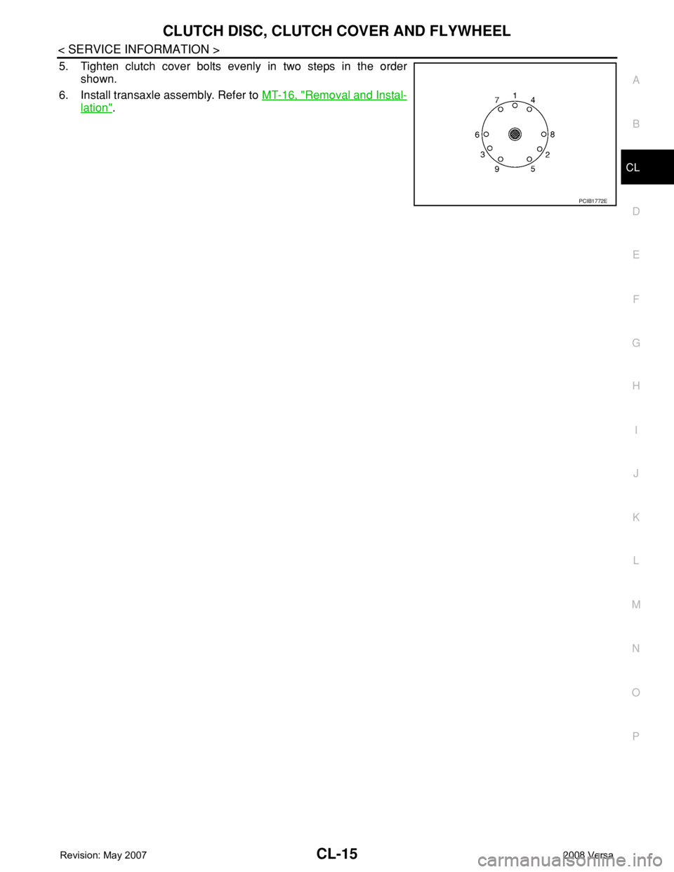
5. Tighten clutch cover bolts evenly in two steps in the order
shown.
6. Install transaxle assembly. Refer to MT-16, "
Removal and Instal-
lation".
PCIB1772E
Page 826 of 2771
ENGINE COOLANT
CO-9
< SERVICE INFORMATION >
C
D
E
F
G
H
I
J
K
L
MA
CO
N
P O
1. Install reservoir tank if removed. Refer to CO-11.
2. Install radiator drain plug.
•If water drain plug on cylinder block is removed, close and tighten it. Refer to EM-76
.
CAUTION:
Be sure to clean radiator drain plug and install with new O-ring. Refer to CO-11, "
Component".
3. Make sure that each hose clamp has been firmly tightened.
4. Remove air duct assembly. Refer to EM-16
.
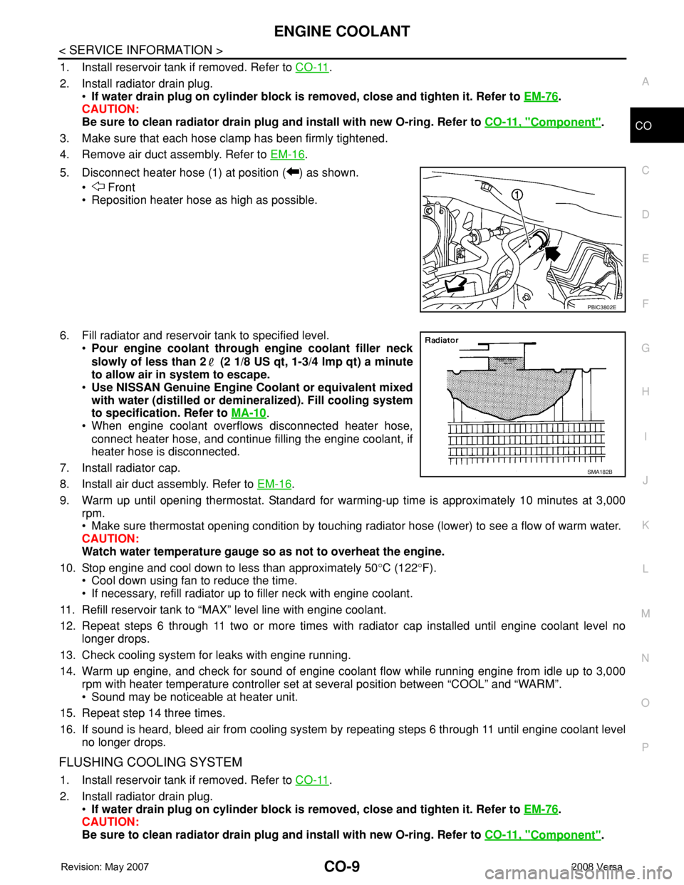
5. Disconnect heater hose (1) at position ( ) as shown.
• Front
• Reposition heater hose as high as possible.
6. Fill radiator and reservoir tank to specified level.
•Pour engine coolant through engine coolant filler neck
slowly of less than 2 (2 1/8 US qt, 1-3/4 lmp qt) a minute
to allow air in system to escape.
•Use NISSAN Genuine Engine Coolant or equivalent mixed
with water (distilled or demineralized). Fill cooling system
to specification. Refer to MA-10
.
• When engine coolant overflows disconnected heater hose,
connect heater hose, and continue filling the engine coolant, if
heater hose is disconnected.
7. Install radiator cap.
8. Install air duct assembly. Refer to EM-16
.
9. Warm up until opening thermostat. Standard for warming-up time is approximately 10 minutes at 3,000
rpm.
• Make sure thermostat opening condition by touching radiator hose (lower) to see a flow of warm water.
CAUTION:
Watch water temperature gauge so as not to overheat the engine.
10. Stop engine and cool down to less than approximately 50°C (122°F).
• Cool down using fan to reduce the time.
• If necessary, refill radiator up to filler neck with engine coolant.
11. Refill reservoir tank to “MAX” level line with engine coolant.
12. Repeat steps 6 through 11 two or more times with radiator cap installed until engine coolant level no
longer drops.
13. Check cooling system for leaks with engine running.
14. Warm up engine, and check for sound of engine coolant flow while running engine from idle up to 3,000
rpm with heater temperature controller set at several position between “COOL” and “WARM”.
• Sound may be noticeable at heater unit.
15. Repeat step 14 three times.
16. If sound is heard, bleed air from cooling system by repeating steps 6 through 11 until engine coolant level
no longer drops.
FLUSHING COOLING SYSTEM
1. Install reservoir tank if removed. Refer to CO-11.
2. Install radiator drain plug.
•If water drain plug on cylinder block is removed, close and tighten it. Refer to EM-76
.
CAUTION:
Be sure to clean radiator drain plug and install with new O-ring. Refer to CO-11, "
Component".
PBIC3802E
SMA182B
Page 827 of 2771

CO-10
< SERVICE INFORMATION >
ENGINE COOLANT
3. Fill radiator and reservoir tank with water and reinstall radiator cap.
4. Run engine and warm it up to normal operating temperature.
5. Rev engine two or three times under no-load.
6. Stop engine and wait until it cools down.
7. Drain water from the cooling system. Refer to CO-8, "
Changing Engine Coolant".
8. Repeat steps 1 through 7 until clear water begins to drain from radiator.
Page 854 of 2771
CVT FLUID
CVT-15
< SERVICE INFORMATION >
D
E
F
G
H
I
J
K
L
MA
B
CVT
N
O
P
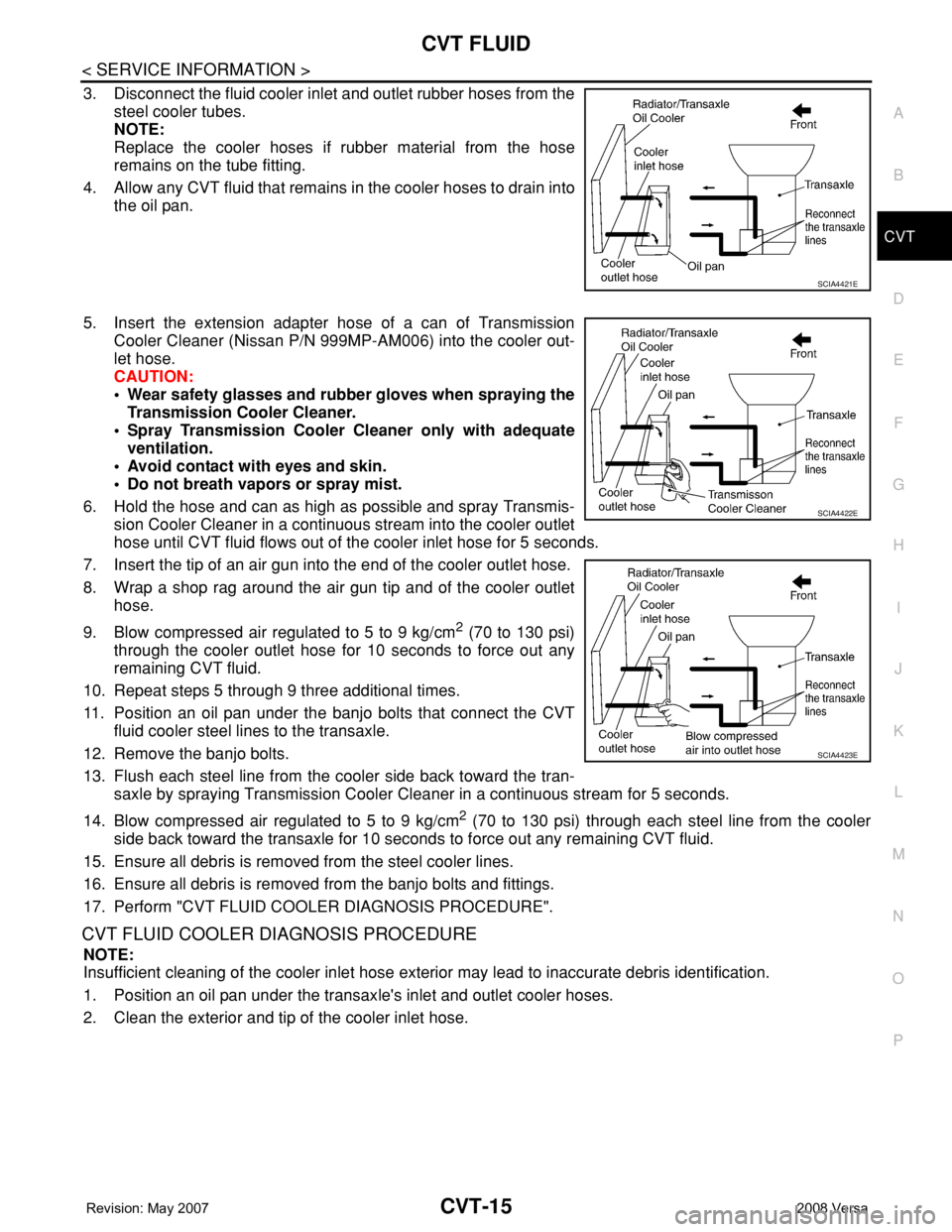
3. Disconnect the fluid cooler inlet and outlet rubber hoses from the
steel cooler tubes.
NOTE:
Replace the cooler hoses if rubber material from the hose
remains on the tube fitting.
4. Allow any CVT fluid that remains in the cooler hoses to drain into
the oil pan.
5. Insert the extension adapter hose of a can of Transmission
Cooler Cleaner (Nissan P/N 999MP-AM006) into the cooler out-
let hose.
CAUTION:
• Wear safety glasses and rubber gloves when spraying the
Transmission Cooler Cleaner.
• Spray Transmission Cooler Cleaner only with adequate
ventilation.
• Avoid contact with eyes and skin.
• Do not breath vapors or spray mist.
6. Hold the hose and can as high as possible and spray Transmis-
sion Cooler Cleaner in a continuous stream into the cooler outlet
hose until CVT fluid flows out of the cooler inlet hose for 5 seconds.
7. Insert the tip of an air gun into the end of the cooler outlet hose.
8. Wrap a shop rag around the air gun tip and of the cooler outlet
hose.
9. Blow compressed air regulated to 5 to 9 kg/cm
2 (70 to 130 psi)
through the cooler outlet hose for 10 seconds to force out any
remaining CVT fluid.
10. Repeat steps 5 through 9 three additional times.
11. Position an oil pan under the banjo bolts that connect the CVT
fluid cooler steel lines to the transaxle.
12. Remove the banjo bolts.
13. Flush each steel line from the cooler side back toward the tran-
saxle by spraying Transmission Cooler Cleaner in a continuous stream for 5 seconds.
14. Blow compressed air regulated to 5 to 9 kg/cm
2 (70 to 130 psi) through each steel line from the cooler
side back toward the transaxle for 10 seconds to force out any remaining CVT fluid.
15. Ensure all debris is removed from the steel cooler lines.
16. Ensure all debris is removed from the banjo bolts and fittings.
17. Perform "CVT FLUID COOLER DIAGNOSIS PROCEDURE".
CVT FLUID COOLER DIAGNOSIS PROCEDURE
NOTE:
Insufficient cleaning of the cooler inlet hose exterior may lead to inaccurate debris identification.
1. Position an oil pan under the transaxle's inlet and outlet cooler hoses.
2. Clean the exterior and tip of the cooler inlet hose.
SCIA4421E
SCIA4422E
SCIA4423E
Page 862 of 2771

CVT SYSTEM
CVT-23
< SERVICE INFORMATION >
D
E
F
G
H
I
J
K
L
MA
B
CVT
N
O
P
Optimize the line pressure and secondary pressure, depending on driving conditions, on the basis of the throt-
tle position, the engine speed, the primary pulley (input) revolution speed, the secondary pulley (output) revo-
lution speed, the brake signal, the PNP switch signal, the lock-up signal, the voltage, the target gear ratio, the
fluid temperature, and the fluid pressure.
FEEDBACK CONTROL
When controlling the normal fluid pressure or the selected fluid pressure, the secondary pressure can be set
more accurately by using the fluid pressure sensor to detect the secondary pressure and controlling the feed-
back.
Shift ControlINFOID:0000000001703443
In order to select the gear ratio which can obtain the driving force in accordance with driver's intention and the
vehicle condition, TCM monitors the driving conditions, such as the vehicle speed and the throttle position and
selects the optimum gear ratio, and determines the gear change steps to the gear ratio. Then send the com-
mand to the step motor, and control the flow-in/flow-out of line pressure from the primary pulley to determine
the position of the moving-pulley and control the gear ratio.
NOTE:
The gear ratio is set for every position separately.
“D” POSITION
Shifting over all the ranges of gear ratios from the lowest to the high-
est.
OVERDRIVE-OFF MODE
Use this position for the improved engine braking.
“L” POSITION
SCIA7958E
SCIA1953E
Page 877 of 2771
CVT-38
< SERVICE INFORMATION >
TROUBLE DIAGNOSIS
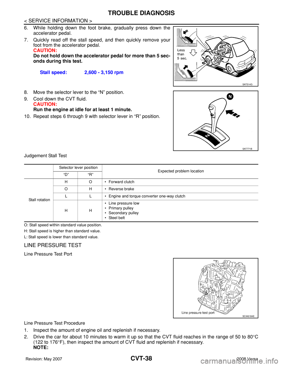
6. While holding down the foot brake, gradually press down the
accelerator pedal.
7. Quickly read off the stall speed, and then quickly remove your
foot from the accelerator pedal.
CAUTION:
Do not hold down the accelerator pedal for more than 5 sec-
onds during this test.
8. Move the selector lever to the “N” position.
9. Cool down the CVT fluid.
CAUTION:
Run the engine at idle for at least 1 minute.
10. Repeat steps 6 through 9 with selector lever in “R” position.
Judgement Stall Test
O: Stall speed within standard value position.
H: Stall speed is higher than standard value.
L: Stall speed is lower than standard value.
LINE PRESSURE TEST
Line Pressure Test Port
Line Pressure Test Procedure
1. Inspect the amount of engine oil and replenish if necessary.
2. Drive the car for about 10 minutes to warm it up so that the CVT fluid reaches in the range of 50 to 80°C
(122 to 176°F), then inspect the amount of CVT fluid and replenish if necessary.
NOTE:Stall speed: 2,600 - 3,150 rpm
SAT514G
SAT771B
Selector lever position
Expected problem location
“D” “R”
Stall rotation HO•Forward clutch
O H • Reverse brake
L L • Engine and torque converter one-way clutch
HH• Line pressure low
• Primary pulley
• Secondary pulley
• Steel belt
SCIA6184E
Page 881 of 2771
CVT-42
< SERVICE INFORMATION >
TROUBLE DIAGNOSIS
YES >> GO TO 2.
NO >> Stop “Road Test”. Mark the box on the CVT-30, "
How to Perform Trouble Diagnosis for Quick and
Accurate Repair" . Go to CVT-153, "Engine Cannot Be Started in "P" and "N" Position" .
2.CHECK STARTING THE ENGINE
1. Turn ignition switch ON.
2. Move selector lever to “D”, “L” or “R” position.
3. Turn ignition switch START.
Is engine started?
YES >> Stop “Road Test”. Mark the box on the CVT-30, "How to Perform Trouble Diagnosis for Quick and
Accurate Repair" . Go to CVT-153, "Engine Cannot Be Started in "P" and "N" Position" .
NO >> GO TO 3.
3.CHECK “P” POSITION FUNCTION
1. Move selector lever to “P” position.
2. Turn ignition switch OFF.
3. Release parking brake.
4. Push vehicle forward or backward.
5. Apply parking brake.
Does vehicle move when it is pushed forward or backward?
YES >> Mark the box CVT-153, "In "P" Position, Vehicle Moves Forward or Backward When Pushed" on
the CVT-30, "
How to Perform Trouble Diagnosis for Quick and Accurate Repair" . Continue “Road
Te s t ” .
NO >> GO TO 4.
4.CHECK “N” POSITION FUNCTION
1. Start engine.
2. Move selector lever to “N” position.
3. Release parking brake.
Does vehicle move forward or backward?
YES >> Mark the box CVT-154, "In "N" Position, Vehicle Moves" on the CVT-30, "How to Perform Trouble
Diagnosis for Quick and Accurate Repair" . Continue “Road Test”.
NO >> GO TO 5.
5.CHECK SHIFT SHOCK
1. Apply foot brake.
2. Move selector lever to “R” position.
Is there large shock when changing from
“N” to “R” position?
YES >> Mark the box CVT-154, "Large Shock "N" → "R" Position" on the CVT-30, "How to Perform Trou-
ble Diagnosis for Quick and Accurate Repair" . Continue “Road Test”.
NO >> GO TO 6.
6.CHECK “R” POSITION FUNCTION
Release foot brake for several seconds.
Does vehicle creep backward when foot brake is released?
YES >> GO TO 7.
NO >> Mark the box CVT-155, "
Vehicle Does Not Creep Backward in "R" Position" on the CVT-30, "How
to Perform Trouble Diagnosis for Quick and Accurate Repair" . Continue “Road Test”.
7.CHECK “D”, “L” POSITIONS FUNCTION
Move selector lever to “D” and “L” positions and check if vehicle creeps forward.
Does vehicle creep forward in all positions?
YES >> Go to CVT-43, "Cruise Test" .
NO >> Stop “Road Test”. Mark the box on the CVT-30, "
How to Perform Trouble Diagnosis for Quick and
Accurate Repair" . Go to CVT-156, "Vehicle Does Not Creep Forward in "D" or "L" Position" .