2008 NISSAN TIIDA Eps
[x] Cancel search: EpsPage 28 of 2771
AT-16
< SERVICE INFORMATION >
A/T FLUID
5. Run engine at idle speed for 5 minutes.
6. Check A/T fluid level and condition. Refer to MA-22, "
Checking A/T Fluid".
A/T Fluid Cooler CleaningINFOID:0000000001703160
Whenever the A/T is repaired, overhauled, or replaced, the A/T fluid cooler mounted in the radiator must be
inspected and cleaned.
Metal debris and friction material, if present, can become trapped in the A/T fluid cooler. This debris can con-
taminate the newly serviced A/T or, in severe cases, can block or restrict the flow of A/T fluid. In either case,
malfunction of the newly serviced A/T may result.
Debris, if present, may build up as A/T fluid enters the cooler inlet. It will be necessary to back flush the cooler
through the cooler outlet in order to flush out any built up debris.
A/T FLUID COOLER CLEANING PROCEDURE
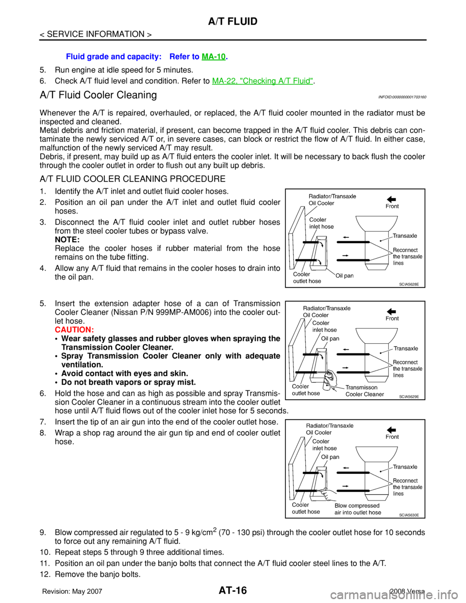
1. Identify the A/T inlet and outlet fluid cooler hoses.
2. Position an oil pan under the A/T inlet and outlet fluid cooler
hoses.
3. Disconnect the A/T fluid cooler inlet and outlet rubber hoses
from the steel cooler tubes or bypass valve.
NOTE:
Replace the cooler hoses if rubber material from the hose
remains on the tube fitting.
4. Allow any A/T fluid that remains in the cooler hoses to drain into
the oil pan.
5. Insert the extension adapter hose of a can of Transmission
Cooler Cleaner (Nissan P/N 999MP-AM006) into the cooler out-
let hose.
CAUTION:
• Wear safety glasses and rubber gloves when spraying the
Transmission Cooler Cleaner.
• Spray Transmission Cooler Cleaner only with adequate
ventilation.
• Avoid contact with eyes and skin.
• Do not breath vapors or spray mist.
6. Hold the hose and can as high as possible and spray Transmis-
sion Cooler Cleaner in a continuous stream into the cooler outlet
hose until A/T fluid flows out of the cooler inlet hose for 5 seconds.
7. Insert the tip of an air gun into the end of the cooler outlet hose.
8. Wrap a shop rag around the air gun tip and end of cooler outlet
hose.
9. Blow compressed air regulated to 5 - 9 kg/cm
2 (70 - 130 psi) through the cooler outlet hose for 10 seconds
to force out any remaining A/T fluid.
10. Repeat steps 5 through 9 three additional times.
11. Position an oil pan under the banjo bolts that connect the A/T fluid cooler steel lines to the A/T.
12. Remove the banjo bolts.Fluid grade and capacity: Refer to MA-10
.
SCIA5628E
SCIA5629E
SCIA5630E
Page 61 of 2771
TROUBLE DIAGNOSIS
AT-49
< SERVICE INFORMATION >
D
E
F
G
H
I
J
K
L
MA
B
AT
N
O
P
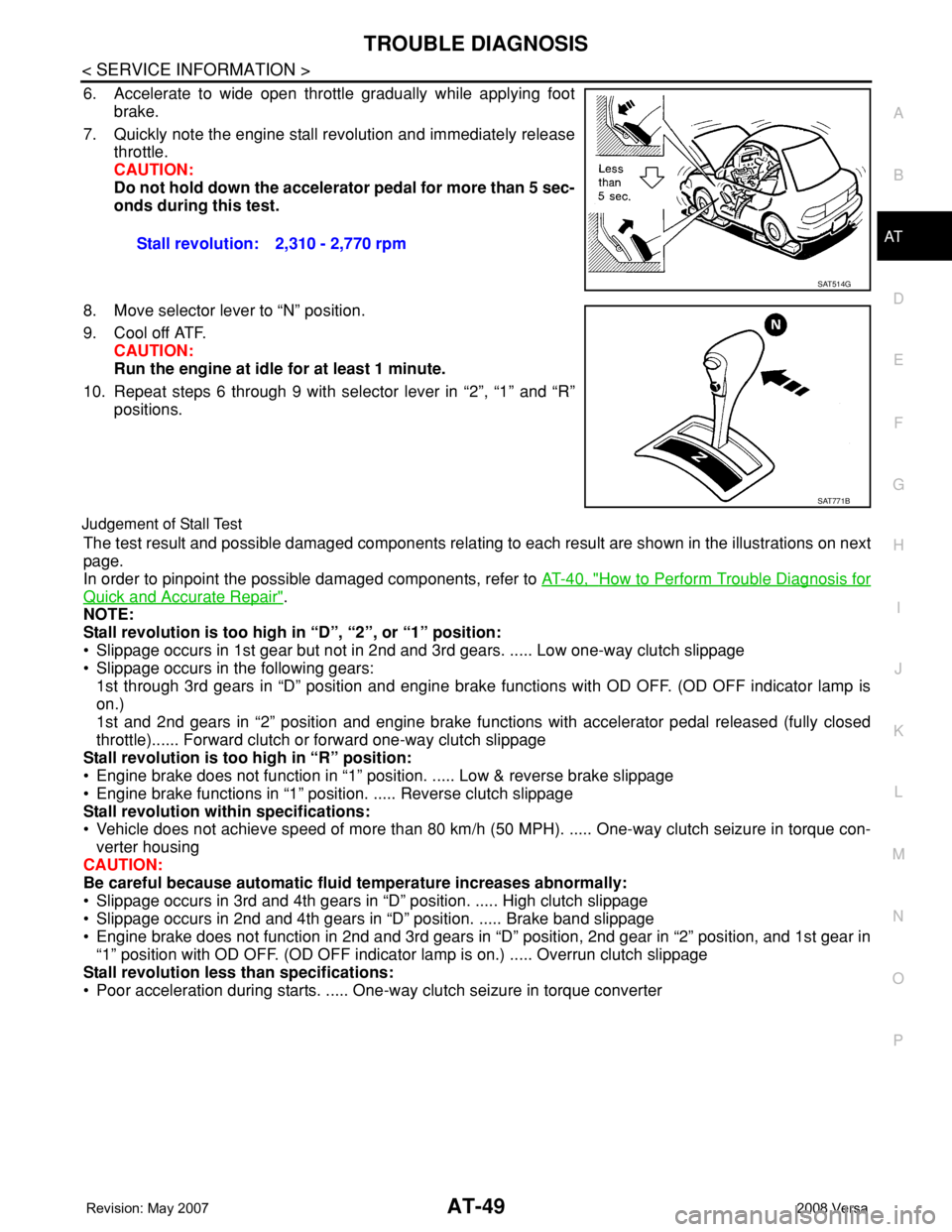
6. Accelerate to wide open throttle gradually while applying foot
brake.
7. Quickly note the engine stall revolution and immediately release
throttle.
CAUTION:
Do not hold down the accelerator pedal for more than 5 sec-
onds during this test.
8. Move selector lever to “N” position.
9. Cool off ATF.
CAUTION:
Run the engine at idle for at least 1 minute.
10. Repeat steps 6 through 9 with selector lever in “2”, “1” and “R”
positions.
Judgement of Stall Test
The test result and possible damaged components relating to each result are shown in the illustrations on next
page.
In order to pinpoint the possible damaged components, refer to AT-40, "
How to Perform Trouble Diagnosis for
Quick and Accurate Repair".
NOTE:
Stall revolution is too high in “D”, “2”, or “1” position:
• Slippage occurs in 1st gear but not in 2nd and 3rd gears. ..... Low one-way clutch slippage
• Slippage occurs in the following gears:
1st through 3rd gears in “D” position and engine brake functions with OD OFF. (OD OFF indicator lamp is
on.)
1st and 2nd gears in “2” position and engine brake functions with accelerator pedal released (fully closed
throttle)...... Forward clutch or forward one-way clutch slippage
Stall revolution is too high in “R” position:
• Engine brake does not function in “1” position. ..... Low & reverse brake slippage
• Engine brake functions in “1” position. ..... Reverse clutch slippage
Stall revolution within specifications:
• Vehicle does not achieve speed of more than 80 km/h (50 MPH). ..... One-way clutch seizure in torque con-
verter housing
CAUTION:
Be careful because automatic fluid temperature increases abnormally:
• Slippage occurs in 3rd and 4th gears in “D” position. ..... High clutch slippage
• Slippage occurs in 2nd and 4th gears in “D” position. ..... Brake band slippage
• Engine brake does not function in 2nd and 3rd gears in “D” position, 2nd gear in “2” position, and 1st gear in
“1” position with OD OFF. (OD OFF indicator lamp is on.) ..... Overrun clutch slippage
Stall revolution less than specifications:
• Poor acceleration during starts. ..... One-way clutch seizure in torque converter Stall revolution: 2,310 - 2,770 rpm
SAT514G
SAT771B
Page 67 of 2771
TROUBLE DIAGNOSIS
AT-55
< SERVICE INFORMATION >
D
E
F
G
H
I
J
K
L
MA
B
AT
N
O
P
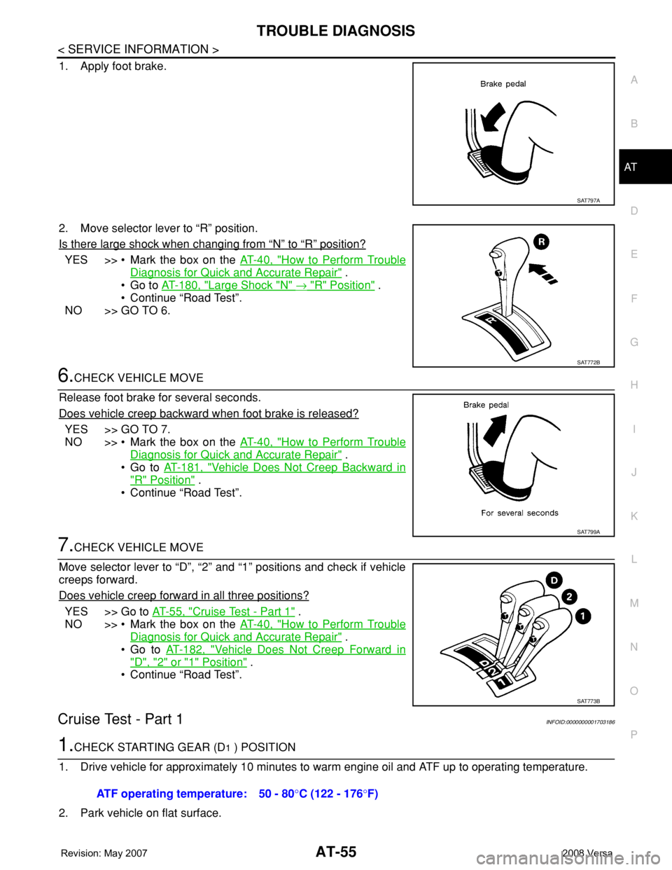
1. Apply foot brake.
2. Move selector lever to “R” position.
Is there large shock when changing from
“N” to “R” position?
YES >> • Mark the box on the AT-40, "How to Perform Trouble
Diagnosis for Quick and Accurate Repair" .
•Go to AT-180, "
Large Shock "N" → "R" Position" .
• Continue “Road Test”.
NO >> GO TO 6.
6.CHECK VEHICLE MOVE
Release foot brake for several seconds.
Does vehicle creep backward when foot brake is released?
YES >> GO TO 7.
NO >> • Mark the box on the AT-40, "
How to Perform Trouble
Diagnosis for Quick and Accurate Repair" .
•Go to AT-181, "
Vehicle Does Not Creep Backward in
"R" Position" .
• Continue “Road Test”.
7.CHECK VEHICLE MOVE
Move selector lever to “D”, “2” and “1” positions and check if vehicle
creeps forward.
Does vehicle creep forward in all three positions?
YES >> Go to AT-55, "Cruise Test - Part 1" .
NO >> • Mark the box on the AT-40, "
How to Perform Trouble
Diagnosis for Quick and Accurate Repair" .
•Go to AT-182, "
Vehicle Does Not Creep Forward in
"D", "2" or "1" Position" .
• Continue “Road Test”.
Cruise Test - Part 1INFOID:0000000001703186
1.CHECK STARTING GEAR (D1 ) POSITION
1. Drive vehicle for approximately 10 minutes to warm engine oil and ATF up to operating temperature.
2. Park vehicle on flat surface.
SAT797A
SAT772B
SAT799A
SAT773B
ATF operating temperature: 50 - 80°C (122 - 176°F)
Page 393 of 2771
AV-34
< SERVICE INFORMATION >
AUDIO
Sound Is Not Heard from Subwoofer (Premium System)
INFOID:0000000001704673
1.CHECK FUSE
Check that the following fuse is not blown.
OK or NG
OK >> GO TO 2.
NG >> If fuse is blown, be sure to eliminate cause of blown fuse before installing new fuse. Refer to PG-
3 .
2.EQ SETTING CHECK
1. Ensure that subwoofer amp. connector B29 and audio unit harness connectors M43, M44 and M45 are
securely connected.
2. Turn the ignition switch to the ACC position.
3. Press the "AUDIO", "AUX", and "TUNE DOWN" switches simultaneously, the current EQ Setting will be
displayed.
Is "Woofer On" displayed?
YES >> GO TO 3.
NO >> Disconnect all audio unit harness connectors and wait for 2 minutes in order to reset the audio
unit. Reconnect audio unit connectors M44 and M45 first followed by M43 last. Repeat Steps 1
through 3 to confirm that "Woofer On" is now displayed.
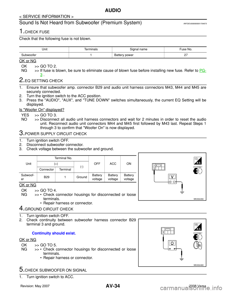
3.POWER SUPPLY CIRCUIT CHECK
1. Turn ignition switch OFF.
2. Disconnect subwoofer connector.
3. Check voltage between the subwoofer and ground.
OK or NG
OK >> GO TO 4.
NG >> • Check connector housings for disconnected or loose
terminals.
• Repair harness or connector.
4.GROUND CIRCUIT CHECK
1. Turn ignition switch OFF.
2. Check continuity between subwoofer harness connector B29
terminal 3 and ground.
OK or NG
OK >> GO TO 5.
NG >> • Check connector housings for disconnected or loose
terminals.
• Repair harness or connector.
5.CHECK SUBWOOFER ON SIGNAL
1. Turn ignition switch to ACC.
Unit Terminals Signal name Fuse No.
Subwoofer 1 Battery power 27
UnitTe r m i n a l N o .
OFF ACC ON (+)
(-)
Connector Terminal
Subwoof-
erB29 1 GroundBattery
voltageBattery
voltageBattery
voltage
WKIA5445E
Continuity should exist.
WKIA5446E
Page 657 of 2771
NATS (NISSAN ANTI-THEFT SYSTEM)
BL-223
< SERVICE INFORMATION >
C
D
E
F
G
H
J
K
L
MA
B
BL
N
O
P
OK or NG
OK >> BCM is malfunctioning.
• Replace BCM. Refer to BCS-18, "
Removal and Instal-
lation of BCM" .
• Perform initialization with CONSULT-III
• For initialization, refer to “CONSULT-III Operation
Manual NATS”
NG >> Check the following.
• Harness for open or short between combination meter (security) and BCM
• Indicator lamp condition
Diagnosis Procedure 5INFOID:0000000001704116
Self-diagnostic results:
“LOCK MODE” displayed on CONSULT-III screen
1.CONFIRM SELF-DIAGNOSTIC RESULTS
Confirm SELF-DIAGNOSTIC RESULTS “LOCK MODE” is displayed on CONSULT-III screen.
Is
“LOCK MODE” displayed?
Yes >> GO TO 2.
No >> GO TO BL-217, "
Trouble Diagnosis" .
2.ESCAPE FROM LOCK MODE
1. Turn ignition switch OFF.
2. Turn ignition switch ON with registered key. (Do not start engine.) Wait 5 seconds.
3. Return the key to OFF position. Wait 5 seconds.
4. Repeat steps 2 and 3 twice (total of three cycles).
5. Start the engine.
Does engine start?
Yes >> System is OK (Now system is escaped from “LOCK MODE”).
No >> GO TO 3.
3.PERFORM INITIALIZATION WITH CONSULT-III
Perform initialization with CONSULT-III.
For initialization, refer to “CONSULT-III Operation Manual NATS”.
NOTE:
If the initialization is not completed or malfunctions, CONSULT-III shows the message on the screen.
Can the system be initialized?
Yes >> System is OK.
No >> GO TO 4.
4.PERFORM INITIALIZATION WITH CONSULT-III AGAIN
1. Replace BCM.
2. Perform initialization with CONSULT-III.
For initialization, refer to “CONSULT-III Operation Manual NATS”.
NOTE:
If the initialization is not completed or malfunctions, CONSULT-III shows the message on the screen.
Can the system be initialized?
Yes >> System is OK. (BCM is malfunctioning.)
No >> ECM is malfunctioning.
• Replace ECM.
• Perform initialization with CONSULT-III
• For initialization, refer to “CONSULT-III Operation Manual NATS”
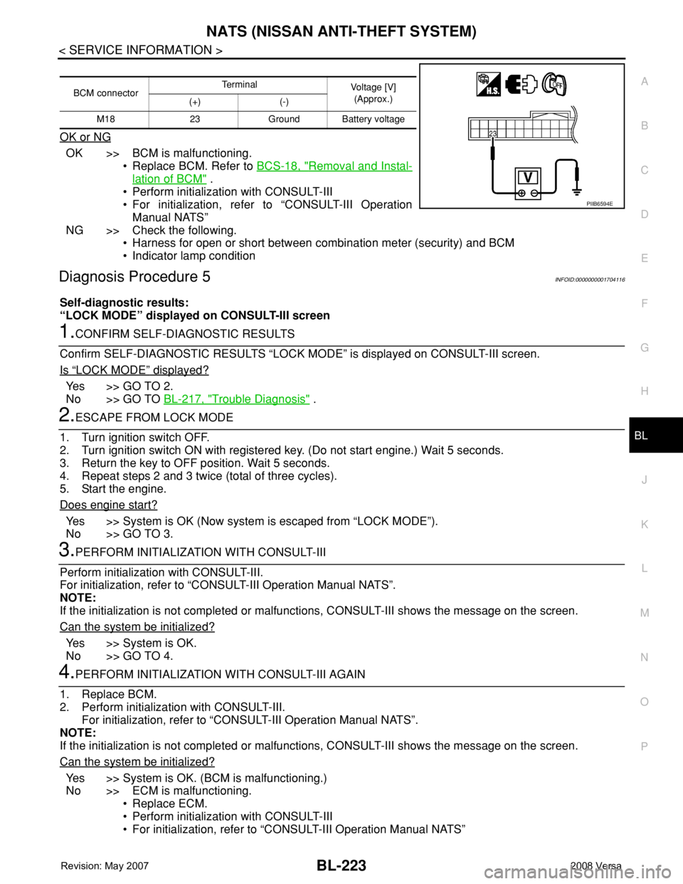
BCM connectorTerminal
Voltage [V]
(Approx.)
(+) (-)
M18 23 Ground Battery voltage
PIIB6594E
Page 740 of 2771

BRAKE FLUID
BR-9
< SERVICE INFORMATION >
C
D
E
G
H
I
J
K
L
MA
B
BR
N
O
P
3. With brake pedal depressed, loosen bleed valve to let the air out, and then tighten it immediately.
4. Repeat steps 2, 3 until no more air comes out.
5. Tighten bleed valve to specified torque. Refer to BR-23, "
Component" (front disc brake), BR-29, "Compo-
nent" (rear drum brake).
6. Following the steps 1 to 5 above, with master cylinder reservoir tank filled at least half way, bleed air from
the rear right, front left, rear left, and front right brake, in that order.
Page 759 of 2771
BR-28
< SERVICE INFORMATION >
FRONT DISC BRAKE
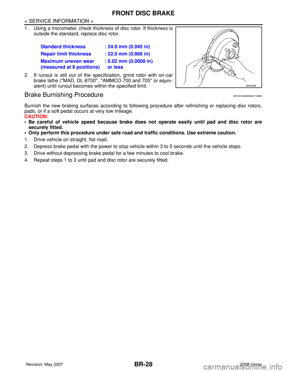
1. Using a micrometer, check thickness of disc rotor. If thickness is
outside the standard, replace disc rotor.
2. If runout is still out of the specification, grind rotor with on-car
brake lathe (″MAD, DL-8700″, ″AMMCO 700 and 705″ or equiv-
alent) until runout becomes within the specified limit.
Brake Burnishing ProcedureINFOID:0000000001703801
Burnish the new braking surfaces according to following procedure after refinishing or replacing disc rotors,
pads, or if a soft pedal occurs at very low mileage.
CAUTION:
• Be careful of vehicle speed because brake does not operate easily until pad and disc rotor are
securely fitted.
• Only perform this procedure under safe road and traffic conditions. Use extreme caution.
1. Drive vehicle on straight, flat road.
2. Depress brake pedal with the power to stop vehicle within 3 to 5 seconds until the vehicle stops.
3. Drive without depressing brake pedal for a few minutes to cool brake.
4. Repeat steps 1 to 3 until pad and disc rotor are securely fitted.Standard thickness : 24.0 mm (0.945 in)
Repair limit thickness : 22.0 mm (0.866 in)
Maximum uneven wear
(measured at 8 positions): 0.02 mm (0.0008 in)
or less
SBR020B
Page 809 of 2771
CL-8
< SERVICE INFORMATION >
CLUTCH FLUID
CLUTCH FLUID
Air Bleeding ProcedureINFOID:0000000001703119
CAUTION:
Do not spill clutch fluid onto painted surfaces. If it spills, wipe up immediately and wash the affected
area with water.
NOTE:
• Do not use a vacuum assist or any other type of power bleeder on this system. Use of a vacuum assist or
power bleeder will not purge all the air from the system.
• Carefully monitor fluid level in reservoir tank during bleeding operation.
1. Fill master cylinder reservoir tank with new clutch fluid.
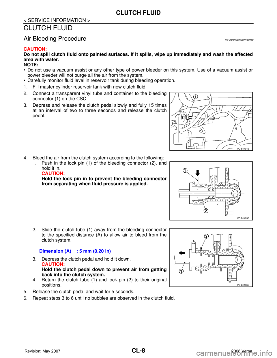
2. Connect a transparent vinyl tube and container to the bleeding
connector (1) on the CSC.
3. Depress and release the clutch pedal slowly and fully 15 times
at an interval of two to three seconds and release the clutch
pedal.
4. Bleed the air from the clutch system according to the following:
1. Push in the lock pin (1) of the bleeding connector (2), and
hold it in.
CAUTION:
Hold the lock pin in to prevent the bleeding connector
from separating when fluid pressure is applied.
2. Slide the clutch tube (1) away from the bleeding connector
to the specified distance (A) to allow air to bleed from the
clutch system.
3. Depress the clutch pedal and hold it down.
CAUTION:
Hold the clutch pedal down to prevent air from getting
back into the clutch system.
4. Return the clutch tube (1) and lock pin (2) to their original
positions.
5. Release the clutch pedal and wait for 5 seconds.
6. Repeat steps 3 to 6 until no bubbles are observed in the clutch fluid.
PCIB1494E
PCIB1495E
Dimension (A) : 5 mm (0.20 in)
PCIB1496E