Page 1661 of 2771

EI-38
< ON-VEHICLE REPAIR >
BODY SIDE TRIM
Sedan Models
Removal and InstallationINFOID:0000000001704236
WARNING:
Do not reuse center pillar upper garnish if removed.
CAUTION:
• Insert a suitable tool between panel on vehicle and clips (as
indicated with arrow) to release clips.
• Use a suitable tool when removing metal clips from garnishes.
• Be careful not to damage the body while prying to release
clips.
• Make sure clips are properly aligned in panel holes on body
when installing, then press them in completely.
• When releasing molded-in pawls or resin clips, follow the
steps below to prevent garnish or clip damage.
FRONT PILLAR GARNISH
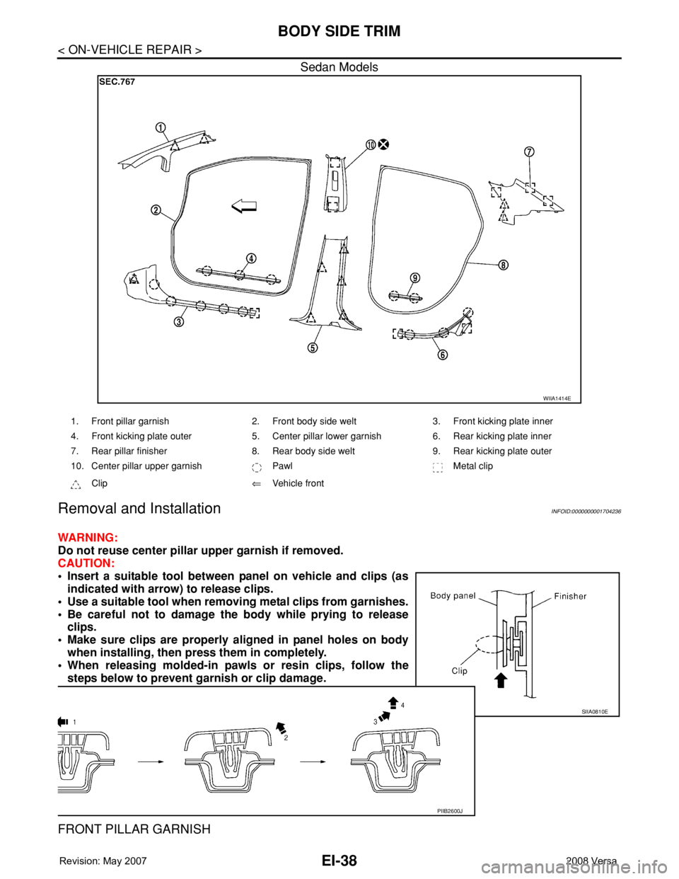
WIIA1414E
1. Front pillar garnish 2. Front body side welt 3. Front kicking plate inner
4. Front kicking plate outer 5. Center pillar lower garnish 6. Rear kicking plate inner
7. Rear pillar finisher 8. Rear body side welt 9. Rear kicking plate outer
10. Center pillar upper garnish Pawl Metal clip
Clip⇐Vehicle front
SIIA0810E
PIIB2600J
Page 1681 of 2771

EM-4
< SERVICE INFORMATION >
PRECAUTIONS
2. Use the Intelligent Key or mechanical key to turn the ignition switch to the ″ACC″ position. At this time, the
steering lock will be released.
3. Disconnect both battery cables. The steering lock will remain released and the steering wheel can be
rotated.
4. Perform the necessary repair operation.
5. When the repair work is completed, return the ignition switch to the ″LOCK″ position before connecting
the battery cables. (At this time, the steering lock mechanism will engage.)
6. Perform a self-diagnosis check of all control units using CONSULT-III.
Precaution for Drain CoolantINFOID:0000000001702463
• Drain coolant when engine is cooled.
Precaution for Disconnecting Fuel PipingINFOID:0000000001702464
• Before starting work, make sure no fire or spark producing items are in the work area.
• Release fuel pressure before disassembly.
• After disconnecting pipes, plug openings to stop fuel leakage.
Precaution for Removal and DisassemblyINFOID:0000000001702465
• When instructed to use special service tools, use the specified tools. Always be careful to work safely, avoid
forceful or uninstructed operations.
• Exercise maximum care to avoid damage to mating or sliding surfaces.
• Cover openings of engine system with tape or the equivalent, if necessary, to seal out foreign materials.
• Mark and arrange disassembly parts in an organized way for easy troubleshooting and assembly.
• When loosening nuts and bolts, as a basic rule, start with the one furthest outside, then the one diagonally
opposite, and so on. If the order of loosening is specified, do exactly as specified. Power tools may be used
where noted in the step.
Precaution for Inspection, Repair and ReplacementINFOID:0000000001702466
• Before repairing or replacing, thoroughly inspect parts. Inspect new replacement parts in the same way, and
replace if necessary.
Precaution for Assembly and InstallationINFOID:0000000001702467
• Use torque wrench to tighten bolts or nuts to specification.
• When tightening nuts and bolts, as a basic rule, equally tighten in several different steps starting with the
ones in center, then ones on inside and outside diagonally in this order. If the order of tightening is specified,
do exactly as specified.
• Replace with new gasket, packing, oil seal or O-ring.
• Thoroughly wash, clean, and air-blow each part. Carefully check oil or coolant passages for any restriction
and blockage.
• Avoid damaging sliding or mating surfaces. Completely remove foreign materials such as cloth lint or dust.
Before assembly, oil sliding surfaces well.
• Release air within route after draining coolant.
• Before starting engine, apply fuel pressure to fuel lines with turning ignition switch ON (with engine stopped).
Then make sure that there are no leaks at fuel line connections.
• After repairing, start engine and increase engine speed to check coolant, fuel, oil, and exhaust systems for
leakage.
Parts Requiring Angular TighteningINFOID:0000000001702468
• Use an angle wrench for the final tightening of the following engine parts:
- Cylinder head bolts
- Camshaft sprocket (INT)
- Main bearing cap bolts
- Connecting rod cap nuts
- Crankshaft pulley bolt (No angle wrench is required as the bolt flange is provided with notches for angular
tightening)
Page 1709 of 2771
EM-32
< SERVICE INFORMATION >
IGNITION COIL, SPARK PLUG AND ROCKER COVER
2. Install rocker cover.
• Tighten bolts in two steps separately in numerical order as
shown.
• Engine front
CAUTION:
Check if rocker cover gasket is not dropped from the instal-
lation groove of rocker cover.
3. Install spark plug using suitable tool.
CAUTION:
Never drop or shock it.
4. Install ignition coil.
CAUTION:
• Handle it carefully and avoid impacts.
• Never disassemble.
5. Install intake manifold. Refer to EM-18
. 1st step : 1.96 N·m (0.20 kg-m, 17 in-lb)
2nd step : 8.33 N·m (0.85 kg-m, 73 in-lb)
PBIC3151J
Plug type : Iridium tipped
Make : DENSO
Part number : FXE20HR11
Gap (nominal) : 1.1 mm (0.043 in)
PBIC3871E
Page 1723 of 2771
EM-46
< SERVICE INFORMATION >
TIMING CHAIN
18. Secure crankshaft pulley (1) using Tool (A).
19. Apply new engine oil to thread and seat surfaces of crankshaft
pulley bolt.
20. Tighten crankshaft pulley bolt in three steps.
21. Put a paint mark (B) on crankshaft pulley (2), matching with any
one of six easy to recognize angle marks (A) on crankshaft pul-
ley bolt flange (1).
22. Turn another 60 degrees clockwise (angle tightening) using
Tool.
• Check the tightening angle with movement of one angle mark.
23. Make sure that crankshaft rotates clockwise smoothly.
24. Installation of the remaining components is in the reverse order of removal.Tool Number (A) : KV10109300 ( — )
Step 1 : 68.6 N·m (7.0 kg-m, 51 ft-lb)
Step 2 : 0 N·m (0 kg-m, 0 ft-lb)
Step 3 : 29.4 N·m (3.0 kg-m, 22 ft-lb)
PBIC3961E
Tool number : KV10112100 (BT-8653-A)
PBIC3963E
Page 1730 of 2771

CAMSHAFT
EM-53
< SERVICE INFORMATION >
C
D
E
F
G
H
I
J
K
L
MA
EM
N
P O
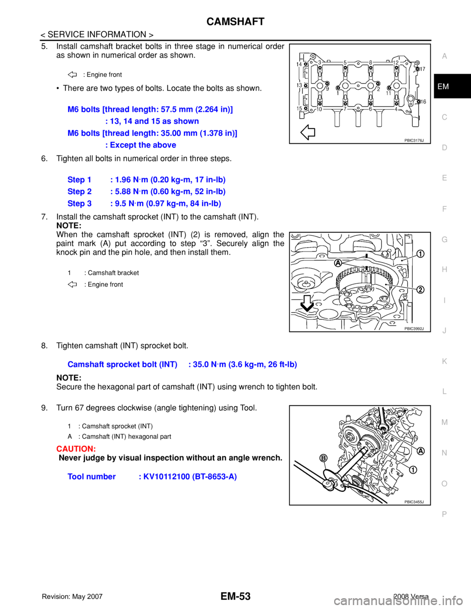
5. Install camshaft bracket bolts in three stage in numerical order
as shown in numerical order as shown.
• There are two types of bolts. Locate the bolts as shown.
6. Tighten all bolts in numerical order in three steps.
7. Install the camshaft sprocket (INT) to the camshaft (INT).
NOTE:
When the camshaft sprocket (INT) (2) is removed, align the
paint mark (A) put according to step “3”. Securely align the
knock pin and the pin hole, and then install them.
8. Tighten camshaft (INT) sprocket bolt.
NOTE:
Secure the hexagonal part of camshaft (INT) using wrench to tighten bolt.
9. Turn 67 degrees clockwise (angle tightening) using Tool.
CAUTION:
Never judge by visual inspection without an angle wrench.
: Engine front
M6 bolts [thread length: 57.5 mm (2.264 in)]
: 13, 14 and 15 as shown
M6 bolts [thread length: 35.00 mm (1.378 in)]
: Except the above
Step 1 : 1.96 N·m (0.20 kg-m, 17 in-lb)
Step 2 : 5.88 N·m (0.60 kg-m, 52 in-lb)
Step 3 : 9.5 N·m (0.97 kg-m, 84 in-lb)
1 : Camshaft bracket
: Engine front
PBIC3176J
PBIC3992J
Camshaft sprocket bolt (INT) : 35.0 N·m (3.6 kg-m, 26 ft-lb)
1 : Camshaft sprocket (INT)
A : Camshaft (INT) hexagonal part
Tool number : KV10112100 (BT-8653-A)
PBIC3455J
Page 1735 of 2771
EM-58
< SERVICE INFORMATION >
CAMSHAFT
• Thickness of new valve lifter (B) can be identified by stamp
mark (A) on the reverse side (inside the cylinder).
Stamp mark “302” indicates 3.02 mm (0.1189 in) in thickness.
NOTE:
Available thickness of valve lifter: 26 sizes range 3.00 to 3.50 mm (0.1181 to 0.1378 in) in steps of 0.02
mm (0.0008 in) (when manufactured at factory). Refer to EM-104, "
Standard and Limit".
5. Install the selected valve lifter.
6. Install camshaft. Refer to EM-47, "
Removal and Installation".
7. Install timing chain and related parts. Refer to EM-37
.
8. Manually rotate crankshaft pulley a few rotations.
9. Make sure that the valve clearances is within the standard.
10. Installation of the remaining components is in the reverse order of removal.Intake : 0.30 mm (0.012 in)
Exhaust : 0.33 mm (0.013 in)
PBIC3196J
Page 1739 of 2771

EM-62
< SERVICE INFORMATION >
CYLINDER HEAD
CYLINDER HEAD
On-Vehicle ServiceINFOID:0000000001702501
CHECKING COMPRESSION PRESSURE
1. Warm up engine thoroughly. Then, stop it.
2. Release fuel pressure. Refer to EC-78, "
Fuel Pressure Check".
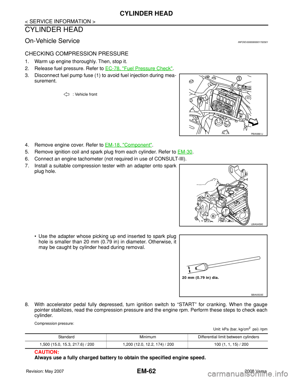
3. Disconnect fuel pump fuse (1) to avoid fuel injection during mea-
surement.
4. Remove engine cover. Refer to EM-18, "
Component".
5. Remove ignition coil and spark plug from each cylinder. Refer to EM-30
.
6. Connect an engine tachometer (not required in use of CONSULT-III).
7. Install a suitable compression tester with an adapter onto spark
plug hole.
• Use the adapter whose picking up end inserted to spark plug
hole is smaller than 20 mm (0.79 in) in diameter. Otherwise, it
may be caught by cylinder head during removal.
8. With accelerator pedal fully depressed, turn ignition switch to “START” for cranking. When the gauge
pointer stabilizes, read the compression pressure and the engine rpm. Perform these steps to check each
cylinder.
Compression pressure:
Unit: kPa (bar, kg/cm2 psi) /rpm
CAUTION:
Always use a fully charged battery to obtain the specified engine speed.
: Vehicle front
PBIA9861J
LBIA0459E
SBIA0533E
Standard Minimum Differential limit between cylinders
1,500 (15.0, 15.3, 217.6) / 200 1,200 (12.0, 12.2, 174) / 200 100 (1, 1, 15) / 200
Page 1742 of 2771
CYLINDER HEAD
EM-65
< SERVICE INFORMATION >
C
D
E
F
G
H
I
J
K
L
MA
EM
N
P O
3. Install cylinder head, follow the steps below to tighten cylinder
head bolts in numerical order as shown.
: Engine front
CAUTION:
Check and confirm the tightening angle by using Tool (A) or
protractor. Never judge by visual inspection without the
tool.
4. Installation of the remaining components is in the reverse order of removal.
ComponentINFOID:0000000001702504
Step a : 40 N·m (4.1 kg-m, 30 ft-lb)
Step b : 100° clockwise
Step c : Loosen to 0 N·m in the reverse order of tight-
ening.
Step d : 40 N·m (4.1 kg-m, 30 ft-lb)
Step e : 100° clockwise
Step f : 100° clockwise
Tool number : KV10112100 (BT-8653-A)
PBIC3206J
PBIC3208J
PBIC3543J