2008 NISSAN TIIDA Eps
[x] Cancel search: EpsPage 1946 of 2771

FRONT DOOR GLASS AND REGULATOR
GW-45
< SERVICE INFORMATION >
C
D
E
F
G
H
J
K
L
MA
B
GW
N
O
P
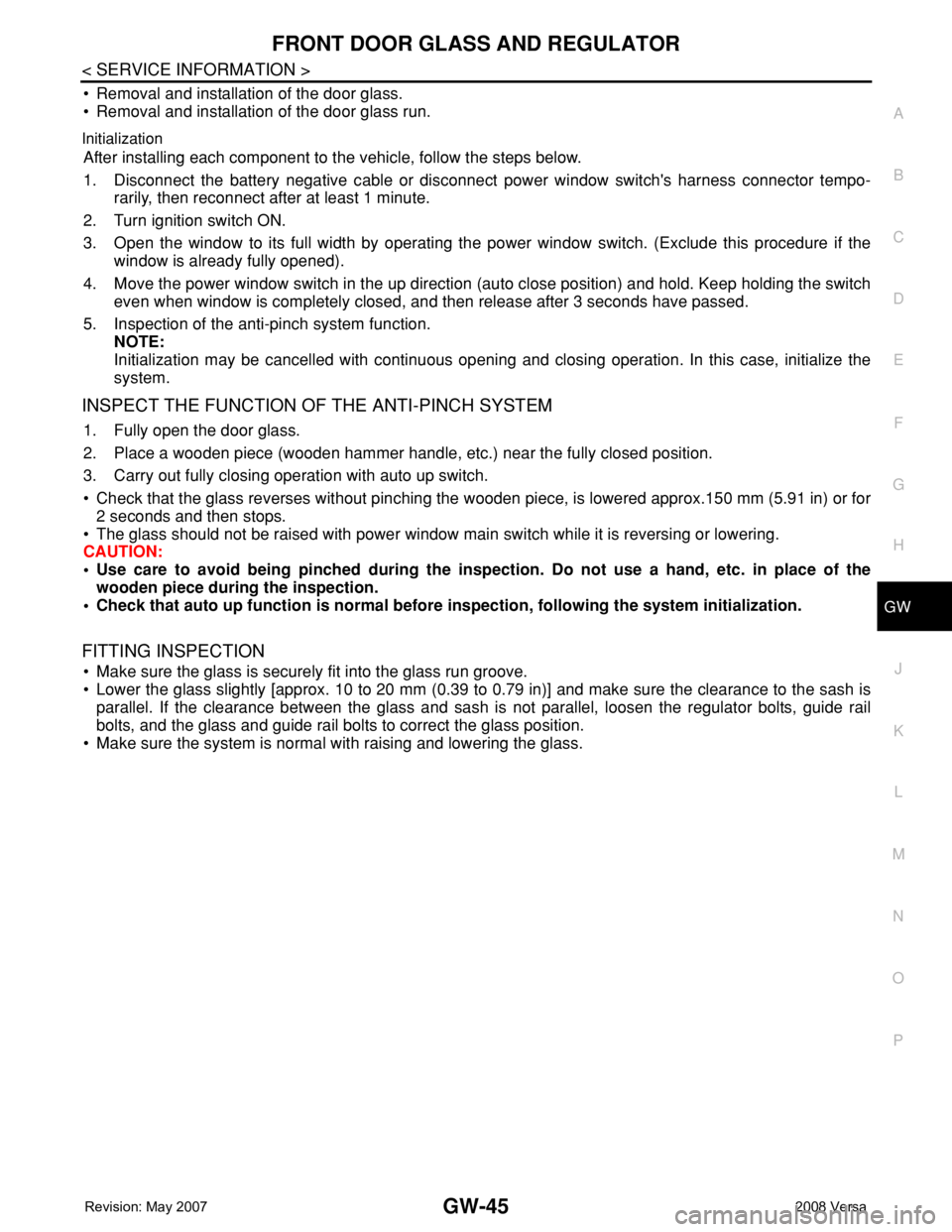
• Removal and installation of the door glass.
• Removal and installation of the door glass run.
Initialization
After installing each component to the vehicle, follow the steps below.
1. Disconnect the battery negative cable or disconnect power window switch's harness connector tempo-
rarily, then reconnect after at least 1 minute.
2. Turn ignition switch ON.
3. Open the window to its full width by operating the power window switch. (Exclude this procedure if the
window is already fully opened).
4. Move the power window switch in the up direction (auto close position) and hold. Keep holding the switch
even when window is completely closed, and then release after 3 seconds have passed.
5. Inspection of the anti-pinch system function.
NOTE:
Initialization may be cancelled with continuous opening and closing operation. In this case, initialize the
system.
INSPECT THE FUNCTION OF THE ANTI-PINCH SYSTEM
1. Fully open the door glass.
2. Place a wooden piece (wooden hammer handle, etc.) near the fully closed position.
3. Carry out fully closing operation with auto up switch.
• Check that the glass reverses without pinching the wooden piece, is lowered approx.150 mm (5.91 in) or for
2 seconds and then stops.
• The glass should not be raised with power window main switch while it is reversing or lowering.
CAUTION:
• Use care to avoid being pinched during the inspection. Do not use a hand, etc. in place of the
wooden piece during the inspection.
• Check that auto up function is normal before inspection, following the system initialization.
FITTING INSPECTION
• Make sure the glass is securely fit into the glass run groove.
• Lower the glass slightly [approx. 10 to 20 mm (0.39 to 0.79 in)] and make sure the clearance to the sash is
parallel. If the clearance between the glass and sash is not parallel, loosen the regulator bolts, guide rail
bolts, and the glass and guide rail bolts to correct the glass position.
• Make sure the system is normal with raising and lowering the glass.
Page 1977 of 2771

INSTRUMENT PANEL ASSEMBLY
IP-11
< ON-VEHICLE REPAIR >
C
D
E
F
G
H
J
K
L
MA
B
IP
N
O
P
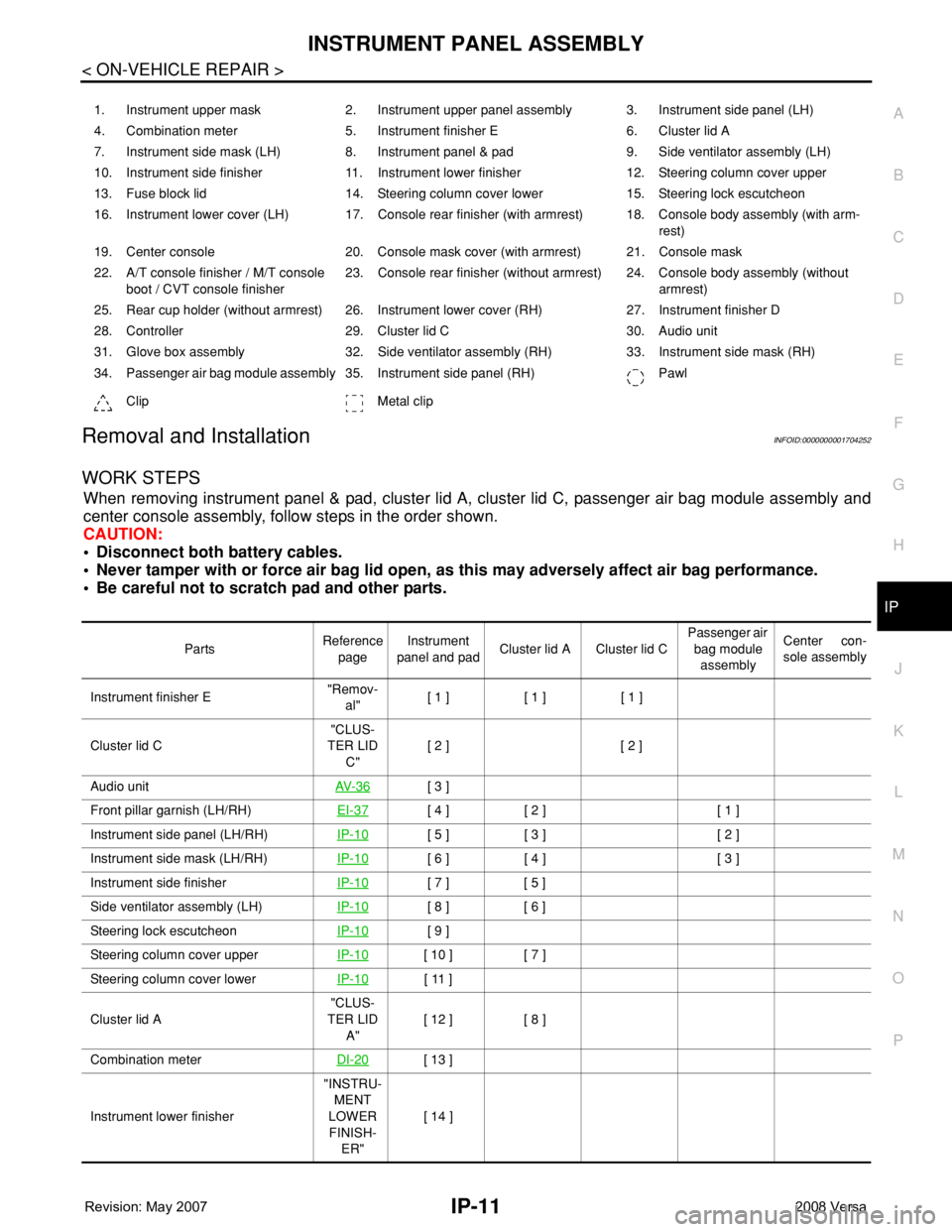
Removal and InstallationINFOID:0000000001704252
WORK STEPS
When removing instrument panel & pad, cluster lid A, cluster lid C, passenger air bag module assembly and
center console assembly, follow steps in the order shown.
CAUTION:
• Disconnect both battery cables.
• Never tamper with or force air bag lid open, as this may adversely affect air bag performance.
• Be careful not to scratch pad and other parts.
1. Instrument upper mask 2. Instrument upper panel assembly 3. Instrument side panel (LH)
4. Combination meter 5. Instrument finisher E 6. Cluster lid A
7. Instrument side mask (LH) 8. Instrument panel & pad 9. Side ventilator assembly (LH)
10. Instrument side finisher 11. Instrument lower finisher 12. Steering column cover upper
13. Fuse block lid 14. Steering column cover lower 15. Steering lock escutcheon
16. Instrument lower cover (LH) 17. Console rear finisher (with armrest) 18. Console body assembly (with arm-
rest)
19. Center console 20. Console mask cover (with armrest) 21. Console mask
22. A/T console finisher / M/T console
boot / CVT console finisher23. Console rear finisher (without armrest) 24. Console body assembly (without
armrest)
25. Rear cup holder (without armrest) 26. Instrument lower cover (RH) 27. Instrument finisher D
28. Controller 29. Cluster lid C 30. Audio unit
31. Glove box assembly 32. Side ventilator assembly (RH) 33. Instrument side mask (RH)
34. Passenger air bag module assembly 35. Instrument side panel (RH) Pawl
Clip Metal clip
PartsReference
pageInstrument
panel and padCluster lid A Cluster lid C Passenger air
bag module
assemblyCenter con-
sole assembly
Instrument finisher E"Remov-
al"[ 1 ] [ 1 ] [ 1 ]
Cluster lid C"CLUS-
TER LID
C"[ 2 ] [ 2 ]
Audio unitAV- 3 6
[ 3 ]
Front pillar garnish (LH/RH)EI-37
[ 4 ] [ 2 ] [ 1 ]
Instrument side panel (LH/RH)IP-10
[ 5 ] [ 3 ] [ 2 ]
Instrument side mask (LH/RH)IP-10
[ 6 ] [ 4 ] [ 3 ]
Instrument side finisherIP-10
[ 7 ] [ 5 ]
Side ventilator assembly (LH)IP-10
[ 8 ] [ 6 ]
Steering lock escutcheonIP-10
[ 9 ]
Steering column cover upperIP-10
[ 10 ] [ 7 ]
Steering column cover lowerIP-10
[ 11 ]
Cluster lid A"CLUS-
TER LID
A"[ 12 ] [ 8 ]
Combination meterDI-20
[ 13 ]
Instrument lower finisher"INSTRU-
MENT
LOWER
FINISH-
ER"[ 14 ]
Page 1993 of 2771

LAN-2
DLC BRANCH LINE CIRCUIT ...........................35
Diagnosis Procedure ..............................................35
EPS BRANCH LINE CIRCUIT ...........................36
Diagnosis Procedure ..............................................36
I-KEY BRANCH LINE CIRCUIT ........................37
Diagnosis Procedure ..............................................37
M&A BRANCH LINE CIRCUIT ..........................38
Diagnosis Procedure ..............................................38
ABS BRANCH LINE CIRCUIT ..........................39
Diagnosis Procedure ..............................................39
TCM BRANCH LINE CIRCUIT ..........................40
Diagnosis Procedure ..............................................40
IPDM-E BRANCH LINE CIRCUIT .....................41
Diagnosis Procedure ..............................................41
CAN COMMUNICATION CIRCUIT ....................42
Diagnosis Procedure ..............................................42
CAN SYSTEM (TYPE 1)
COMPONENT DIAGNOSIS ........................
44
ECM BRANCH LINE CIRCUIT ..........................44
Diagnosis Procedure ..............................................44
BCM BRANCH LINE CIRCUIT ..........................45
Diagnosis Procedure ..............................................45
DLC BRANCH LINE CIRCUIT ...........................46
Diagnosis Procedure ..............................................46
EPS BRANCH LINE CIRCUIT ...........................47
Diagnosis Procedure ..............................................47
M&A BRANCH LINE CIRCUIT ..........................48
Diagnosis Procedure ..............................................48
IPDM-E BRANCH LINE CIRCUIT .....................49
Diagnosis Procedure ..............................................49
CAN COMMUNICATION CIRCUIT ....................50
Diagnosis Procedure ..............................................50
CAN SYSTEM (TYPE 2)
COMPONENT DIAGNOSIS ........................
52
ECM BRANCH LINE CIRCUIT ..........................52
Diagnosis Procedure ..............................................52
BCM BRANCH LINE CIRCUIT ..........................53
Diagnosis Procedure ..............................................53
DLC BRANCH LINE CIRCUIT ...........................54
Diagnosis Procedure ..............................................54
EPS BRANCH LINE CIRCUIT ...........................55
Diagnosis Procedure ..............................................55
I-KEY BRANCH LINE CIRCUIT ........................56
Diagnosis Procedure ...............................................56
M&A BRANCH LINE CIRCUIT ..........................57
Diagnosis Procedure ...............................................57
IPDM-E BRANCH LINE CIRCUIT .....................58
Diagnosis Procedure ...............................................58
CAN COMMUNICATION CIRCUIT ...................59
Diagnosis Procedure ...............................................59
CAN SYSTEM (TYPE 3)
COMPONENT DIAGNOSIS .......................
61
MAIN LINE BETWEEN DLC AND ABS CIR-
CUIT ...................................................................
61
Diagnosis Procedure ...............................................61
ECM BRANCH LINE CIRCUIT ..........................62
Diagnosis Procedure ...............................................62
BCM BRANCH LINE CIRCUIT ..........................63
Diagnosis Procedure ...............................................63
DLC BRANCH LINE CIRCUIT ..........................64
Diagnosis Procedure ...............................................64
EPS BRANCH LINE CIRCUIT ...........................65
Diagnosis Procedure ...............................................65
M&A BRANCH LINE CIRCUIT ..........................66
Diagnosis Procedure ...............................................66
ABS BRANCH LINE CIRCUIT ..........................67
Diagnosis Procedure ...............................................67
IPDM-E BRANCH LINE CIRCUIT .....................68
Diagnosis Procedure ...............................................68
CAN COMMUNICATION CIRCUIT ...................69
Diagnosis Procedure ...............................................69
CAN SYSTEM (TYPE 4)
COMPONENT DIAGNOSIS .......................
71
MAIN LINE BETWEEN DLC AND ABS CIR-
CUIT ...................................................................
71
Diagnosis Procedure ...............................................71
ECM BRANCH LINE CIRCUIT ..........................72
Diagnosis Procedure ...............................................72
BCM BRANCH LINE CIRCUIT ..........................73
Diagnosis Procedure ...............................................73
DLC BRANCH LINE CIRCUIT ..........................74
Diagnosis Procedure ...............................................74
EPS BRANCH LINE CIRCUIT ...........................75
Diagnosis Procedure ...............................................75
I-KEY BRANCH LINE CIRCUIT .....................
Page 1994 of 2771

LAN-3
C
D
E
F
G
H
I
J
L
MA
B
LAN
N
O
P Diagnosis Procedure ...............................................
76
M&A BRANCH LINE CIRCUIT ..........................77
Diagnosis Procedure ...............................................77
ABS BRANCH LINE CIRCUIT ...........................78
Diagnosis Procedure ...............................................78
IPDM-E BRANCH LINE CIRCUIT ......................79
Diagnosis Procedure ...............................................79
CAN COMMUNICATION CIRCUIT ....................80
Diagnosis Procedure ...............................................80
CAN SYSTEM (TYPE 5)
COMPONENT DIAGNOSIS .........................
82
MAIN LINE BETWEEN DLC AND TCM CIR-
CUIT ....................................................................
82
Diagnosis Procedure ...............................................82
ECM BRANCH LINE CIRCUIT ...........................83
Diagnosis Procedure ...............................................83
BCM BRANCH LINE CIRCUIT ..........................84
Diagnosis Procedure ...............................................84
DLC BRANCH LINE CIRCUIT ...........................85
Diagnosis Procedure ...............................................85
EPS BRANCH LINE CIRCUIT ...........................86
Diagnosis Procedure ...............................................86
M&A BRANCH LINE CIRCUIT ..........................87
Diagnosis Procedure ...............................................87
TCM BRANCH LINE CIRCUIT ...........................88
Diagnosis Procedure ...............................................88
IPDM-E BRANCH LINE CIRCUIT ......................89
Diagnosis Procedure ...............................................89
CAN COMMUNICATION CIRCUIT ....................90
Diagnosis Procedure ...............................................90
CAN SYSTEM (TYPE 6)
COMPONENT DIAGNOSIS .........................
92
MAIN LINE BETWEEN DLC AND TCM CIR-
CUIT ....................................................................
92
Diagnosis Procedure ...............................................92
ECM BRANCH LINE CIRCUIT ...........................93
Diagnosis Procedure ...............................................93
BCM BRANCH LINE CIRCUIT ..........................94
Diagnosis Procedure ...............................................94
DLC BRANCH LINE CIRCUIT ...........................95
Diagnosis Procedure ...............................................95
EPS BRANCH LINE CIRCUIT ...........................96
Diagnosis Procedure ...............................................96
M&A BRANCH LINE CIRCUIT .........................97
Diagnosis Procedure ...............................................97
ABS BRANCH LINE CIRCUIT ..........................98
Diagnosis Procedure ...............................................98
TCM BRANCH LINE CIRCUIT ..........................99
Diagnosis Procedure ...............................................99
IPDM-E BRANCH LINE CIRCUIT ...................100
Diagnosis Procedure .............................................100
CAN COMMUNICATION CIRCUIT .................101
Diagnosis Procedure .............................................101
CAN SYSTEM (TYPE 7)
COMPONENT DIAGNOSIS .......................
103
MAIN LINE BETWEEN DLC AND TCM CIR-
CUIT ................................................................
103
Diagnosis Procedure .............................................103
ECM BRANCH LINE CIRCUIT .......................104
Diagnosis Procedure .............................................104
BCM BRANCH LINE CIRCUIT .......................105
Diagnosis Procedure .............................................105
DLC BRANCH LINE CIRCUIT ........................106
Diagnosis Procedure .............................................106
EPS BRANCH LINE CIRCUIT ........................107
Diagnosis Procedure .............................................107
M&A BRANCH LINE CIRCUIT .......................108
Diagnosis Procedure .............................................108
TCM BRANCH LINE CIRCUIT ........................109
Diagnosis Procedure .............................................109
IPDM-E BRANCH LINE CIRCUIT ...................110
Diagnosis Procedure .............................................110
CAN COMMUNICATION CIRCUIT .................111
Diagnosis Procedure .............................................111
CAN SYSTEM (TYPE 8)
COMPONENT DIAGNOSIS .......................
113
MAIN LINE BETWEEN DLC AND TCM CIR-
CUIT ................................................................
113
Diagnosis Procedure .............................................113
ECM BRANCH LINE CIRCUIT .......................114
Diagnosis Procedure .............................................114
BCM BRANCH LINE CIRCUIT .......................115
Diagnosis Procedure .............................................115
DLC BRANCH LINE CIRCUIT ........................116
Diagnosis Procedure .............................................116
EPS BRANCH LINE CIRCUIT ........................117
Page 1995 of 2771

LAN-4
Diagnosis Procedure .............................................117
I-KEY BRANCH LINE CIRCUIT ......................118
Diagnosis Procedure .............................................118
M&A BRANCH LINE CIRCUIT ........................119
Diagnosis Procedure .............................................119
TCM BRANCH LINE CIRCUIT ........................120
Diagnosis Procedure .............................................120
IPDM-E BRANCH LINE CIRCUIT ...................121
Diagnosis Procedure .............................................121
CAN COMMUNICATION CIRCUIT ..................122
Diagnosis Procedure .............................................122
CAN SYSTEM (TYPE 9)
COMPONENT DIAGNOSIS .......................
124
MAIN LINE BETWEEN DLC AND TCM CIR-
CUIT .................................................................
124
Diagnosis Procedure .............................................124
ECM BRANCH LINE CIRCUIT ........................125
Diagnosis Procedure .............................................125
BCM BRANCH LINE CIRCUIT ........................126
Diagnosis Procedure .............................................126
DLC BRANCH LINE CIRCUIT .........................127
Diagnosis Procedure .............................................127
EPS BRANCH LINE CIRCUIT .........................128
Diagnosis Procedure .............................................128
M&A BRANCH LINE CIRCUIT ........................129
Diagnosis Procedure .............................................129
ABS BRANCH LINE CIRCUIT ........................130
Diagnosis Procedure .............................................130
TCM BRANCH LINE CIRCUIT ........................131
Diagnosis Procedure .............................................131
IPDM-E BRANCH LINE CIRCUIT ....................132
Diagnosis Procedure .............................................132
CAN COMMUNICATION CIRCUIT ..................133
Diagnosis Procedure .............................................133
CAN SYSTEM (TYPE 10)
COMPONENT DIAGNOSIS ......................
135
MAIN LINE BETWEEN DLC AND TCM CIR-
CUIT ..................................................................
135
Diagnosis Procedure .............................................135
ECM BRANCH LINE CIRCUIT .........................136
Diagnosis Procedure .............................................136
BCM BRANCH LINE CIRCUIT .........................137
Diagnosis Procedure .............................................137
DLC BRANCH LINE CIRCUIT .........................138
Diagnosis Procedure .............................................138
EPS BRANCH LINE CIRCUIT ..........................139
Diagnosis Procedure .............................................139
I-KEY BRANCH LINE CIRCUIT .......................140
Diagnosis Procedure .............................................140
M&A BRANCH LINE CIRCUIT .........................141
Diagnosis Procedure .............................................141
ABS BRANCH LINE CIRCUIT .........................142
Diagnosis Procedure .............................................142
TCM BRANCH LINE CIRCUIT .........................143
Diagnosis Procedure .............................................143
IPDM-E BRANCH LINE CIRCUIT ....................144
Diagnosis Procedure .............................................144
CAN COMMUNICATION CIRCUIT ..................145
Diagnosis Procedure .............................................145
Page 2001 of 2771
![NISSAN TIIDA 2008 Service Repair Manual LAN-10
< FUNCTION DIAGNOSIS >[CAN FUNDAMENTAL]
TROUBLE DIAGNOSIS
Example: Data link connector branch line open circuit
NOTE:
• When data link connector branch line is open, transmission and receptio NISSAN TIIDA 2008 Service Repair Manual LAN-10
< FUNCTION DIAGNOSIS >[CAN FUNDAMENTAL]
TROUBLE DIAGNOSIS
Example: Data link connector branch line open circuit
NOTE:
• When data link connector branch line is open, transmission and receptio](/manual-img/5/57399/w960_57399-2000.png)
LAN-10
< FUNCTION DIAGNOSIS >[CAN FUNDAMENTAL]
TROUBLE DIAGNOSIS
Example: Data link connector branch line open circuit
NOTE:
• When data link connector branch line is open, transmission and reception of CAN communication signals
are not affected. Therefore, no symptoms occur. However, be sure to repair malfunctioning circuit.
• The model (all units on CAN communication system are Diag on CAN) cannot perform CAN diagnosis with
CONSULT-III if the following error occurs. The error is judged by the symptom.
EPS control unit Normal operation.
Combination meter• Shift position indicator and OD OFF indicator turn OFF.
• Warning lamps turn ON.
ABS actuator and electric unit (control unit) Normal operation.
TCM No impact on operation.
IPDM E/R Normal operation.Unit name Symptom
SKIB8739E
Unit name Symptom
ECM
Normal operation. BCM
EPS control unit
Combination meter
ABS actuator and electric unit (control unit)
TCM
IPDM E/R
Error Difference of symptom
Data link connector branch line open circuit Normal operation.
CAN-H, CAN-L harness short-circuitMost of the units which are connected to the CAN communication
system enter fail-safe mode or are deactivated.
Page 2002 of 2771
![NISSAN TIIDA 2008 Service Repair Manual TROUBLE DIAGNOSIS
LAN-11
< FUNCTION DIAGNOSIS >[CAN FUNDAMENTAL]
C
D
E
F
G
H
I
J
L
MA
B
LAN
N
O
P Example: Main Line Between Data Link Connector and ABS Actuator and Electric Unit (Control Unit) Open NISSAN TIIDA 2008 Service Repair Manual TROUBLE DIAGNOSIS
LAN-11
< FUNCTION DIAGNOSIS >[CAN FUNDAMENTAL]
C
D
E
F
G
H
I
J
L
MA
B
LAN
N
O
P Example: Main Line Between Data Link Connector and ABS Actuator and Electric Unit (Control Unit) Open](/manual-img/5/57399/w960_57399-2001.png)
TROUBLE DIAGNOSIS
LAN-11
< FUNCTION DIAGNOSIS >[CAN FUNDAMENTAL]
C
D
E
F
G
H
I
J
L
MA
B
LAN
N
O
P Example: Main Line Between Data Link Connector and ABS Actuator and Electric Unit (Control Unit) Open Circuit
Example: CAN-H, CAN-L Harness Short Circuit
SKIB8740E
Unit name Symptom
ECM Engine torque limiting is affected, and shift harshness increases.
BCM• Reverse warning chime does not sound.
• The front wiper moves under continuous operation mode even though the front wip-
er switch being in the intermittent position.
EPS control unit The steering effort increases.
Combination meter• The shift position indicator and OD OFF indicator turn OFF.
• The speedometer is inoperative.
• The odo/trip meter stops.
ABS actuator and electric unit (control unit) Normal operation.
TCM No impact on operation.
IPDM E/RWhen the ignition switch is ON,
• The headlamps (Lo) turn ON.
• The cooling fan continues to rotate.
SKIB8741E
Page 2003 of 2771
![NISSAN TIIDA 2008 Service Repair Manual LAN-12
< FUNCTION DIAGNOSIS >[CAN FUNDAMENTAL]
TROUBLE DIAGNOSIS
CAN Diagnosis with CONSULT-III
INFOID:0000000001711207
CAN diagnosis on CONSULT-III extracts the root cause by receiving the following NISSAN TIIDA 2008 Service Repair Manual LAN-12
< FUNCTION DIAGNOSIS >[CAN FUNDAMENTAL]
TROUBLE DIAGNOSIS
CAN Diagnosis with CONSULT-III
INFOID:0000000001711207
CAN diagnosis on CONSULT-III extracts the root cause by receiving the following](/manual-img/5/57399/w960_57399-2002.png)
LAN-12
< FUNCTION DIAGNOSIS >[CAN FUNDAMENTAL]
TROUBLE DIAGNOSIS
CAN Diagnosis with CONSULT-III
INFOID:0000000001711207
CAN diagnosis on CONSULT-III extracts the root cause by receiving the following information.
• Response to the system call
• Control unit diagnosis information
• Self-diagnosis
• CAN diagnostic support monitor
Self-DiagnosisINFOID:0000000001711208
CAN Diagnostic Support MonitorINFOID:0000000001711209
MONITOR ITEM (CONSULT-III)
Unit name Symptom
ECM• Engine torque limiting is affected, and shift harshness increases.
• Engine speed drops.
BCM• Reverse warning chime does not sound.
• The front wiper moves under continuous operation mode even though the front
wiper switch being in the intermittent position.
• The room lamp does not turn ON.
• The engine does not start (if an error or malfunction occurs while turning the igni-
tion switch OFF.)
• The steering lock does not release (if an error or malfunction occurs while turning
the ignition switch OFF.)
EPS control unit The steering effort increases.
Combination meter• The tachometer and the speedometer do not move.
• Warning lamps turn ON.
• Indicator lamps do not turn ON.
ABS actuator and electric unit (control unit) Normal operation.
TCM No impact on operation.
IPDM E/RWhen the ignition switch is ON,
• The headlamps (Lo) turn ON.
• The cooling fan continues to rotate.
DTCSelf-diagnosis item
(CONSULT-III indication)DTC detection condition Inspection/Action
U1000 CAN COMM CIRCUITWhen ECM is not transmitting or receiving CAN
communication signal of OBD (emission-related
diagnosis) for 2 seconds or more.
Start the inspection. Re-
fer to the applicable sec-
tion of the indicated
control unit. When a control unit (except for ECM) is not
transmitting or receiving CAN communication
signal for 2 seconds or more.
U1001 CAN COMM CIRCUITWhen ECM is not transmitting or receiving CAN
communication signal other than OBD (emis-
sion-related diagnosis) for 2 seconds or more.
U1002 SYSTEM COMMWhen a control unit is not transmitting or receiv-
ing CAN communication signal for 2 seconds or
less.
U1010 CONTROL UNIT [CAN]When an error is detected during the initial diag-
nosis for CAN controller of each control unit.Replace the control unit
indicating “U1010”.