2008 NISSAN TEANA CVT Control Valve
[x] Cancel search: CVT Control ValvePage 1012 of 5121
![NISSAN TEANA 2008 Service Manual TCS
BRC-71
< FUNCTION DIAGNOSIS >[VDC/TCS/ABS]
C
D
E
G
H
I
J
K
L
MA
B
BRC
N
O
P
TCS
System DiagramINFOID:0000000003767312
System DescriptionINFOID:0000000003766890
Traction Control System is a funct](/manual-img/5/57391/w960_57391-1011.png "NISSAN TEANA 2008 Service Manual TCS
BRC-71
< FUNCTION DIAGNOSIS >[VDC/TCS/ABS]
C
D
E
G
H
I
J
K
L
MA
B
BRC
N
O
P
TCS
System DiagramINFOID:0000000003767312
System DescriptionINFOID:0000000003766890
Traction Control System is a funct")
TCS
BRC-71
< FUNCTION DIAGNOSIS >[VDC/TCS/ABS]
C
D
E
G
H
I
J
K
L
MA
B
BRC
N
O
P
TCS
System DiagramINFOID:0000000003767312
System DescriptionINFOID:0000000003766890
Traction Control System is a function that electronically controls engine torque, brake fluid pressure and
CVT shift position to ensure the optimum slippage ratio at drive wheels by computing wheel speed signals
from 4 wheel sensors. When ABS actuator and electric unit (control unit) detects a spin at drive wheels (rear
wheels), it compares wheel speed signals from all 4 wheels. At this time, LH and RH rear brake fluid pres-
sure are controlled, while fuel being cut to engine and throttle valve being closed to reduce engine torque by
the control unit. Further more, throttle position is continuously controlled to ensure the optimum engine
torque at all times.
During TCS operation, TCS informs driver of system operation by flashing SLIP indicator lamp.
Electrical system diagnosis by CONSULT-III is available.
JSFIA0259GB
Page 1465 of 5121

EC-4
DTC Logic ..............................................................249
Diagnosis Procedure .............................................249
P1217 ENGINE OVER TEMPERATURE .........250
DTC Logic ..............................................................250
Component Function Check ..................................250
Diagnosis Procedure .............................................251
P1225 TP SENSOR .........................................254
Description .............................................................254
DTC Logic ..............................................................254
Diagnosis Procedure .............................................254
Special Repair Requirement ..................................255
P1226 TP SENSOR .........................................256
Description .............................................................256
DTC Logic ..............................................................256
Diagnosis Procedure .............................................256
Special Repair Requirement ..................................257
P1550 BATTERY CURRENT SENSOR ..........258
Description .............................................................258
DTC Logic ..............................................................258
Diagnosis Procedure .............................................258
Component Inspection ...........................................259
P1551, P1552 BATTERY CURRENT SEN-
SOR ..................................................................
261
Description .............................................................261
DTC Logic ..............................................................261
Diagnosis Procedure .............................................261
Component Inspection ...........................................262
P1553 BATTERY CURRENT SENSOR ..........264
Description .............................................................264
DTC Logic ..............................................................264
Diagnosis Procedure .............................................264
Component Inspection ...........................................265
P1554 BATTERY CURRENT SENSOR ..........267
Description .............................................................267
DTC Logic ..............................................................267
Component Function Check ..................................267
Diagnosis Procedure .............................................268
Component Inspection ...........................................269
P1564 ASCD STEERING SWITCH .................270
Description .............................................................270
DTC Logic ..............................................................270
Diagnosis Procedure .............................................270
Component Inspection ...........................................272
P1572 ASCD BRAKE SWITCH .......................273
Description .............................................................273
DTC Logic ..............................................................273
Diagnosis Procedure .............................................274
Component Inspection (ASCD Brake Switch) .......277
Component Inspection (Stop Lamp Switch) ..........277
P1574 ASCD VEHICLE SPEED SENSOR ......278
Description .............................................................278
DTC Logic .............................................................278
Diagnosis Procedure .............................................278
P1700 CVT CONTROL SYSTEM .....................280
Description ............................................................280
P1715 INPUT SPEED SENSOR (PRIMARY
SPEED SENSOR) .............................................
281
Description ............................................................281
DTC Logic .............................................................281
Diagnosis Procedure .............................................281
P1720 VSS ........................................................283
Description ............................................................283
DTC Logic .............................................................283
Diagnosis Procedure .............................................283
P1800 VIAS CONTROL SOLENOID VALVE 1 ..285
Description ............................................................285
DTC Logic .............................................................285
Diagnosis Procedure .............................................285
Component Inspection ..........................................286
P1801 VIAS CONTROL SOLENOID VALVE 2 ..288
Description ............................................................288
DTC Logic .............................................................288
Diagnosis Procedure .............................................288
Component Inspection ..........................................289
P1805 BRAKE SWITCH ...................................291
Description ............................................................291
DTC Logic .............................................................291
Diagnosis Procedure .............................................291
Component Inspection (Stop Lamp Switch) ..........292
P2100, P2103 THROTTLE CONTROL MO-
TOR RELAY .....................................................
294
Description ............................................................294
DTC Logic .............................................................294
Diagnosis Procedure .............................................294
P2101 ELECTRIC THROTTLE CONTROL
FUNCTION ........................................................
296
Description ............................................................296
DTC Logic .............................................................296
Diagnosis Procedure .............................................296
Component Inspection ..........................................298
Special Repair Requirement .................................299
P2118 THROTTLE CONTROL MOTOR ..........300
Description ............................................................300
DTC Logic .............................................................300
Component Inspection ..........................................300
Special Repair Requirement .................................300
P2119 ELECTRIC THROTTLE CONTROL
ACTUATOR ......................................................
302
Description ............................................................302
DTC Logic .............................................................302
Diagnosis Procedure .............................................303
Special Repair Requirement .................................303
Page 1477 of 5121
![NISSAN TEANA 2008 Service Manual EC-16
< BASIC INSPECTION >[VQ25DE, VQ35DE]
INSPECTION AND ADJUSTMENT
THROTTLE VALVE CLOSED POSITION LEARNING
THROTTLE VALVE CLOSED POSITION LEARNING : DescriptionINFOID:0000000003856455
Throttle Valve](/manual-img/5/57391/w960_57391-1476.png "NISSAN TEANA 2008 Service Manual EC-16
< BASIC INSPECTION >[VQ25DE, VQ35DE]
INSPECTION AND ADJUSTMENT
THROTTLE VALVE CLOSED POSITION LEARNING
THROTTLE VALVE CLOSED POSITION LEARNING : DescriptionINFOID:0000000003856455
Throttle Valve")
EC-16
< BASIC INSPECTION >[VQ25DE, VQ35DE]
INSPECTION AND ADJUSTMENT
THROTTLE VALVE CLOSED POSITION LEARNING
THROTTLE VALVE CLOSED POSITION LEARNING : DescriptionINFOID:0000000003856455
Throttle Valve Closed Position Learning is an operation to learn the fully closed position of the throttle valve by
monitoring the throttle position sensor output signal. It must be performed each time harness connector of
electric throttle control actuator or ECM is disconnected.
THROTTLE VALVE CLOSED POSITION LEARNING : Special Repair Requirement
INFOID:0000000003856456
1.START
1. Check that accelerator pedal is fully released.
2. Turn ignition switch ON.
3. Turn ignition switch OFF and wait at least 10 seconds.
Check that throttle valve moves during above 10 seconds by confirming the operating sound.
>> END
IDLE AIR VOLUME LEARNING
IDLE AIR VOLUME LEARNING : DescriptionINFOID:0000000003856457
Idle Air Volume Learning is a function of ECM to learn the idle air volume that keeps engine idle speed within
the specific range. It must be performed under the following conditions:
Each time electric throttle control actuator or ECM is replaced.
Idle speed or ignition timing is out of specification.
IDLE AIR VOLUME LEARNING : Special Repair RequirementINFOID:0000000003856458
1.PRECONDITIONING
Before performing Idle Air Volume Learning, check that all of the following conditions are satisfied.
Learning will be cancelled if any of the following conditions are missed for even a moment.
Battery voltage: More than 12.9 V (At idle)
Engine coolant temperature: 70 - 100°C (158 - 212°F)
Selector lever: P or N
Electric load switch: OFF
(Air conditioner, head lamp, rear window defogger)
-For vehicle equipped with daytime light systems, perform one of the following procedures before
starting engine not to illuminate headlamps.
Apply parking brake
Set lighting switch to the 1st position
Steering wheel: Neutral (Straight-ahead position)
Vehicle speed: Stopped
Transmission: Warmed-up
- With CONSULT-III: Drive vehicle until “ATF TEMP SEN” in “DATA MONITOR” mode of “CVT” system indi-
cates less than 0.9 V.
- Without CONSULT-III: Drive vehicle for 10 minutes.
Will CONSULT-III be used?
YES >> GO TO 2.
NO >> GO TO 3.
2.PERFORM IDLE AIR VOLUME LEARNING
With CONSULT-III
1. Perform EC-15, "
ACCELERATOR PEDAL RELEASED POSITION LEARNING : Special Repair Require-
ment".
2. Perform EC-16, "
THROTTLE VALVE CLOSED POSITION LEARNING : Special Repair Requirement".
3. Start engine and warm it up to normal operating temperature.
4. Select “IDLE AIR VOL LEARN” in “WORK SUPPORT” mode.
5. Touch “START” and wait 20 seconds.
Page 1849 of 5121
![NISSAN TEANA 2008 Service Manual EC-388
< ECU DIAGNOSIS >[VQ25DE, VQ35DE]
ECM
DTC Inspection Priority Chart
INFOID:0000000003856871
If some DTCs are displayed at the same time, perform inspections one by one based on the following pr](/manual-img/5/57391/w960_57391-1848.png "NISSAN TEANA 2008 Service Manual EC-388
< ECU DIAGNOSIS >[VQ25DE, VQ35DE]
ECM
DTC Inspection Priority Chart
INFOID:0000000003856871
If some DTCs are displayed at the same time, perform inspections one by one based on the following pr")
EC-388
< ECU DIAGNOSIS >[VQ25DE, VQ35DE]
ECM
DTC Inspection Priority Chart
INFOID:0000000003856871
If some DTCs are displayed at the same time, perform inspections one by one based on the following priority
chart.
P2119 Electric throttle control ac-
tuator(When electric throttle control actuator does not function properly due to the return spring
malfunction:)
ECM controls the electric throttle actuator by regulating the throttle opening around the
idle position. The engine speed will not rise more than 2,000 rpm.
(When throttle valve opening angle in fail-safe mode is not in specified range:)
ECM controls the electric throttle control actuator because of regulating the throttle open-
ing to 20 degrees or less.
(When ECM detects the throttle valve is stuck open:)
While the vehicle is being driver, it slows down gradually by fuel cut. After the vehicle
stops, the engine stalls.
The engine can restart in N or P position, and engine speed will not exceed 1,000 rpm or
more.
P2122
P2123
P2127
P2128
P2138Accelerator pedal position
sensorThe ECM controls the electric throttle control actuator in regulating the throttle opening in
order for the idle position to be within +10 degrees.
The ECM regulates the opening speed of the throttle valve to be slower than the normal
condition.
So, the acceleration will be poor. DTC No. Detected items Engine operating condition in fail-safe mode
Priority Detected items (DTC)
1 U1000 U1001 CAN communication line
P0102 P0103 Mass air flow sensor
P0112 P0113 Intake air temperature sensor
P0117 P0118 Engine coolant temperature sensor
P0122 P0123 P0222 P0223 P1225 P1226 P2135 Throttle position sensor
P0327 P0328 P0332 P0333 Knock sensor
P0335 Crankshaft position sensor (POS)
P0340 P0345 Camshaft position sensor (PHASE)
P0500 Vehicle speed sensor
P0605 P0607 ECM
P0643 Sensor power supply
P0705 P0850 Park/Neutral position (PNP) switch
P1550 P1551 P1552 P1553 P1554 Battery current sensor
P1610 - P1615 NATS
P1700 CVT control system
P2122 P2123 P2127 P2128 P2138 Accelerator pedal position sensor
Page 1850 of 5121
![NISSAN TEANA 2008 Service Manual ECM
EC-389
< ECU DIAGNOSIS >[VQ25DE, VQ35DE]
C
D
E
F
G
H
I
J
K
L
MA
EC
N
P O
DTC IndexINFOID:0000000003856872
×:Applicable —: Not applicable
2 P0031 P0032 P0051 P0052 Air fuel ratio (A/F) sensor](/manual-img/5/57391/w960_57391-1849.png "NISSAN TEANA 2008 Service Manual ECM
EC-389
< ECU DIAGNOSIS >[VQ25DE, VQ35DE]
C
D
E
F
G
H
I
J
K
L
MA
EC
N
P O
DTC IndexINFOID:0000000003856872
×:Applicable —: Not applicable
2 P0031 P0032 P0051 P0052 Air fuel ratio (A/F) sensor")
ECM
EC-389
< ECU DIAGNOSIS >[VQ25DE, VQ35DE]
C
D
E
F
G
H
I
J
K
L
MA
EC
N
P O
DTC IndexINFOID:0000000003856872
×:Applicable —: Not applicable
2 P0031 P0032 P0051 P0052 Air fuel ratio (A/F) sensor 1 heater
P0037 P0038 P0057 P0058 Heated oxygen sensor 2 heater
P0075 P0081 Intake valve timing control solenoid valve
P0130 P0131 P0132 P0133 P0150 P0151 P0152 P0153 P2A00 P2A03 Air fuel ratio (A/F) sensor 1
P0137 P0138 P0139 P0157 P0158 P0159 Heated oxygen sensor 2
P0444 EVAP canister purge volume control solenoid valve
P0550 Power steering pressure sensor
P0603 ECM power supply
P0710 P0715 P0720 P0740 P0744 P0745 P0746 P0776 P0778 P0840 P0845 P1740 CVT related sensors, solenoid valves
and switches
P1217 Engine over temperature (OVERHEAT)
P1720 Vehicle speed sensor
P1777 P1778 CVT step motor
P1800 P1801 VIAS control solenoid valve
P1805 Brake switch
P2100 P2103 Throttle control motor relay
P2101 Electric throttle control function
P2118 Throttle control motor
3 P0011 P0021 Intake valve timing control
P0171 P0172 P0174 P0175 Fuel injection system function
P0300 - P0306 Misfire
P0420 P0430 Three way catalyst function
P1212 TCS communication line
P1564 ASCD steering switch
P1572 ASCD brake switch
P1574 ASCD vehicle speed sensor
P1715 Primary speed sensor
P2119 Electric throttle control actuator Priority Detected items (DTC)
Items
(CONSULT-III screen terms)DTC*
1
SRT code Trip MIReference
page CONSULT-III
GST*
2ECM*3
CAN COMM CIRCUIT U1000
1000*4—1×EC-135
CAN COMM CIRCUIT U1001
1001*4—2 —EC-135
NO DTC IS DETECTED.
FURTHER TESTING
MAY BE REQUIRED.P0000 0000——
Flashing*6—
INT/V TIM CONT-B1 P0011 0011 — 2 —EC-136
INT/V TIM CONT-B2 P0021 0021 — 2 —EC-136
A/F SEN1 HTR (B1) P0031 0031 — 2×EC-140
A/F SEN1 HTR (B1) P0032 0032 — 2×EC-140
HO2S2 HTR (B1) P0037 0037 — 2×EC-143
HO2S2 HTR (B1) P0038 0038 — 2×EC-143
A/F SEN1 HTR (B2) P0051 0051 — 2×EC-140
A/F SEN1 HTR (B2) P0052 0052 — 2×EC-140
HO2S2 HTR (B2) P0057 0057 — 2×EC-143
HO2S2 HTR (B2) P0058 0058 — 2×EC-143
INT/V TIM V/CIR-B1 P0075 0075 — 2×EC-146
INT/V TIM V/CIR-B2 P0081 0081 — 2×EC-146
MAF SEN/CIRCUIT-B1 P0102 0102 — 1×EC-149
MAF SEN/CIRCUIT-B1 P0103 0103 — 1×EC-149
Page 1967 of 5121
EM-92
< DISASSEMBLY AND ASSEMBLY >
CAMSHAFT
b. Disconnect ignition coil and injector harness connectors. Refer to EM-49, "Exploded View" and EM-44,
"Exploded View".
3. Remove intake valve timing control solenoid valve. Refer to EM-79, "
Exploded View".
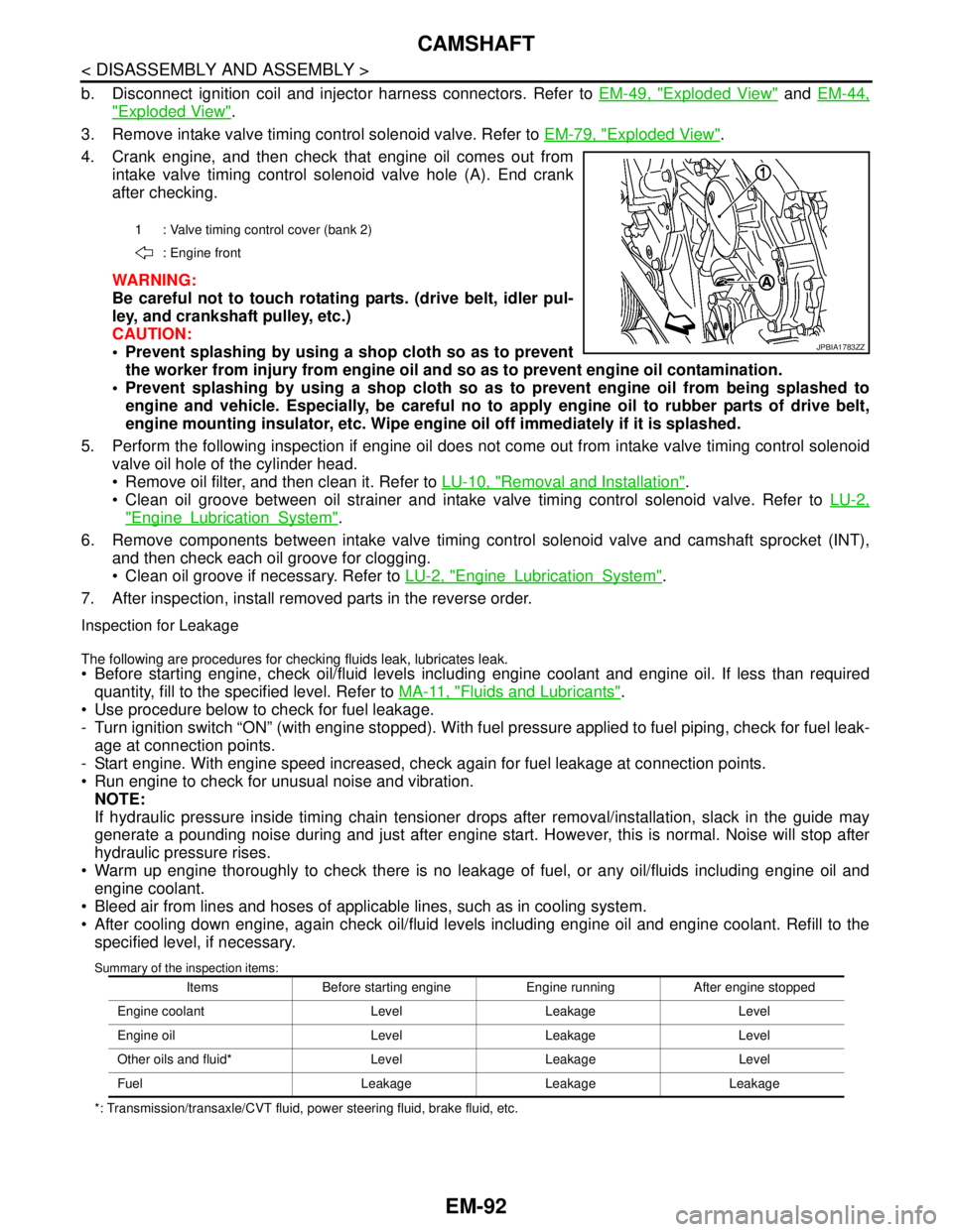
4. Crank engine, and then check that engine oil comes out from
intake valve timing control solenoid valve hole (A). End crank
after checking.
WARNING:
Be careful not to touch rotating parts. (drive belt, idler pul-
ley, and crankshaft pulley, etc.)
CAUTION:
Prevent splashing by using a shop cloth so as to prevent
the worker from injury from engine oil and so as to prevent engine oil contamination.
Prevent splashing by using a shop cloth so as to prevent engine oil from being splashed to
engine and vehicle. Especially, be careful no to apply engine oil to rubber parts of drive belt,
engine mounting insulator, etc. Wipe engine oil off immediately if it is splashed.
5. Perform the following inspection if engine oil does not come out from intake valve timing control solenoid
valve oil hole of the cylinder head.
Remove oil filter, and then clean it. Refer to LU-10, "
Removal and Installation".
Clean oil groove between oil strainer and intake valve timing control solenoid valve. Refer to LU-2,
"EngineLubricationSystem".
6. Remove components between intake valve timing control solenoid valve and camshaft sprocket (INT),
and then check each oil groove for clogging.
Clean oil groove if necessary. Refer to LU-2, "
EngineLubricationSystem".
7. After inspection, install removed parts in the reverse order.
Inspection for Leakage
The following are procedures for checking fluids leak, lubricates leak. Before starting engine, check oil/fluid levels including engine coolant and engine oil. If less than required
quantity, fill to the specified level. Refer to MA-11, "
Fluids and Lubricants".
Use procedure below to check for fuel leakage.
- Turn ignition switch “ON” (with engine stopped). With fuel pressure applied to fuel piping, check for fuel leak-
age at connection points.
- Start engine. With engine speed increased, check again for fuel leakage at connection points.
Run engine to check for unusual noise and vibration.
NOTE:
If hydraulic pressure inside timing chain tensioner drops after removal/installation, slack in the guide may
generate a pounding noise during and just after engine start. However, this is normal. Noise will stop after
hydraulic pressure rises.
Warm up engine thoroughly to check there is no leakage of fuel, or any oil/fluids including engine oil and
engine coolant.
Bleed air from lines and hoses of applicable lines, such as in cooling system.
After cooling down engine, again check oil/fluid levels including engine oil and engine coolant. Refill to the
specified level, if necessary.
Summary of the inspection items:
*: Transmission/transaxle/CVT fluid, power steering fluid, brake fluid, etc.1 : Valve timing control cover (bank 2)
: Engine front
JPBIA1783ZZ
Items Before starting engine Engine running After engine stopped
Engine coolant Level Leakage Level
Engine oil Level Leakage Level
Other oils and fluid* Level Leakage Level
Fuel Leakage Leakage Leakage
Page 4475 of 5121

TM-2
DTC Logic ...............................................................47
Diagnosis Procedure ..............................................47
Component Inspection ............................................48
P0710 CVT FLUID TEMPERATURE SENSOR
...
50
Description ..............................................................50
DTC Logic ...............................................................50
Diagnosis Procedure ..............................................50
Component Inspection (CVT Fluid Temperature
Sensor) ...................................................................
51
P0715 INPUT SPEED SENSOR (PRI SPEED
SENSOR) ...........................................................
52
Description ..............................................................52
DTC Logic ...............................................................52
Diagnosis Procedure ..............................................52
P0720 VEHICLE SPEED SENSOR CVT (SEC-
ONDARY SPEED SENSOR) .............................
55
Description ..............................................................55
DTC Logic ...............................................................55
Diagnosis Procedure ..............................................55
P0725 ENGINE SPEED SIGNAL ......................59
Description ..............................................................59
DTC Logic ...............................................................59
Diagnosis Procedure ..............................................59
P0730 BELT DAMAGE ......................................60
Description ..............................................................60
DTC Logic ...............................................................60
Diagnosis Procedure ..............................................60
P0740 TORQUE CONVERTER CLUTCH SO-
LENOID VALVE .................................................
62
Description ..............................................................62
DTC Logic ...............................................................62
Diagnosis Procedure ..............................................62
Component Inspection (Torque Converter Clutch
Solenoid Valve) ......................................................
63
P0744 A/T TCC S/V FUNCTION (LOCK -UP) ...64
Description ..............................................................64
DTC Logic ...............................................................64
Diagnosis Procedure ..............................................64
Component Inspection (Torque Converter Clutch
Solenoid Valve) ......................................................
65
Component Inspection (Lock-up Select Solenoid
Valve) .....................................................................
65
P0745 LINE PRESSURE SOLENOID VALVE ...66
Description ..............................................................66
DTC Logic ...............................................................66
Diagnosis Procedure ..............................................66
Component Inspection [Pressure Control Sole-
noid Valve A (Line Pressure Solenoid Valve)] ........
67
P0746 PRESSURE CONTROL SOLENOID A
PERFORMANCE (LINE PRESSURE SOLE-
NOID VALVE) ....................................................
68
Description ..............................................................68
DTC Logic ...............................................................68
Diagnosis Procedure ...............................................68
Component Inspection [Pressure Control Sole-
noid Valve A (Line Pressure Solenoid Valve)] ........
69
P0776 PRESSURE CONTROL SOLENOID B
PERFORMANCE (SEC PRESSURE SOLE-
NOID VALVE) ....................................................
70
Description ..............................................................70
DTC Logic ...............................................................70
Diagnosis Procedure ...............................................70
Component Inspection [Pressure Control Sole-
noid Valve A (Line Pressure Solenoid Valve)] ........
71
Component Inspection [Pressure Control Sole-
noid Valve B (Secondary Pressure Solenoid
Valve)] .....................................................................
71
P0778 PRESSURE CONTROL SOLENOID B
ELECTRICAL (SEC PRESSURE SOLENOID
VALVE) ..............................................................
72
Description ..............................................................72
DTC Logic ...............................................................72
Diagnosis Procedure ...............................................72
Component Inspection [Pressure Control Sole-
noid Valve B (Secondary Pressure Solenoid
Valve)] .....................................................................
73
P0840 TRANSMISSION FLUID PRESSURE
SENSOR A (SEC PRESSURE SENSOR) .........
74
Description ..............................................................74
DTC Logic ...............................................................74
Diagnosis Procedure ...............................................74
P0841 PRESSURE SENSOR FUNCTION ........77
Description ..............................................................77
DTC Logic ...............................................................77
Diagnosis Procedure ...............................................77
Component Inspection [Pressure Control Sole-
noid Valve A (Line Pressure Solenoid Valve)] ........
78
Component Inspection [Pressure Control Sole-
noid Valve B (Secondary Pressure Solenoid
Valve)] .....................................................................
78
P0845 TRANSMISSION FLUID PRESSURE
SENSOR B (PRI PRESSURE SENSOR) ..........
80
Description ..............................................................80
DTC Logic ...............................................................80
Diagnosis Procedure ...............................................80
P0868 SECONDARY PRESSURE DOWN ........83
Description ..............................................................83
DTC Logic ...............................................................83
Diagnosis Procedure ...............................................83
Component Inspection [Pressure Control Sole-
noid Valve A (Line Pressure Solenoid Valve)] ........
84
Page 4476 of 5121
![NISSAN TEANA 2008 Service Manual TM-3
C
E
F
G
H
I
J
K
L
MA
B
TM
N
O
P Component Inspection [Pressure Control Sole-
noid Valve B (Secondary Pressure Solenoid
Valve)] ...................................................................](/manual-img/5/57391/w960_57391-4475.png "NISSAN TEANA 2008 Service Manual TM-3
C
E
F
G
H
I
J
K
L
MA
B
TM
N
O
P Component Inspection [Pressure Control Sole-
noid Valve B (Secondary Pressure Solenoid
Valve)] ...................................................................")
TM-3
C
E
F
G
H
I
J
K
L
MA
B
TM
N
O
P Component Inspection [Pressure Control Sole-
noid Valve B (Secondary Pressure Solenoid
Valve)] .....................................................................
84
P1701 TRANSMISSION CONTROL MODULE
(POWER SUPPLY) .............................................
85
Description ..............................................................85
DTC Logic ...............................................................85
Diagnosis Procedure ...............................................85
P1705 THROTTLE POSITION SENSOR ...........88
Description ..............................................................88
DTC Logic ...............................................................88
Diagnosis Procedure ...............................................88
P1722 ESTM VEHICLE SPEED SIGNAL ..........89
Description ..............................................................89
DTC Logic ...............................................................89
Diagnosis Procedure ...............................................89
P1723 CVT SPEED SENSOR FUNCTION ........91
Description ..............................................................91
DTC Logic ...............................................................91
Diagnosis Procedure ...............................................91
P1726 ELECTRIC THROTTLE CONTROL
SYSTEM .............................................................
93
Description ..............................................................93
DTC Logic ...............................................................93
Diagnosis Procedure ...............................................93
P1740 LOCK-UP SELECT SOLENOID
VALVE ................................................................
94
Description ..............................................................94
DTC Logic ...............................................................94
Diagnosis Procedure ...............................................94
Component Inspection (Lock-up Select Solenoid
Valve) ......................................................................
95
P1745 LINE PRESSURE CONTROL .................96
Description ..............................................................96
DTC Logic ...............................................................96
Diagnosis Procedure ...............................................96
P1777 STEP MOTOR .........................................97
Description ..............................................................97
DTC Logic ...............................................................97
Diagnosis Procedure ...............................................97
Component Inspection (Step Motor) .......................98
P1778 STEP MOTOR - FUNCTION .................100
Description ............................................................100
DTC Logic .............................................................100
Diagnosis Procedure .............................................100
SHIFT POSITION INDICATOR CIRCUIT .........102
Description ............................................................102
Component Function Check ..................................102
Diagnosis Procedure .............................................102
SHIFT LOCK SYSTEM .....................................103
Description .............................................................103
Wiring Diagram - CVT SHIFT LOCK SYSTEM - ...103
Component Function Check ..................................105
Diagnosis Procedure .............................................106
Component Inspection (Stop Lamp Switch) ..........107
SPORT MODE SWITCH .................................108
Description .............................................................108
Component Function Check ..................................108
Diagnosis Procedure .............................................108
ECU DIAGNOSIS .......................................111
TCM .................................................................111
Reference Value ....................................................111
Wiring Diagram - CVT CONTROL SYSTEM - .......116
Fail-safe .................................................................120
DTC Inspection Priority Chart ................................121
DTC Index .............................................................121
SYMPTOM DIAGNOSIS ............................123
SYSTEM SYMPTOM .......................................123
Symptom Table .....................................................123
PRECAUTION ............................................135
PRECAUTIONS ...............................................135
Precaution for Supplemental Restraint System
(SRS) "AIR BAG" and "SEAT BELT PRE-TEN-
SIONER" ...............................................................
135
Precaution Necessary for Steering Wheel Rota-
tion after Battery Disconnect .................................
135
Precaution for Procedure without Cowl Top Cover ..136
Precaution for On Board Diagnosis (OBD) System
of CVT and Engine ................................................
136
Precaution for TCM and CVT Assembly Replace-
ment .......................................................................
136
Removal and Installation Procedure for CVT Unit
Connector ..............................................................
136
Precaution .............................................................138
Service Notice or Precaution .................................138
ATFTEMP COUNT Conversion Table ...................139
PREPARATION .........................................140
PREPARATION ...............................................140
Special Service Tools ............................................140
Commercial Service Tools .....................................140
ON-VEHICLE MAINTENANCE ..................142
CVT FLUID ......................................................142
Inspection ..............................................................142
Changing ...............................................................143
STALL TEST ...................................................144
Inspection and Judgment ......................................144
LINE PRESSURE TEST ..................................146
Inspection and Judgment ......................................146