2008 NISSAN TEANA parking brake
[x] Cancel search: parking brakePage 3850 of 5121
RSU-18
< REMOVAL AND INSTALLATION >
REAR SUSPENSION MEMBER
REAR SUSPENSION MEMBER
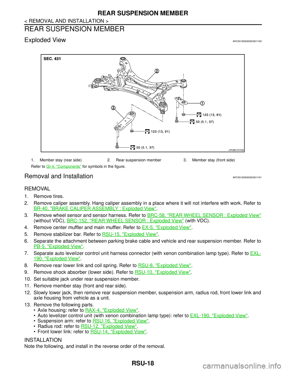
Exploded ViewINFOID:0000000003811160
Removal and InstallationINFOID:0000000003811161
REMOVAL
1. Remove tires.
2. Remove caliper assembly. Hang caliper assembly in a place where it will not interfere with work. Refer to
BR-40, "
BRAKE CALIPER ASSEMBLY : Exploded View".
3. Remove wheel sensor and sensor harness. Refer to BRC-58, "
REAR WHEEL SENSOR : Exploded View"
(without VDC), BRC-152, "REAR WHEEL SENSOR : Exploded View" (with VDC).
4. Remove center muffler and main muffler. Refer to EX-5, "
Exploded View".
5. Remove stabilizer bar. Refer to RSU-15, "
Exploded View".
6. Separate the attachment between parking brake cable and vehicle and rear suspension member. Refer to
PB-5, "
Exploded View".
7. Separate auto levelizer control unit harness connector (with xenon combination lamp type). Refer to EXL-
190, "Exploded View".
8. Remove rear lower link and coil spring. Refer to RSU-8, "
Exploded View".
9. Remove shock absorber (lower side). Refer to RSU-10, "
Exploded View".
10. Set suitable jack under rear suspension member.
11. Remove member stay (front and rear side).
12. Slowly lower jack, then remove rear suspension member, suspension arm, radius rod, front lower link and
axle housing from vehicle as a unit.
13. Remove the following parts.
Axle housing: refer to RAX-4, "
Exploded View".
Auto levelizer control unit (with xenon combination lamp type): refer to EXL-190, "
Exploded View".
Suspension arm: refer to RSU-16, "
Exploded View".
Radius rod: refer to RSU-12, "
Exploded View".
Front lower link: refer to RSU-14, "
Exploded View".
INSTALLATION
Note the following, and install in the reverse order of the removal.
1. Member stay (rear side) 2. Rear suspension member 3. Member stay (front side)
Refer to GI-4, "
Components" for symbols in the figure.
JPEIB0107GB
Page 3851 of 5121
REAR SUSPENSION MEMBER
RSU-19
< REMOVAL AND INSTALLATION >
C
D
F
G
H
I
J
K
L
MA
B
RSU
N
O
P
Perform the final tightening of each of parts under unladen conditions, which were removed when removing
rear suspension assembly.
After final tightening, install auto levelizer control unit (with xenon combination lamp type). Refer to EXL-190,
"Exploded View".
Never reuse cotter pin.
InspectionINFOID:0000000003811162
INSPECTION AFTER REMOVAL
Check rear suspension member for deformation, cracks, or any other damage. Replace if necessary.
INSPECTION AFTER INSTALLATION
1. Check wheel sensor harness for proper connection. Refer to BRC-58, "REAR WHEEL SENSOR :
Exploded View" (without VDC), BRC-152, "REAR WHEEL SENSOR : Exploded View" (with VDC).
2. Adjust parking brake operation (stroke). PB-2, "
Inspection and Adjustment".
3. Check wheel alignment. Refer to RSU-6, "
Inspection".
4. Adjust neutral position of steering angle sensor. Refer to BRC-66, "
ADJUSTMENT OF STEERING
ANGLE SENSOR NEUTRAL POSITION : Special Repair Requirement".
Page 3856 of 5121
SB-4
< ON-VEHICLE REPAIR >
FRONT SEAT BELT
6. Remove the clip fixing the seat belt and check that the webbing returns smoothly.
6. Repeat steps above as necessary to check the other seat belts.
SEAT BELT RETRACTOR ON-VEHICLE CHECK
Emergency Locking Retractors (ELR) and Automatic Locking Retractors (ALR)
NOTE:
All seat belt retractors are Emergency Locking Retractors (ELR) type. In an emergency (sudden stop) the
retractor will lock and prevent the webbing from extending any further. All 3-point type seat belt retractors
except the driver seat belt also have an Automatic Locking Retractors (ALR) mode. The ALR mode (also
called child restraint mode) is used when installing child seats. The ALR mode is activated when the seat belt
is fully extended. When the webbing is then retracted partially, the ALR mode automatically locks the seat belt
in a specific position so the webbing cannot be extended any further. To cancel the ALR mode, allow the seat
belt to fully wind back into the retractor.
Check the seat belt retractors with the following test(s) to determine if a retractor assembly is operating prop-
erly.
ELR Function Stationary Check
Grasp the shoulder webbing and pull forward quickly. The retractor should lock and prevent the belt from
extending further.
ALR Function Stationary Check
1. Pull out the entire length of seat belt from retractor until a click is heard.
2. Retract the webbing partially. A clicking noise should be heard as the webbing retracts indicating that the
retractor is in the Automatic Locking Retractors (ALR) mode.
3. Grasp the seat belt and try to pull out the retractor. The webbing must lock and not extend any further. If
NG, replace the retractor assembly.
4. Allow the entire length of the webbing to retract to cancel the automatic locking mode.
ELR Function Moving Check
WARNING:
Perform the following test in a safe, open area clear of other vehicles and obstructions (for example, a
large, empty parking lot). Road surface must be paved and dry. Never perform the following test on
wet or gravel roads or on public streets and highways. This could result in an accident and serious
personal injury. The driver and passenger must be prepared to brace themselves in the event that the
retractor does not lock.
1. Fasten driver seat belt. Buckle a passenger into the seat for the belt that is to be tested.
2. Proceed to the designated safe area.
3. Drive the vehicle at approximately 16 km/h (10 MPH). Notify any passengers of a pending sudden stop
and the driver and passenger must be prepared to brace themselves in the event that the retractor does
not lock, apply brakes firmly and make a very hard stop.
During stopping, seat belts should lock and not be extended. If the seat belt retractor assembly does not lock,
perform the retractor off-vehicle check.
SEAT BELT RETRACTOR OFF-VEHICLE CHECK
1. Remove the seat belt retractor.
Remove the front seat belt assembly, refer to SB-5, "
SEAT BELT RETRACTOR : Removal and Installa-
tion".
2. Slowly pull out webbing while tilting the retractor assembly forward from the mounted position without
twisting the retractor assembly as shown in the illustration.
Page 3861 of 5121
REAR SEAT BELT
SB-9
< ON-VEHICLE REPAIR >
C
D
E
F
G
I
J
K
L
MA
B
SB
N
O
P
Grasp the shoulder webbing and pull forward quickly. The retractor should lock and prevent the belt from
extending further.
ALR Function Stationary Check
1. Pull out the entire length of seat belt from retractor until a click is heard.
2. Retract the webbing partially. A clicking noise should be heard as the webbing retracts indicating that the
retractor is in the Automatic Locking Retractors (ALR) mode.
3. Grasp the seat belt and try to pull out the retractor. The webbing must lock and not extend any further. If
NG, replace the retractor assembly.
4. Allow the entire length of the webbing to retract to cancel the automatic locking mode.
ELR Function Moving Check
WARNING:
Perform the following test in a safe, open area clear of other vehicles and obstructions (for example, a
large, empty parking lot). Road surface must be paved and dry. NEVER perform the following test on
wet or gravel roads or on public streets and highways. This could result in an accident and serious
personal injury. The driver and passenger must be prepared to brace themselves in the event that the
retractor does not lock.
1. Fasten driver seat belt. Buckle a passenger into the seat for the belt that is to be tested.
2. Proceed to the designated safe area.
3. Drive the vehicle at approximately 16 km/h (10 MPH). Notify any passengers of a pending sudden stop
and the driver and passenger must be prepared to brace themselves in the event that the retractor does
not lock, apply brakes firmly and make a very hard stop.
During stopping, seat belts should lock and not be extended. If the seat belt retractor assembly does not lock,
perform the retractor off-vehicle check.
SEAT BELT RETRACTOR OFF-VEHICLE CHECK
1. Remove the seat belt retractor.
Remove the rear seat belt assembly, refer to SB-10, "
SEAT BELT RETRACTOR : Removal and Installa-
tion".
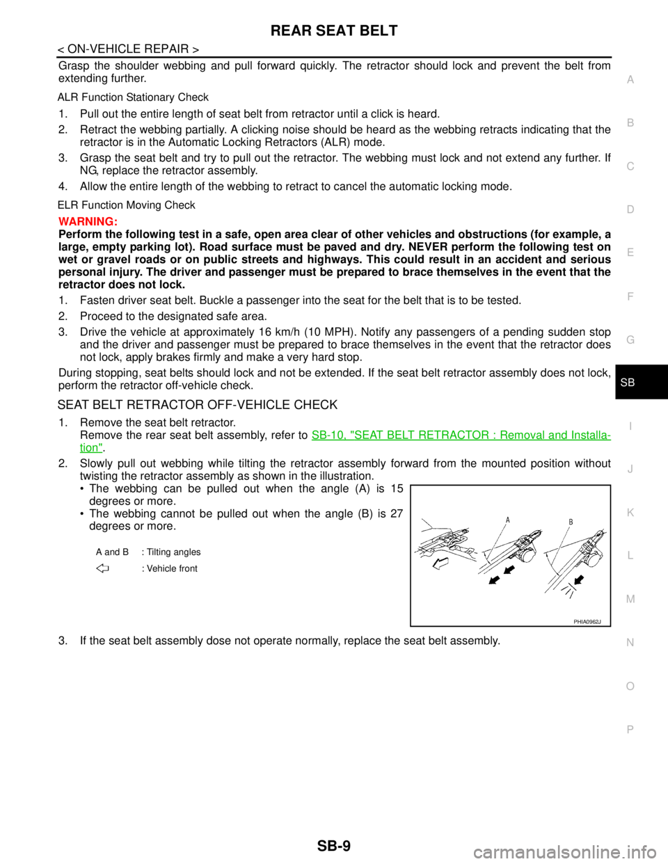
2. Slowly pull out webbing while tilting the retractor assembly forward from the mounted position without
twisting the retractor assembly as shown in the illustration.
The webbing can be pulled out when the angle (A) is 15
degrees or more.
The webbing cannot be pulled out when the angle (B) is 27
degrees or more.
3. If the seat belt assembly dose not operate normally, replace the seat belt assembly.
A and B : Tilting angles
: Vehicle front
PHIA0962J
Page 4399 of 5121
STEERING WHEEL
ST-9
< ON-VEHICLE MAINTENANCE >
C
D
E
F
H
I
J
K
L
MA
B
ST
N
O
P
STEERING WHEEL
InspectionINFOID:0000000003806313
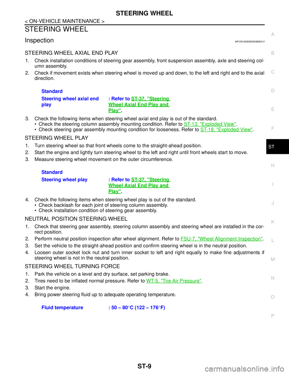
STEERING WHEEL AXIAL END PLAY
1. Check installation conditions of steering gear assembly, front suspension assembly, axle and steering col-
umn assembly.
2. Check if movement exists when steering wheel is moved up and down, to the left and right and to the axial
direction.
3. Check the following items when steering wheel axial end play is out of the standard.
Check the steering column assembly mounting condition. Refer to ST-13, "
Exploded View".
Check steering gear assembly mounting condition for looseness. Refer to ST-18, "
Exploded View".
STEERING WHEEL PLAY
1. Turn steering wheel so that front wheels come to the straight-ahead position.
2. Start the engine and lightly turn steering wheel to the left and right until front wheels start to move.
3. Measure steering wheel movement on the outer circumference.
4. Check the following items when steering wheel play is out of the standard.
Check backlash for each joint of steering column assembly.
Check installation condition of steering gear assembly.
NEUTRAL POSITION STEERING WHEEL
1. Check that steering gear assembly, steering column assembly and steering wheel are installed in the cor-
rect position.
2. Perform neutral position inspection after wheel alignment. Refer to FSU-7, "
Wheel Alignment Inspection".
3. Set the vehicle to the straight-ahead position and confirm steering wheel is in the neutral position.
4. Loosen outer socket lock nut and turn inner socket to left and right equally to make fine adjustments if
steering wheel is not in the neutral position.
STEERING WHEEL TURNING FORCE
1. Park the vehicle on a level and dry surface, set parking brake.
2. Tires need to be inflated normal pressure. Refer to WT-5, "
Tire Air Pressure".
3. Start the engine.
4. Bring power steering fluid up to adequate operating temperature.Standard
Steering wheel axial end
play: Refer to ST-37, "
Steering
Wheel Axial End Play and
Play".
Standard
Steering wheel play : Refer to ST-37, "
Steering
Wheel Axial End Play and
Play".
Fluid temperature : 50 – 80°C (122 – 176°F)
Page 4489 of 5121
![NISSAN TEANA 2008 Service Manual TM-16
< FUNCTION DIAGNOSIS >[CVT: RE0F09B]
MECHANICAL SYSTEM
MECHANICAL SYSTEM
Cross-Sectional ViewINFOID:0000000003848919
1. Converter housing 2. Oil pump 3. Forward clutch
4. Reverse brake 5. Planet](/manual-img/5/57391/w960_57391-4488.png "NISSAN TEANA 2008 Service Manual TM-16
< FUNCTION DIAGNOSIS >[CVT: RE0F09B]
MECHANICAL SYSTEM
MECHANICAL SYSTEM
Cross-Sectional ViewINFOID:0000000003848919
1. Converter housing 2. Oil pump 3. Forward clutch
4. Reverse brake 5. Planet")
TM-16
< FUNCTION DIAGNOSIS >[CVT: RE0F09B]
MECHANICAL SYSTEM
MECHANICAL SYSTEM
Cross-Sectional ViewINFOID:0000000003848919
1. Converter housing 2. Oil pump 3. Forward clutch
4. Reverse brake 5. Planetary carrier 6. Primary pulley
7. Steel belt 8. Sun gear 9. Side cover
10. Internal gear 11. Secondary pulley 12. Final gear
13. Differential case 14. Idler gear 15. Reduction gear
16. Taper roller bearing 17. Output gear 18. Parking gear
19. Input shaft 20. Torque converter
SCIA7859E
Page 4492 of 5121
![NISSAN TEANA 2008 Service Manual MECHANICAL SYSTEM
TM-19
< FUNCTION DIAGNOSIS >[CVT: RE0F09B]
C
E
F
G
H
I
J
K
L
MA
B
TM
N
O
P
CVT fluid temperature sensor
Secondary pressure sensor
ROM assembly
Component DescriptionINFOID:00000](/manual-img/5/57391/w960_57391-4491.png "NISSAN TEANA 2008 Service Manual MECHANICAL SYSTEM
TM-19
< FUNCTION DIAGNOSIS >[CVT: RE0F09B]
C
E
F
G
H
I
J
K
L
MA
B
TM
N
O
P
CVT fluid temperature sensor
Secondary pressure sensor
ROM assembly
Component DescriptionINFOID:00000")
MECHANICAL SYSTEM
TM-19
< FUNCTION DIAGNOSIS >[CVT: RE0F09B]
C
E
F
G
H
I
J
K
L
MA
B
TM
N
O
P
CVT fluid temperature sensor
Secondary pressure sensor
ROM assembly
Component DescriptionINFOID:0000000003848923
Item Function
Torque converterThe torque converter is the device that increases the engine torque as well as the con-
ventional AT and transmits it to the transaxle.
Oil pumpThe adoption of a trochoidal oil pump with a flow control valve actuated directly by the
engine enables the sufficient discharge from an oil pump in the low-rpm range and the
adequate discharge adjustments in the high-rpm range.
Planetary gear
Perform the transmission of drive power and the switching of forward/backward move-
ment. Forward clutch
Reverse brake
Primary pulley It is composed of a pair of pulleys (the groove width is changed freely in the axial direc-
tion) and the steel belt (the steel star wheels are placed continuously and the belt is guid-
ed with the multilayer steel rings on both sides). The groove width changes according to
wrapping radius of steel belt and pulley from low status to overdrive status continuously
with non-step. It is controlled with the oil pressures of primary pulley and secondary pul-
ley. Secondary pulley
Steel belt
Output gear
Reduction gear consists of primary deceleration (output gear and idler gear in pair) and
secondary deceleration (reduction gear and final gear in pair). Each of them uses a he-
lical gear. Idler gear
Reduction gear
Final gear
Differential
Manual shaft
The parking rod rotates the parking pole and the parking pole engages with the parking
gear when the manual shaft is in “P” position. As a result the parking gear and the output
axis are fixed. Parking rod
Parking pawl
Parking gear
Page 4597 of 5121
![NISSAN TEANA 2008 Service Manual TM-124
< SYMPTOM DIAGNOSIS >[CVT: RE0F09B]
SYSTEM SYMPTOM
4
Slips/Will
Not EngageVehicle cannot take
off from “D” position.ON vehicle1. CVT fluid level and stateTM-142
2. CVT positionTM-152
3. C](/manual-img/5/57391/w960_57391-4596.png "NISSAN TEANA 2008 Service Manual TM-124
< SYMPTOM DIAGNOSIS >[CVT: RE0F09B]
SYSTEM SYMPTOM
4
Slips/Will
Not EngageVehicle cannot take
off from “D” position.ON vehicle1. CVT fluid level and stateTM-142
2. CVT positionTM-152
3. C")
TM-124
< SYMPTOM DIAGNOSIS >[CVT: RE0F09B]
SYSTEM SYMPTOM
4
Slips/Will
Not EngageVehicle cannot take
off from “D” position.ON vehicle1. CVT fluid level and stateTM-142
2. CVT positionTM-152
3. CAN communication lineTM-41
4. Line pressure testTM-146
5. Stall testTM-144
6. Step motorTM-97
7. Primary speed sensorTM-52
8. Secondary speed sensorTM-55
9. Accelerator pedal position sensorTM-88
10. CVT fluid temperature sensorTM-50
11. Secondary pressure sensorTM-74
12. TCM power supply and groundTM-85
OFF vehicle13. Oil pump assembly
TM-16814. Forward clutch
15. Control valve
16. Parking components
5Vehicle cannot take
off from “R” position.ON vehicle1. CVT fluid level and stateTM-142
2. CVT positionTM-152
3. CAN communication lineTM-41
4. Line pressure testTM-146
5. Stall testTM-144
6. Step motorTM-97
7. Primary speed sensorTM-52
8. Secondary speed sensorTM-55
9. Accelerator pedal position sensorTM-88
10. CVT fluid temperature sensorTM-50
11. Secondary pressure sensorTM-74
12. TCM power supply and groundTM-85
OFF vehicle13. Oil pump assembly
TM-16814. Reverse brake
15. Control valve
16. Parking components No. Item Symptom Condition Diagnostic item Reference