2008 NISSAN TEANA parking brake
[x] Cancel search: parking brakePage 3261 of 5121

MWI
METER SYSTEM
MWI-7
< FUNCTION DIAGNOSIS >
C
D
E
F
G
H
I
J
K
L
MB A
O
P
System Description Signal source
Meter/gaugeSpeedometer Receives vehicle speed signal and indicates vehicle speed.ABS actuator and elec-
tric unit (control unit)
Tachometer Receives engine speed signal and indicates engine speed. ECM
Fuel gauge Receives fuel level sensor signal and indicates fuel level. Fuel level sensor unit
Engine coolant tem-
perature gaugeReceives engine coolant temperature signal and indicates coolant
temperature.ECM
Warning lamp/
indicator lampOil pressure warning
lampReceives oil pressure warning lamp signal and illuminates warning
lamp.IPDM E/R
Master warning Illuminates according to warning output on information display. —
Information
displayDoor open warning Receives door switch signals and displays warning. BCM
Trunk open warning Receives trunk switch signals and displays warning. BCM
Parking brake re-
lease warningReceives parking brake switch signal and vehicle speed signal and
displays warnings.Parking brake switch
ABS actuator and elec-
tric unit (control unit)
Low fuel warningReceives fuel gauge signal and displays warning if fuel level de-
creases to 11 (2-2/5 Imp gal) or less.Fuel level sensor unit
Low outside tempera-
ture warningMonitors ambient sensor signal and displays warning if ambient
temperature decreases to 3°C (37°F) or less. (If enabled)Ambient sensor
Instantaneous fuel
consumptionCalculates instantaneous fuel consumption based on received ve-
hicle speed signals and fuel consumption monitor signal and dis-
plays it.ECM
ABS actuator and elec-
tric unit (control unit)
Average fuel con-
sumptionCalculates average fuel consumption in a reset-to-reset interval
based on received vehicle speed signals and fuel consumption
monitor signal and displays it.ECM
ABS actuator and elec-
tric unit (control unit)
Average vehicle
speedCalculates average vehicle speed in a reset-to-reset interval based
on received vehicle speed signals and displays it.ABS actuator and elec-
tric unit (control unit)
Travel time Displays accumulated key switch ON time from reset to reset. —
Travel distanceCalculates accumulated travel distance in a reset-to-reset interval
based on received vehicle speed signals and displays it.ABS actuator and elec-
tric unit (control unit)
Possible driving dis-
tanceCalculates possible driving distance based on received fuel con-
sumption monitor signal, vehicle speed signals and fuel level sen-
sor signal and displays it.ABS actuator and elec-
tric unit (control unit)
ECM
Fuel level sensor unit
Ambient air tempera-
tureCorrects ambient air temperature value based on received ambient
sensor signals and displays it.Ambient sensor
Page 3264 of 5121
MWI-10
< FUNCTION DIAGNOSIS >
METER SYSTEM
METER SYSTEM : Component Description
INFOID:0000000003792510
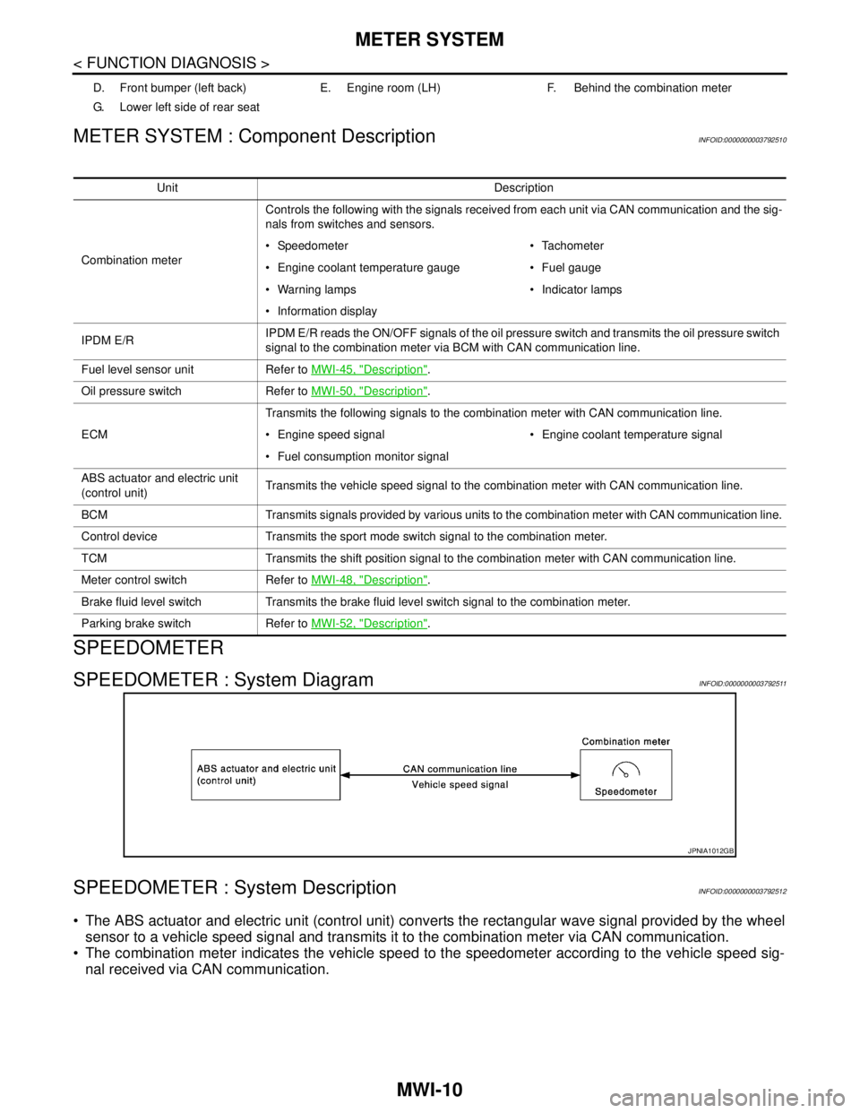
SPEEDOMETER
SPEEDOMETER : System DiagramINFOID:0000000003792511
SPEEDOMETER : System DescriptionINFOID:0000000003792512
The ABS actuator and electric unit (control unit) converts the rectangular wave signal provided by the wheel
sensor to a vehicle speed signal and transmits it to the combination meter via CAN communication.
The combination meter indicates the vehicle speed to the speedometer according to the vehicle speed sig-
nal received via CAN communication.
D. Front bumper (left back) E. Engine room (LH) F. Behind the combination meter
G. Lower left side of rear seat
Unit Description
Combination meterControls the following with the signals received from each unit via CAN communication and the sig-
nals from switches and sensors.
Speedometer Tachometer
Engine coolant temperature gauge Fuel gauge
Warning lamps Indicator lamps
Information display
IPDM E/RIPDM E/R reads the ON/OFF signals of the oil pressure switch and transmits the oil pressure switch
signal to the combination meter via BCM with CAN communication line.
Fuel level sensor unit Refer to MWI-45, "
Description".
Oil pressure switch Refer to MWI-50, "
Description".
ECMTransmits the following signals to the combination meter with CAN communication line.
Engine speed signal Engine coolant temperature signal
Fuel consumption monitor signal
ABS actuator and electric unit
(control unit)Transmits the vehicle speed signal to the combination meter with CAN communication line.
BCM Transmits signals provided by various units to the combination meter with CAN communication line.
Control device Transmits the sport mode switch signal to the combination meter.
TCM Transmits the shift position signal to the combination meter with CAN communication line.
Meter control switch Refer to MWI-48, "
Description".
Brake fluid level switch Transmits the brake fluid level switch signal to the combination meter.
Parking brake switch Refer to MWI-52, "
Description".
JPNIA1012GB
Page 3281 of 5121
MWI
METER SYSTEM
MWI-27
< FUNCTION DIAGNOSIS >
C
D
E
F
G
H
I
J
K
L
MB A
O
P
METER ILLUMINATION CONTROL : Component DescriptionINFOID:0000000003796391
INFORMATION DISPLAY
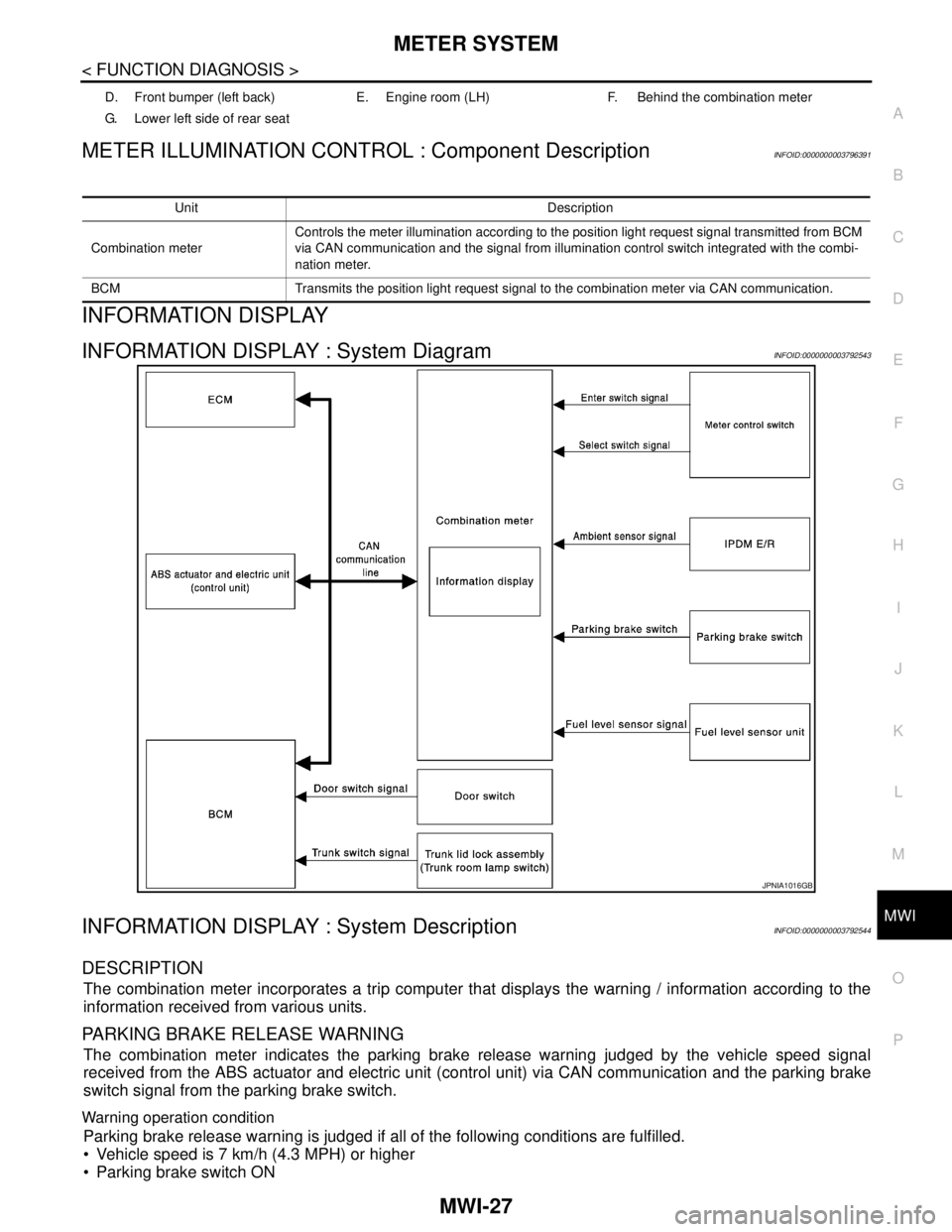
INFORMATION DISPLAY : System DiagramINFOID:0000000003792543
INFORMATION DISPLAY : System DescriptionINFOID:0000000003792544
DESCRIPTION
The combination meter incorporates a trip computer that displays the warning / information according to the
information received from various units.
PARKING BRAKE RELEASE WARNING
The combination meter indicates the parking brake release warning judged by the vehicle speed signal
received from the ABS actuator and electric unit (control unit) via CAN communication and the parking brake
switch signal from the parking brake switch.
Warning operation condition
Parking brake release warning is judged if all of the following conditions are fulfilled.
Vehicle speed is 7 km/h (4.3 MPH) or higher
Parking brake switch ON
D. Front bumper (left back) E. Engine room (LH) F. Behind the combination meter
G. Lower left side of rear seat
Unit Description
Combination meterControls the meter illumination according to the position light request signal transmitted from BCM
via CAN communication and the signal from illumination control switch integrated with the combi-
nation meter.
BCM Transmits the position light request signal to the combination meter via CAN communication.
JPNIA1016GB
Page 3285 of 5121
MWI
METER SYSTEM
MWI-31
< FUNCTION DIAGNOSIS >
C
D
E
F
G
H
I
J
K
L
MB A
O
P
INFORMATION DISPLAY : Component DescriptionINFOID:0000000003792546
D. Front bumper (left back) E. Engine room (LH) F. Behind the combination meter
G. Lower left side of rear seat
Unit Description
Combination meter Controls the information display according to the signal received from each unit.
Fuel level sensor unit Refer to MWI-45, "
Description".
ECMTransmits the following signals to the combination meter via CAN communication.
Engine speed signal
Fuel consumption monitor signal
ABS actuator and electric unit
(control unit)Transmits the vehicle speed signal to the combination meter via CAN communication.
BCM Transmits signals provided by various units to the combination meter via CAN communication.
Meter control switchTransmits the following signals to the combination meter.
Enter switch signal
Select switch signal
Parking brake switch Refer to MWI-52, "
Description".
Door switch Transmits the door switch signals to BCM.
Trunk room lamp switch Transmits the trunk room lamp switch signal to BCM
Ambient sensorDetects the ambient air temperature and transmits the ambient sensor signal to the combination
meter.
Page 3288 of 5121
![NISSAN TEANA 2008 Service Manual MWI-34
< FUNCTION DIAGNOSIS >
DIAGNOSIS SYSTEM (METER)
W TEMP METER
[°C] XValue of engine coolant temperature signal is received from ECM via CAN com-
munication.
NOTE:
215 is displayed when the mal](/manual-img/5/57391/w960_57391-3287.png "NISSAN TEANA 2008 Service Manual MWI-34
< FUNCTION DIAGNOSIS >
DIAGNOSIS SYSTEM (METER)
W TEMP METER
[°C] XValue of engine coolant temperature signal is received from ECM via CAN com-
munication.
NOTE:
215 is displayed when the mal")
MWI-34
< FUNCTION DIAGNOSIS >
DIAGNOSIS SYSTEM (METER)
W TEMP METER
[°C] XValue of engine coolant temperature signal is received from ECM via CAN com-
munication.
NOTE:
215 is displayed when the malfunction signal is input.
ABS W/L
[On/Off]Status of ABS warning lamp detected from ABS warning lamp signal is received
from ABS actuator and electric unit (control unit) via CAN communication.
VDC/TCS IND
[On/Off]Status of VDC OFF indicator lamp detected from VDC OFF indicator lamp signal
is received from ABS actuator and electric unit (control unit) via CAN communica-
tion.
SLIP IND
[On/Off]Status of SLIP indicator lamp detected from slip indicator lamp signal received
from ABS actuator and electric unit (control unit) via CAN communication.
BRAKE W/L
[On/Off]Status of brake warning lamp detected from brake warning lamp signal is received
from ABS actuator and electric unit (control unit) via CAN communication.
NOTE:
Displays “Off” if the brake warning lamp is illuminated when the valve check starts,
the parking brake switch is turned ON or the brake fluid level switch is turned ON.
DOOR W/L
[On/Off]Status of door warning detected from door switch signal received from BCM via
CAN communication.
TRUNK/GLAS-H
[On/Off]Status of trunk warning detected from trunk switch signal received from BCM via
CAN communication.
HI-BEAM IND
[On/Off]Status of high beam indicator lamp detected from high beam request signal is re-
ceived from BCM via CAN communication.
TURN IND
[On/Off]Status of turn indicator lamp detected from turn indicator signal is received from
BCM via CAN communication.
FR FOG IND
[On/Off]Status of front fog light indicator lamp detected from front fog light request signal
is received from BCM via CAN communication.
RR FOG IND
[On/Off]Status of rear fog light indicator lamp detected from rear fog light request signal is
received from BCM via CAN communication.
LIGHT IND
[On/Off]Status of light indicator lamp detected from position light request signal is received
from BCM via CAN communication.
OIL W/L
[On/Off]Status of oil pressure warning lamp detected from oil pressure switch signal is re-
ceived from BCM via CAN communication.
MIL
[On/Off] Status of malfunction indicator lamp detected from malfunctioning indicator lamp
signal is received from ECM via CAN communication.
CRUISE IND
[On/Off]Status of CRUISE indicator detected from ASCD status signal is received from
ECM via CAN communication.
SPORT IND
[On/Off]Status of SPORT indicator detected from sport mode switch signal is received
from control device.
4WD W/L
[On/Off]This item is displayed, but cannot be monitored.
4WD LOCK IND
[On/Off]This item is displayed, but cannot be monitored.
FUEL W/L
[On/Off]Low-fuel warning lamp status detected by the identified fuel level.
WASHER W/L
[On/Off]This item is displayed, but cannot be monitored.
KEY G/Y W/L
[On/Off]Status of key warning lamp (G/Y) detected from key warning signal is received
from BCM via CAN communication.
AFS OFF IND
[On/Off]This item is displayed, but cannot be monitored.
LCD
[B&P N, B&P I, ID NG, ROTAT, SFT
P, INSRT, BATT, NO KY,OUTKY, LK
WN]Displays status of Intelligent Key system warning detected from meter display sig-
nal is received from BCM via CAN communication. Display item [Unit]MAIN
SIGNALSDescription
Page 3289 of 5121
MWI
DIAGNOSIS SYSTEM (METER)
MWI-35
< FUNCTION DIAGNOSIS >
C
D
E
F
G
H
I
J
K
L
MB A
O
P
NOTE:
Some items are not available according to vehicle specification.
SPECIAL FUNCTION
Special menu
W/L ON HISTORY
Stores histories when warning/indicator lamp is turned on.
“W/L ON HISTORY” indicates the “TIME” when the warning/ indicator lamp is turned on.
The “TIME” above is :
SHIFT IND
[P, R, N, D, L]Status of shift position indicator detected from shift position signal and manual
mode indicator signal is received from TCM via CAN communication.
O/D OFF SW
[On/Off] Status of sport mode switch.
M RANGE SW
[On/Off]This item is displayed, but cannot be monitored.
NM RANGE SW
[On/Off]This item is displayed, but cannot be monitored.
AT SFT UP SW
[On/Off]This item is displayed, but cannot be monitored.
AT SFT DWN SW
[On/Off]This item is displayed, but cannot be monitored.
ST SFT UP SW
[On/Off]This item is displayed, but cannot be monitored.
ST SFT DWN SW
[On/Off]This item is displayed, but cannot be monitored.
PKB SW
[On/Off]Status of parking brake switch.
BUCKLE SW
[On/Off]Status of seat belt buckle switch.
BRAKE OIL SW
[On/Off]Status of brake fluid level switch.
DISTANCE
[km]Value of possible driving distance calculated by combination meter.
A/C AMP CONN
[On/Off]Input status of A/C auto amp. connection recognition signal.
ENTER SW
[On/Off]Status of (ENTER) switch.
SELECT SW
[On/Off]Status of (SELECT) switch.
OUTSIDE TEMP
[°C or °F]Ambient air temperature value converted from ambient sensor signal received
from ambient sensor.
NOTE:
This may not match with the temperature value indicated on the information dis-
play. (Because the information display value is a corrected value from the ambient
sensor input value.)
FUEL LOW SIG
[On/Off]Status of fuel level low warning signal to output to AV control unit via CAN com-
munication.
BUZZER
[On/Off]XBuzzer status (in the combination meter) is detected from the buzzer output signal
received from each unit via CAN communication and the warning output condition
of the combination meter. Display item [Unit]MAIN
SIGNALSDescription
Display item Description
W/L ON HISTORY Lighting history of warning lamp and indicator lamp can be checked.
Page 3290 of 5121

MWI-36
< FUNCTION DIAGNOSIS >
DIAGNOSIS SYSTEM (METER)
- 0 : The condition that the warning/indicator lamp has been turned on 1 or more times after starting the
engine and waiting for 30 seconds.
- 1 - 39 : The number of times the engine was restarted after the 0 condition.
- NO W/L ON HISTORY : Stores NO (0) turning on history of warning/indicator lamp.
NOTE:
W/L ON HISTORY is not stored for approximately 30 seconds after the engine starts.
Brake warning lamp does not store any history when the parking the brake is applied or the brake fluid level
gets low.
Display Item
Display item Description
ABS W/L Lighting history of ABS warning lamp.
VDC/TCS IND Lighting history of VDC OFF indicator lamp.
SLIP IND Lighting history of SLIP indicator lamp.
BRAKE W/L Lighting history of brake warning lamp.
DOOR W/L Lighting history of door warning.
TRUNK/GLAS-H Lighting history of trunk warning.
OIL W/L Lighting history of oil pressure warning lamp.
C-ENG W/L Lighting history of malfunction indicator lamp.
C-ENG2 W/L This item is displayed, but cannot be monitored.
CRUISE IND Lighting history of CRUISE indicator lamp.
SET IND This item is displayed, but cannot be monitored.
CRUISE W/L This item is displayed, but cannot be monitored.
BA W/L This item is displayed, but cannot be monitored.
O/D OFF IND This item is displayed, but cannot be monitored.
ATC/T-AMT W/L This item is displayed, but cannot be monitored.
ATF TEMP W/L This item is displayed, but cannot be monitored.
CVT IND This item is displayed, but cannot be monitored.
SPORT IND Lighting history of SPORT indicator lamp.
4WD W/L This item is displayed, but cannot be monitored.
FUEL W/L Lighting history of low fuel level warning.
WASHER W/L This item is displayed, but cannot be monitored.
AIR PRES W/L This item is displayed, but cannot be monitored.
KEY G/Y W/L Lighting history of key warning lamp (green/yellow).
KEY R W/L Lighting history of key warning lamp (red).
KEY KNOB W/L This item is displayed, but cannot be monitored.
SYS FAIL W/L This item is displayed, but cannot be monitored.
SFT POSI W/L This item is displayed, but cannot be monitored.
HV BAT W/L This item is displayed, but cannot be monitored.
HEV BRAKE W/L This item is displayed, but cannot be monitored.
SFT OPER W/L This item is displayed, but cannot be monitored.
CHAGE W/L Lighting history of charge warning lamp.
OIL LEV LOW This item is displayed, but cannot be monitored.
DPF W/L This item is displayed, but cannot be monitored.
Page 3306 of 5121

MWI-52
< COMPONENT DIAGNOSIS >
PARKING BRAKE SWITCH SIGNAL CIRCUIT
PARKING BRAKE SWITCH SIGNAL CIRCUIT
DescriptionINFOID:0000000003792581
Transmits the parking brake switch signal to the combination meter.
Diagnosis ProcedureINFOID:0000000003792582
1.CHECK COMBINATION METER INPUT SIGNAL
1. Turn ignition switch ON.
2. Check the voltage and waveform between combination meter harness connector terminal and ground.
Is the inspection result normal?
YES >> INSPECTION END
NO >> GO TO 2.
2.CHECK PARKING BRAKE SWITCH SIGNAL CIRCUIT
1. Turn ignition switch OFF.
2. Disconnect combination meter connector and parking brake switch connector.
3. Check continuity between combination meter harness connector terminal and parking brake switch har-
ness connector terminal.
4. Check continuity between combination meter harness connector terminal and ground.
Is the inspection result normal?
YES >> INSPECTION END
NO >> Repair harness or connector.
Component InspectionINFOID:0000000003792583
1.CHECK PARKING BRAKE SWITCH
Check parking brake switch. Refer to BRC-124, "
Component Inspection".
Is the inspection result normal?
YES >> INSPECTION END.
NO >> Replace parking brake switch.
Te r m i n a l s
ConditionVol tag e
(Approx.) (+) (-)
Combination meter
Ground Connector Terminal
M34 26When parking brake is applied 0 V
When parking brake is released 5 V
Te r m i n a l s
Continuity (+) (-)
Combination meter Parking brake switch
Connector Terminal Connector Terminal
M34 26 E27 1 Existed
Te r m i n a l s
Continuity (+) (-)
Combination meter
Ground Connector Terminal
M34 26 Not existed