2008 NISSAN TEANA parking brake
[x] Cancel search: parking brakePage 1065 of 5121
![NISSAN TEANA 2008 Service Manual BRC-124
< COMPONENT DIAGNOSIS >[VDC/TCS/ABS]
PARKING BRAKE SWITCH
PARKING BRAKE SWITCH
Component Function CheckINFOID:0000000003767000
1.CHECK PARKING BRAKE SWITCH OPERATION
Operate the parking brake](/manual-img/5/57391/w960_57391-1064.png "NISSAN TEANA 2008 Service Manual BRC-124
< COMPONENT DIAGNOSIS >[VDC/TCS/ABS]
PARKING BRAKE SWITCH
PARKING BRAKE SWITCH
Component Function CheckINFOID:0000000003767000
1.CHECK PARKING BRAKE SWITCH OPERATION
Operate the parking brake")
BRC-124
< COMPONENT DIAGNOSIS >[VDC/TCS/ABS]
PARKING BRAKE SWITCH
PARKING BRAKE SWITCH
Component Function CheckINFOID:0000000003767000
1.CHECK PARKING BRAKE SWITCH OPERATION
Operate the parking brake pedal. Then check that the brake warning lamp in the combination meter turns ON/
OFF correctly.
Is the inspection result normal?
YES >> INSPECTION END
NO >> Proceed to diagnosis procedure. Refer to BRC-124, "
Diagnosis Procedure".
Diagnosis ProcedureINFOID:0000000003767001
1.CHECK PARKING BRAKE SWITCH
Check parking brake switch. Refer to BRC-124, "
Component Inspection".
Is the inspection result normal?
YES >> GO TO 2.
NO >> Replace parking brake switch.
2.CHECK COMBINATION METER
Check if the indication and operation of combination meter are normal. Refer to MWI-32, "
Diagnosis Descrip-
tion".
Is the inspection result normal?
YES >> GO TO 3.
NO >> Repair or replace combination meter.
3.CHECK DATA MONITOR
On “DATA MONITOR”, select “PARK BRAKE SW” and perform the parking brake switch inspection.
Is the inspection result normal?
YES >> INSPECTION END
NO >> Check combination meter. Refer to MWI-33, "
CONSULT-III Function (METER/M&A)".
Component InspectionINFOID:0000000003767002
1.CHECK PARKING BRAKE SWITCH
1. Turn the ignition switch OFF.
2. Disconnect parking brake switch connector.
3. Check the continuity between parking brake switch connector and ground.
Condition Brake warning lamp illumination status
When the parking brake pedal is opera-
tion.ON
When the parking brake pedal is not oper-
ation.OFF
Condition PARK BRAKE SW (DATA MONITOR)
Parking brake switch is active On
Parking brake switch is inactive Off
Parking brake switch
— Condition Continuity
Connector Terminal
E27 1 GroundWhen the parking brake switch is operated. Existed
When the parking brake switch is not operated. Not existed
Page 1066 of 5121
![NISSAN TEANA 2008 Service Manual PARKING BRAKE SWITCH
BRC-125
< COMPONENT DIAGNOSIS >[VDC/TCS/ABS]
C
D
E
G
H
I
J
K
L
MA
B
BRC
N
O
P
Is the inspection result normal?
YES >> INSPECTION END
NO >> Replace parking brake switch.](/manual-img/5/57391/w960_57391-1065.png "NISSAN TEANA 2008 Service Manual PARKING BRAKE SWITCH
BRC-125
< COMPONENT DIAGNOSIS >[VDC/TCS/ABS]
C
D
E
G
H
I
J
K
L
MA
B
BRC
N
O
P
Is the inspection result normal?
YES >> INSPECTION END
NO >> Replace parking brake switch.")
PARKING BRAKE SWITCH
BRC-125
< COMPONENT DIAGNOSIS >[VDC/TCS/ABS]
C
D
E
G
H
I
J
K
L
MA
B
BRC
N
O
P
Is the inspection result normal?
YES >> INSPECTION END
NO >> Replace parking brake switch.
Page 1070 of 5121
![NISSAN TEANA 2008 Service Manual BRAKE WARNING LAMP
BRC-129
< COMPONENT DIAGNOSIS >[VDC/TCS/ABS]
C
D
E
G
H
I
J
K
L
MA
B
BRC
N
O
P
BRAKE WARNING LAMP
DescriptionINFOID:0000000003767010
×: ON –: OFF
NOTE:
1: Brake warning lamp wil](/manual-img/5/57391/w960_57391-1069.png "NISSAN TEANA 2008 Service Manual BRAKE WARNING LAMP
BRC-129
< COMPONENT DIAGNOSIS >[VDC/TCS/ABS]
C
D
E
G
H
I
J
K
L
MA
B
BRC
N
O
P
BRAKE WARNING LAMP
DescriptionINFOID:0000000003767010
×: ON –: OFF
NOTE:
1: Brake warning lamp wil")
BRAKE WARNING LAMP
BRC-129
< COMPONENT DIAGNOSIS >[VDC/TCS/ABS]
C
D
E
G
H
I
J
K
L
MA
B
BRC
N
O
P
BRAKE WARNING LAMP
DescriptionINFOID:0000000003767010
×: ON –: OFF
NOTE:
1: Brake warning lamp will turn on in case of parking brake operation (when switch is ON) or of brake fluid level switch operation
(when brake fluid is insufficient).
2: After starting the engine, brake warning lamp is turned off.
Component Function CheckINFOID:0000000003767011
1.BRAKE WARNING LAMP OPERATION CHECK 1
Check that the lamp illuminates for approximately 1 second after the ignition switch is turned ON.
Is the inspection result normal?
YES >> GO TO 2.
NO >> Proceed to diagnosis procedure. Refer to BRC-129, "
Diagnosis Procedure".
2.BRAKE WARNING LAMP OPERATION CHECK 2
Check that the brake warning lamp in the combination meter turns ON/OFF correctly when operating the park-
ing brake pedal.
Is the inspection result normal?
YES >> INSPECTION END
NO >> Check parking brake switch. Refer to BRC-124, "
Diagnosis Procedure".
Diagnosis ProcedureINFOID:0000000003767012
1.CHECK PARKING BRAKE SWITCH
Check that the brake warning lamp in the combination meter turns ON/OFF correctly when operating the park-
ing brake pedal.
Is the inspection result normal?
YES >> GO TO 2.
NO >> Check parking brake switch. Refer to BRC-124, "
Diagnosis Procedure".
2.CHECK SELF-DIAGNOSIS
Perform ABS actuator and electric unit (control unit) self-diagnosis.
Is the inspection result normal?
YES >> GO TO 3.
NO >> Check items displayed by self-diagnosis.
3.CHECK COMBINATION METER
Check if the indication and operation of combination meter are normal. Refer to MWI-32, "
Diagnosis Descrip-
tion".
Is the inspection result normal?
YES >> Replace ABS actuator and electric unit (control unit).
NO >> Repair or replace combination meter.
Condition Brake warning lamp (Note 1)
Ignition switch OFF–
For 1 second after turning ignition switch ON× (Note 2)
1 second later after turning ignition switch ON× (Note 2)
EBD function is malfunctioning.×
Page 1074 of 5121
![NISSAN TEANA 2008 Service Manual ABS ACTUATOR AND ELECTRIC UNIT (CONTROL UNIT)
BRC-133
< ECU DIAGNOSIS >[VDC/TCS/ABS]
C
D
E
G
H
I
J
K
L
MA
B
BRC
N
O
P
SIDE G-SENSORTransverse G detected by side G sen-
sorVehicle stopped
Approx. 0 m/s](/manual-img/5/57391/w960_57391-1073.png "NISSAN TEANA 2008 Service Manual ABS ACTUATOR AND ELECTRIC UNIT (CONTROL UNIT)
BRC-133
< ECU DIAGNOSIS >[VDC/TCS/ABS]
C
D
E
G
H
I
J
K
L
MA
B
BRC
N
O
P
SIDE G-SENSORTransverse G detected by side G sen-
sorVehicle stopped
Approx. 0 m/s")
ABS ACTUATOR AND ELECTRIC UNIT (CONTROL UNIT)
BRC-133
< ECU DIAGNOSIS >[VDC/TCS/ABS]
C
D
E
G
H
I
J
K
L
MA
B
BRC
N
O
P
SIDE G-SENSORTransverse G detected by side G sen-
sorVehicle stopped
Approx. 0 m/s
2
Vehicle turning right Negative value
Vehicle turning left Positive value
STR ANGLE SIGSteering angle detected by steering an-
gle sensorDriving straight±2.5°
Turn 90° to right Approx. +90°
Turn 90° to left Approx. –90°
PRESS SENSORBrake fluid pressure detected by pres-
sure sensorWith ignition switch turned ON and brake
pedal releasedApprox. 0 bar
With ignition switch turned ON and brake
pedal depressed–40 to 300 bar
ENGINE RPM With engine runningWith engine stopped 0 rpm
Engine runningAlmost in accor-
dance with tachome-
ter display
FLUID LEV SW Brake fluid level switch signal statusWhen brake fluid level switch ON On
When brake fluid level switch OFF Off
PARK BRAKE SW Parking brake switch signal statusParking brake switch is active On
Parking brake switch is inactive Off
FR RH IN SOLOperation status of each solenoid
valve Actuator (solenoid valve) is active (“AC-
TIVE TEST” with CONSULT-III)On
When the actuator (solenoid valve) is not
active and actuator relay is active (igni-
tion switch ON)Off
FR RH OUT SOLOperation status of each solenoid
valve Actuator (solenoid valve) is active (“AC-
TIVE TEST” with CONSULT-III)On
When the actuator (solenoid valve) is not
active and actuator relay is active (igni-
tion switch ON)Off
FR LH IN SOLOperation status of each solenoid
valve Actuator (solenoid valve) is active (“AC-
TIVE TEST” with CONSULT-III)On
When the actuator (solenoid valve) is not
active and actuator relay is active (igni-
tion switch ON)Off
FR LH OUT SOLOperation status of each solenoid
valve Actuator (solenoid valve) is active (“AC-
TIVE TEST” with CONSULT-III)On
When the actuator (solenoid valve) is not
active and actuator relay is active (igni-
tion switch ON)Off
RR RH IN SOLOperation status of each solenoid
valve Actuator (solenoid valve) is active (“AC-
TIVE TEST” with CONSULT-III)On
When the actuator (solenoid valve) is not
active and actuator relay is active (igni-
tion switch ON)Off
RR RH OUT SOLOperation status of each solenoid
valve Actuator (solenoid valve) is active (“AC-
TIVE TEST” with CONSULT-III)On
When the actuator (solenoid valve) is not
active and actuator relay is active (igni-
tion switch ON)Off Monitor item Display contentData monitor
ConditionReference value in
normal operation
Page 1477 of 5121
![NISSAN TEANA 2008 Service Manual EC-16
< BASIC INSPECTION >[VQ25DE, VQ35DE]
INSPECTION AND ADJUSTMENT
THROTTLE VALVE CLOSED POSITION LEARNING
THROTTLE VALVE CLOSED POSITION LEARNING : DescriptionINFOID:0000000003856455
Throttle Valve](/manual-img/5/57391/w960_57391-1476.png "NISSAN TEANA 2008 Service Manual EC-16
< BASIC INSPECTION >[VQ25DE, VQ35DE]
INSPECTION AND ADJUSTMENT
THROTTLE VALVE CLOSED POSITION LEARNING
THROTTLE VALVE CLOSED POSITION LEARNING : DescriptionINFOID:0000000003856455
Throttle Valve")
EC-16
< BASIC INSPECTION >[VQ25DE, VQ35DE]
INSPECTION AND ADJUSTMENT
THROTTLE VALVE CLOSED POSITION LEARNING
THROTTLE VALVE CLOSED POSITION LEARNING : DescriptionINFOID:0000000003856455
Throttle Valve Closed Position Learning is an operation to learn the fully closed position of the throttle valve by
monitoring the throttle position sensor output signal. It must be performed each time harness connector of
electric throttle control actuator or ECM is disconnected.
THROTTLE VALVE CLOSED POSITION LEARNING : Special Repair Requirement
INFOID:0000000003856456
1.START
1. Check that accelerator pedal is fully released.
2. Turn ignition switch ON.
3. Turn ignition switch OFF and wait at least 10 seconds.
Check that throttle valve moves during above 10 seconds by confirming the operating sound.
>> END
IDLE AIR VOLUME LEARNING
IDLE AIR VOLUME LEARNING : DescriptionINFOID:0000000003856457
Idle Air Volume Learning is a function of ECM to learn the idle air volume that keeps engine idle speed within
the specific range. It must be performed under the following conditions:
Each time electric throttle control actuator or ECM is replaced.
Idle speed or ignition timing is out of specification.
IDLE AIR VOLUME LEARNING : Special Repair RequirementINFOID:0000000003856458
1.PRECONDITIONING
Before performing Idle Air Volume Learning, check that all of the following conditions are satisfied.
Learning will be cancelled if any of the following conditions are missed for even a moment.
Battery voltage: More than 12.9 V (At idle)
Engine coolant temperature: 70 - 100°C (158 - 212°F)
Selector lever: P or N
Electric load switch: OFF
(Air conditioner, head lamp, rear window defogger)
-For vehicle equipped with daytime light systems, perform one of the following procedures before
starting engine not to illuminate headlamps.
Apply parking brake
Set lighting switch to the 1st position
Steering wheel: Neutral (Straight-ahead position)
Vehicle speed: Stopped
Transmission: Warmed-up
- With CONSULT-III: Drive vehicle until “ATF TEMP SEN” in “DATA MONITOR” mode of “CVT” system indi-
cates less than 0.9 V.
- Without CONSULT-III: Drive vehicle for 10 minutes.
Will CONSULT-III be used?
YES >> GO TO 2.
NO >> GO TO 3.
2.PERFORM IDLE AIR VOLUME LEARNING
With CONSULT-III
1. Perform EC-15, "
ACCELERATOR PEDAL RELEASED POSITION LEARNING : Special Repair Require-
ment".
2. Perform EC-16, "
THROTTLE VALVE CLOSED POSITION LEARNING : Special Repair Requirement".
3. Start engine and warm it up to normal operating temperature.
4. Select “IDLE AIR VOL LEARN” in “WORK SUPPORT” mode.
5. Touch “START” and wait 20 seconds.
Page 1792 of 5121
![NISSAN TEANA 2008 Service Manual ELECTRONIC CONTROLLED ENGINE MOUNT
EC-331
< COMPONENT DIAGNOSIS >[VQ25DE, VQ35DE]
C
D
E
F
G
H
I
J
K
L
MA
EC
N
P O
ELECTRONIC CONTROLLED ENGINE MOUNT
DescriptionINFOID:0000000003856835
The electronic c](/manual-img/5/57391/w960_57391-1791.png "NISSAN TEANA 2008 Service Manual ELECTRONIC CONTROLLED ENGINE MOUNT
EC-331
< COMPONENT DIAGNOSIS >[VQ25DE, VQ35DE]
C
D
E
F
G
H
I
J
K
L
MA
EC
N
P O
ELECTRONIC CONTROLLED ENGINE MOUNT
DescriptionINFOID:0000000003856835
The electronic c")
ELECTRONIC CONTROLLED ENGINE MOUNT
EC-331
< COMPONENT DIAGNOSIS >[VQ25DE, VQ35DE]
C
D
E
F
G
H
I
J
K
L
MA
EC
N
P O
ELECTRONIC CONTROLLED ENGINE MOUNT
DescriptionINFOID:0000000003856835
The electronic controlled engine mount control solenoid valve controls the intake manifold vacuum signal for
electronic controlled engine mount. The electronic controlled engine mount control solenoid valve is moved by
ON/OFF signal from the ECM. When the solenoid is OFF, the vacuum signal from the intake manifold is cut.
When the solenoid is ON, the intake manifold vacuum signal is sent to the electronic controlled engine mount.
Component Function CheckINFOID:0000000003856836
1.CHECK OVERALL FUNCTION
1. Start engine and warm it up to normal operating temperature.
2. Selector level position is D while depressing the brake pedal and parking brake pedal.
3. Disconnect electronic controlled engine mount control solenoid valve harness connector.
4. Check that body vibration increases compared to the condition of step 2 above (with vehicle stopped).
Is the inspection result normal?
YES >> INSPECTION END
NO >>EC-331, "
Diagnosis Procedure".
Diagnosis ProcedureINFOID:0000000003856837
1.CHECK VACUUM SOURCE
1. Turn ignition switch OFF.
2. Reconnect electronic controlled engine mount control solenoid valve harness connector.
3. Disconnect vacuum hose connected to electronic controlled engine mount.
4. Start engine and let it idle.
5. Check vacuum hose for vacuum existence.
Is the inspection result normal?
YES >> GO TO 7.
NO >> GO TO 2.
2.CHECK VACUUM HOSES AND VACUUM GALLERY
1. Turn ignition switch OFF.
2. Check vacuum hoses and vacuum gallery for clogging, cracks or improper connection. Refer to EC-68,
"System Diagram".
Is the inspection result normal?
YES >> GO TO 3.
NO >> Repair or replace vacuum hoses and vacuum gallery.
3.CHECK ELECTRONIC CONTROLLED ENGINE MOUNT CONTROL SOLENOID VALVE POWER SUPPLY
CIRCUIT
1. Disconnect electronic controlled engine mount control solenoid valve harness connector.
2. Turn ignition switch ON.
3. Check the voltage between front electronic controlled engine mount harness connector and ground.
Is the inspection result normal?
YES >> GO TO 5.
NO >> GO TO 4.
4.DETECT MALFUNCTIONING PARTVacuum should exist.
Electronic controlled engine mount
control solenoid valve
Ground Voltage
Connector Terminal
F11 1 Ground Battery voltage
Page 2473 of 5121
FL-10
< ON-VEHICLE REPAIR >
FUEL TANK
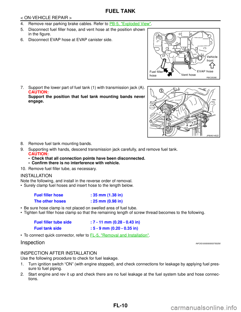
4. Remove rear parking brake cables. Refer to PB-5, "Exploded View".
5. Disconnect fuel filler hose, and vent hose at the position shown
in the figure.
6. Disconnect EVAP hose at EVAP canister side.
7. Support the lower part of fuel tank (1) with transmission jack (A).
CAUTION:
Support the position that fuel tank mounting bands never
engage.
8. Remove fuel tank mounting bands.
9. Supporting with hands, descend transmission jack carefully, and remove fuel tank.
CAUTION:
Check that all connection points have been disconnected.
Confirm there is no interference with vehicle.
10. Remove fuel filler tube, as necessary.
INSTALLATION
Note the following, and install in the reverse order of removal.
Surely clamp fuel hoses and insert hose to the length below.
Be sure hose clamp is not placed on swelled area of fuel tube.
Tighten fuel filler hose clamp so that the remaining length of screw thread becomes to the following.
To connect quick connector, refer to FL-5, "
Removal and Installation".
InspectionINFOID:0000000003793256
INSPECTION AFTER INSTALLATION
Use the following procedure to check for fuel leakage.
1. Turn ignition switch “ON” (with engine stopped), and check connections for leakage by applying fuel pres-
sure to fuel piping.
2. Start engine and rev it up and check there are no fuel leakage at the fuel system tube and hose connec-
tions.
PBIC2528E
JPBIA0145ZZ
Fuel filler hose : 35 mm (1.38 in)
The other hoses : 25 mm (0.98 in)
Fuel filler tube side : 7 - 11 mm (0.28 - 0.43 in)
Fuel tank side : 5 - 9 mm (0.20 - 0.35 in)
Page 2505 of 5121
GI-12
< HOW TO USE THIS MANUAL >
HOW TO READ WIRING DIAGRAMS
ignition switch is “OFF”,
doors, hood and trunk lid/back door are closed,
pedals are not depressed, and
parking brake is released.
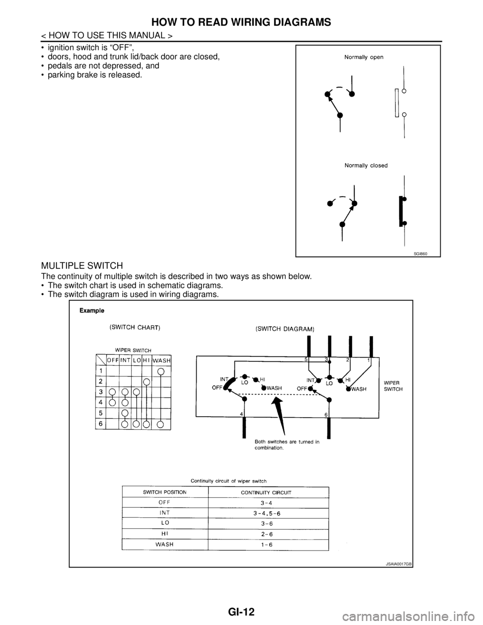
MULTIPLE SWITCH
The continuity of multiple switch is described in two ways as shown below.
The switch chart is used in schematic diagrams.
The switch diagram is used in wiring diagrams.
SGI860
JSAIA0017GB