Page 3277 of 5121
MWI
METER SYSTEM
MWI-23
< FUNCTION DIAGNOSIS >
C
D
E
F
G
H
I
J
K
L
MB A
O
P
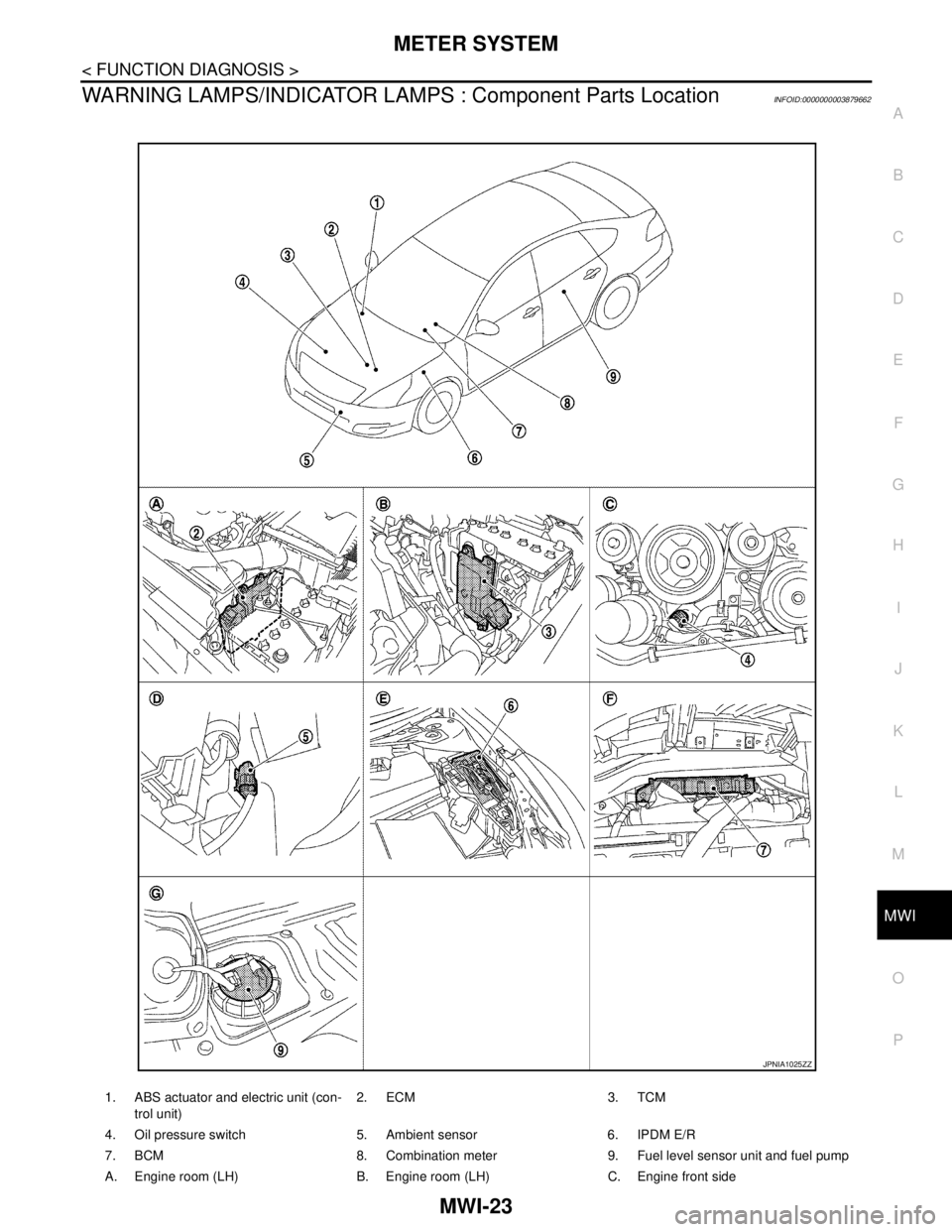
WARNING LAMPS/INDICATOR LAMPS : Component Parts LocationINFOID:0000000003879662
1. ABS actuator and electric unit (con-
trol unit)2. ECM 3. TCM
4. Oil pressure switch 5. Ambient sensor 6. IPDM E/R
7. BCM 8. Combination meter 9. Fuel level sensor unit and fuel pump
A. Engine room (LH) B. Engine room (LH) C. Engine front side
JPNIA1025ZZ
Page 3280 of 5121
MWI-26
< FUNCTION DIAGNOSIS >
METER SYSTEM
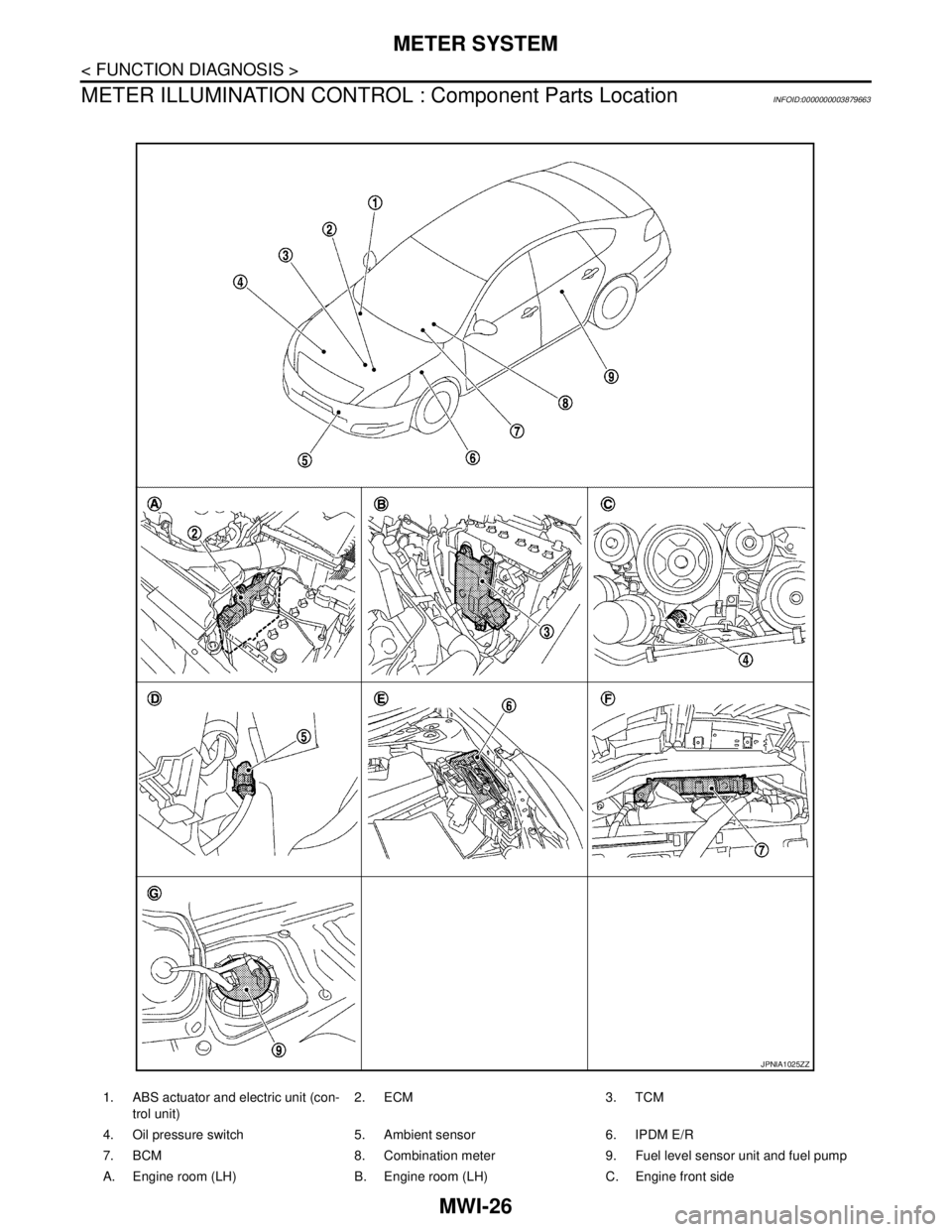
METER ILLUMINATION CONTROL : Component Parts Location
INFOID:0000000003879663
1. ABS actuator and electric unit (con-
trol unit)2. ECM 3. TCM
4. Oil pressure switch 5. Ambient sensor 6. IPDM E/R
7. BCM 8. Combination meter 9. Fuel level sensor unit and fuel pump
A. Engine room (LH) B. Engine room (LH) C. Engine front side
JPNIA1025ZZ
Page 3284 of 5121
MWI-30
< FUNCTION DIAGNOSIS >
METER SYSTEM
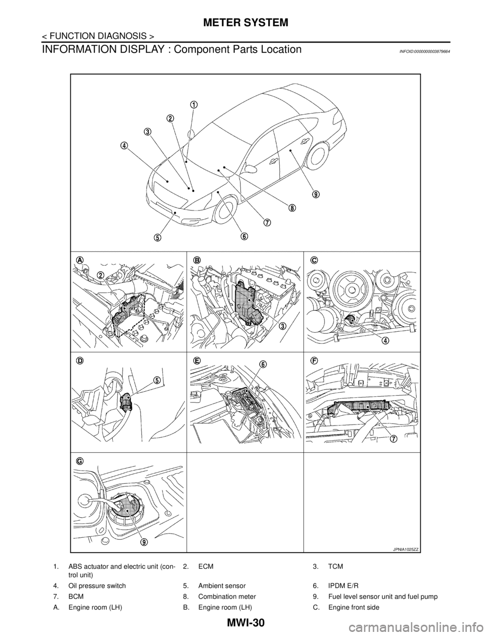
INFORMATION DISPLAY : Component Parts Location
INFOID:0000000003879664
1. ABS actuator and electric unit (con-
trol unit)2. ECM 3. TCM
4. Oil pressure switch 5. Ambient sensor 6. IPDM E/R
7. BCM 8. Combination meter 9. Fuel level sensor unit and fuel pump
A. Engine room (LH) B. Engine room (LH) C. Engine front side
JPNIA1025ZZ
Page 3299 of 5121
MWI
FUEL LEVEL SENSOR SIGNAL CIRCUIT
MWI-45
< COMPONENT DIAGNOSIS >
C
D
E
F
G
H
I
J
K
L
MB A
O
P
FUEL LEVEL SENSOR SIGNAL CIRCUIT
DescriptionINFOID:0000000003792570
The fuel level sensor unit and fuel pump detect the fuel level in the fuel tank and transmit the fuel gauge signal
to the combination meter.
Component Function CheckINFOID:0000000003792571
1.CHECK COMBINATION METER OUTPUT SIGNAL
Select the “Data Monitor” for the “METER/M&A” and compare the “FUEL METER” monitor value with the fuel
gauge reading on the combination meter.
Does monitor value match fuel gauge reading?
YES >> INSPECTION END
NO >> Replace combination meter.
Diagnosis ProcedureINFOID:0000000003792572
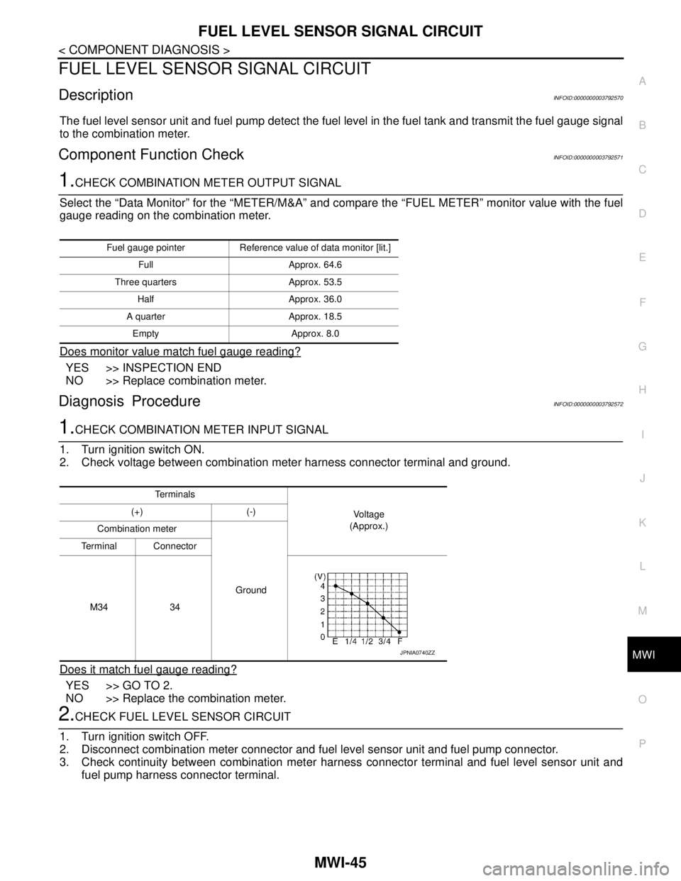
1.CHECK COMBINATION METER INPUT SIGNAL
1. Turn ignition switch ON.
2. Check voltage between combination meter harness connector terminal and ground.
Does it match fuel gauge reading?
YES >> GO TO 2.
NO >> Replace the combination meter.
2.CHECK FUEL LEVEL SENSOR CIRCUIT
1. Turn ignition switch OFF.
2. Disconnect combination meter connector and fuel level sensor unit and fuel pump connector.
3. Check continuity between combination meter harness connector terminal and fuel level sensor unit and
fuel pump harness connector terminal.
Fuel gauge pointer Reference value of data monitor [lit.]
Full Approx. 64.6
Three quarters Approx. 53.5
Half Approx. 36.0
A quarter Approx. 18.5
Empty Approx. 8.0
Te r m i n a l s
Vo l ta g e
(Approx.) (+) (-)
Combination meter
Ground Terminal Connector
M34 34
JPNIA0740ZZ
Page 3300 of 5121
MWI-46
< COMPONENT DIAGNOSIS >
FUEL LEVEL SENSOR SIGNAL CIRCUIT
4. Check continuity between combination meter harness connector terminal and ground.
Is the inspection result normal?
YES >> GO TO 3.
NO >> Repair harness or connector.
3.CHECK FUEL LEVEL SENSOR GROUND CIRCUIT
Check continuity between fuel level sensor unit and fuel pump harness connector terminal and combination
meter harness connector terminal.
Is the inspection result normal?
YES >> INSPECTION END
NO >> Repair harness or connector.
Component InspectionINFOID:0000000003792573
1.REMOVE FUEL LEVEL SENSOR UNIT
Remove the fuel level sensor unit. Refer to FL-5, "
Removal and Installation".
>> GO TO 2.
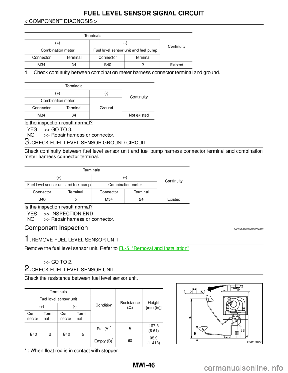
2.CHECK FUEL LEVEL SENSOR UNIT
Check the resistance between fuel level sensor unit.
* : When float rod is in contact with stopper.
Te r m i n a l s
Continuity (+) (-)
Combination meter Fuel level sensor unit and fuel pump
Connector Terminal Connector Terminal
M34 34 B40 2 Existed
Te r m i n a l s
Continuity (+) (-)
Combination meter
Ground Connector Terminal
M34 34 Not existed
Te r m i n a l s
Continuity (+) (-)
Fuel level sensor unit and fuel pump Combination meter
Connector Terminal Connector Terminal
B40 5 M34 24 Existed
Te r m i n a l s
ConditionResistance
(Ω)Height
[mm (in)] Fuel level sensor unit
(+) (-)
Con-
nectorTe r m i -
nalCon-
nectorTe r m i -
nal
B402B405Full (A)
*6167.8
(6.61)
Empty (B)
*8035.9
(1.413)JPNIA1018ZZ
Page 3359 of 5121
MWI
IPDM E/R (INTELLIGENT POWER DISTRIBUTION MODULE ENGINE ROOM)
MWI-105
< ECU DIAGNOSIS >
C
D
E
F
G
H
I
J
K
L
MB A
O
P
11
(P)GroundSteering lock unit power
supplyOutputIgnition
switch
OFFA few seconds after open-
ing the driver doorBattery voltage
Ignition
switch
LOCKPress the push-button ig-
nition switchBattery voltage
Ignition switch ACC or ON 0 V
12
(B/W)Ground Ground — Ignition switch ON 0 V
13
(SB)Ground Fuel pump power supply OutputApproximately 1 second or more after
turning the ignition switch ON0 V
Approximately 1 second after turning
the ignition switch ON
Engine runningBattery voltage
15
(W)Ground Ignition relay power supply OutputIgnition switch OFF 0 V
Ignition switch ON Battery voltage
16
(R)Ground Front wiper auto stop InputIgnition
switch ONFront wiper stop position 0 V
Any position other than
front wiper stop positionBattery voltage
17
(V)GroundHeadlamp washer relay
controlInputIgnition
switch ONHeadlamp washer deacti-
vatedBattery voltage
Headlamp washer activat-
ed0 V
19
(Y)Ground Ignition relay power supply OutputIgnition switch OFF 0 V
Ignition switch ON Battery voltage
20
(B)Ground Ambient sensor ground Output Ignition switch ON 0 V
21
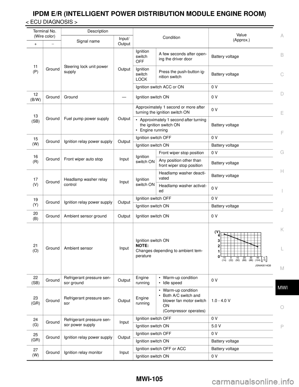
(O)Ground Ambient sensor InputIgnition switch ON
NOTE:
Changes depending to ambient tem-
perature
22
(SB)GroundRefrigerant pressure sen-
sor groundOutputEngine
running Warm-up condition
Idle speed0 V
23
(GR)GroundRefrigerant pressure sen-
sorOutputEngine
running Warm-up condition
Both A/C switch and
blower fan motor switch
ON
(Compressor operates)1.0 - 4.0 V
24
(G)
GroundRefrigerant pressure sen-
sor power supplyInputIgnition switch OFF 0 V
Ignition switch ON 5.0 V
25
(GR)Ground Ignition relay power supply OutputIgnition switch OFF 0 V
Ignition switch ON Battery voltage
27
(W)Ground Ignition relay monitor InputIgnition switch OFF or ACC Battery voltage
Ignition switch ON 0 V Te r m i n a l N o .
(Wire color)Description
ConditionVa l u e
(Approx.)
Signal nameInput/
Output +−
JSNIA0014GB
Page 3362 of 5121
MWI-108
< ECU DIAGNOSIS >
IPDM E/R (INTELLIGENT POWER DISTRIBUTION MODULE ENGINE ROOM)
75
(P/L)Ground Oil pressure switch InputIgnition
switch ONEngine stopped 0 V
Engine running Battery voltage
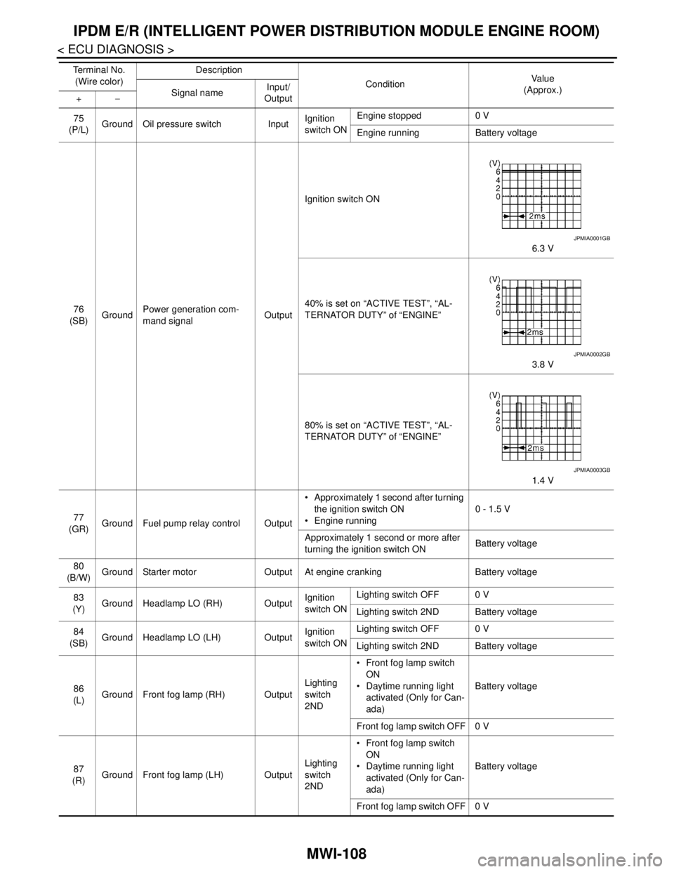
76
(SB)GroundPower generation com-
mand signalOutputIgnition switch ON
6.3 V
40% is set on “ACTIVE TEST”, “AL-
TERNATOR DUTY” of “ENGINE”
3.8 V
80% is set on “ACTIVE TEST”, “AL-
TERNATOR DUTY” of “ENGINE”
1.4 V
77
(GR)Ground Fuel pump relay control Output Approximately 1 second after turning
the ignition switch ON
Engine running0 - 1.5 V
Approximately 1 second or more after
turning the ignition switch ONBattery voltage
80
(B/W)Ground Starter motor Output At engine cranking Battery voltage
83
(Y)Ground Headlamp LO (RH) OutputIgnition
switch ONLighting switch OFF 0 V
Lighting switch 2ND Battery voltage
84
(SB)Ground Headlamp LO (LH) OutputIgnition
switch ONLighting switch OFF 0 V
Lighting switch 2ND Battery voltage
86
(L)Ground Front fog lamp (RH) OutputLighting
switch
2ND Front fog lamp switch
ON
Daytime running light
activated (Only for Can-
ada)Battery voltage
Front fog lamp switch OFF 0 V
87
(R)Ground Front fog lamp (LH) OutputLighting
switch
2ND Front fog lamp switch
ON
Daytime running light
activated (Only for Can-
ada)Battery voltage
Front fog lamp switch OFF 0 V Te r m i n a l N o .
(Wire color)Description
ConditionVa l u e
(Approx.)
Signal nameInput/
Output +−
JPMIA0001GB
JPMIA0002GB
JPMIA0003GB
Page 3414 of 5121
![NISSAN TEANA 2008 Service Manual PCS
IPDM E/R (INTELLIGENT POWER DISTRIBUTION MODULE ENGINE ROOM)
PCS-23
< ECU DIAGNOSIS >[IPDM E/R]
C
D
E
F
G
H
I
J
K
L B A
O
P N
11
(P)GroundSteering lock unit power
supplyOutputIgnition
switch
OF](/manual-img/5/57391/w960_57391-3413.png "NISSAN TEANA 2008 Service Manual PCS
IPDM E/R (INTELLIGENT POWER DISTRIBUTION MODULE ENGINE ROOM)
PCS-23
< ECU DIAGNOSIS >[IPDM E/R]
C
D
E
F
G
H
I
J
K
L B A
O
P N
11
(P)GroundSteering lock unit power
supplyOutputIgnition
switch
OF")
PCS
IPDM E/R (INTELLIGENT POWER DISTRIBUTION MODULE ENGINE ROOM)
PCS-23
< ECU DIAGNOSIS >[IPDM E/R]
C
D
E
F
G
H
I
J
K
L B A
O
P N
11
(P)GroundSteering lock unit power
supplyOutputIgnition
switch
OFFA few seconds after open-
ing the driver doorBattery voltage
Ignition
switch
LOCKPress the push-button ig-
nition switchBattery voltage
Ignition switch ACC or ON 0 V
12
(B/W)Ground Ground — Ignition switch ON 0 V
13
(SB)Ground Fuel pump power supply OutputApproximately 1 second or more after
turning the ignition switch ON0 V
Approximately 1 second after turning
the ignition switch ON
Engine runningBattery voltage
15
(W)Ground Ignition relay power supply OutputIgnition switch OFF 0 V
Ignition switch ON Battery voltage
16
(R)Ground Front wiper auto stop InputIgnition
switch ONFront wiper stop position 0 V
Any position other than
front wiper stop positionBattery voltage
17
(V)GroundHeadlamp washer relay
controlInputIgnition
switch ONHeadlamp washer deacti-
vatedBattery voltage
Headlamp washer activat-
ed0 V
19
(Y)Ground Ignition relay power supply OutputIgnition switch OFF 0 V
Ignition switch ON Battery voltage
20
(B)Ground Ambient sensor ground Output Ignition switch ON 0 V
21
(O)Ground Ambient sensor InputIgnition switch ON
NOTE:
Changes depending to ambient tem-
perature
22
(SB)GroundRefrigerant pressure sen-
sor groundOutputEngine
running Warm-up condition
Idle speed0 V
23
(GR)GroundRefrigerant pressure sen-
sorOutputEngine
running Warm-up condition
Both A/C switch and
blower fan motor switch
ON
(Compressor operates)1.0 - 4.0 V
24
(G)
GroundRefrigerant pressure sen-
sor power supplyInputIgnition switch OFF 0 V
Ignition switch ON 5.0 V
25
(GR)Ground Ignition relay power supply OutputIgnition switch OFF 0 V
Ignition switch ON Battery voltage
27
(W)Ground Ignition relay monitor InputIgnition switch OFF or ACC Battery voltage
Ignition switch ON 0 V Te r m i n a l N o .
(Wire color)Description
ConditionVa l u e
(Approx.)
Signal nameInput/
Output +−
JSNIA0014GB