2008 NISSAN TEANA fuel pump
[x] Cancel search: fuel pumpPage 1869 of 5121
![NISSAN TEANA 2008 Service Manual EC-408
< PRECAUTION >[VQ25DE, VQ35DE]
PRECAUTIONS
When measuring ECM signals with a circuit tester, never allow
the two tester probes to contact.
Accidental contact of probes will cause a short circu](/manual-img/5/57391/w960_57391-1868.png "NISSAN TEANA 2008 Service Manual EC-408
< PRECAUTION >[VQ25DE, VQ35DE]
PRECAUTIONS
When measuring ECM signals with a circuit tester, never allow
the two tester probes to contact.
Accidental contact of probes will cause a short circu")
EC-408
< PRECAUTION >[VQ25DE, VQ35DE]
PRECAUTIONS
When measuring ECM signals with a circuit tester, never allow
the two tester probes to contact.
Accidental contact of probes will cause a short circuit and
damage the ECM power transistor.
Never use ECM ground terminals when measuring input/out-
put voltage. Doing so may result in damage to the ECM's tran-
sistor. Use a ground other than ECM terminals, such as the
ground.
B1 indicates bank 1, B2 indicates bank 2 as shown in the fig-
ure.
Never operate fuel pump when there is no fuel in lines.
Tighten fuel hose clamps to the specified torque.
Never depress accelerator pedal when starting.
Immediately after starting, never rev up engine unnecessarily.
Never rev up engine just prior to shutdown.
SEF348N
SEC893C
SEF709Y
Page 1872 of 5121
![NISSAN TEANA 2008 Service Manual FUEL PRESSURE
EC-411
< ON-VEHICLE MAINTENANCE >[VQ25DE, VQ35DE]
C
D
E
F
G
H
I
J
K
L
MA
EC
N
P O
ON-VEHICLE MAINTENANCE
FUEL PRESSURE
InspectionINFOID:0000000003856884
FUEL PRESSURE RELEASE
With CONSU](/manual-img/5/57391/w960_57391-1871.png "NISSAN TEANA 2008 Service Manual FUEL PRESSURE
EC-411
< ON-VEHICLE MAINTENANCE >[VQ25DE, VQ35DE]
C
D
E
F
G
H
I
J
K
L
MA
EC
N
P O
ON-VEHICLE MAINTENANCE
FUEL PRESSURE
InspectionINFOID:0000000003856884
FUEL PRESSURE RELEASE
With CONSU")
FUEL PRESSURE
EC-411
< ON-VEHICLE MAINTENANCE >[VQ25DE, VQ35DE]
C
D
E
F
G
H
I
J
K
L
MA
EC
N
P O
ON-VEHICLE MAINTENANCE
FUEL PRESSURE
InspectionINFOID:0000000003856884
FUEL PRESSURE RELEASE
With CONSULT-III
1. Turn ignition switch ON.
2. Perform “FUEL PRESSURE RELEASE” in “WORK SUPPORT” mode with CONSULT-III.
3. Start engine.
4. After engine stalls, crank it 2 or 3 times to release all fuel pressure.
5. Turn ignition switch OFF.
Without CONSULT-III
1. Remove fuel pump fuse located in IPDM E/R.
2. Start engine.
3. After engine stalls, crank it 2 or 3 times to release all fuel pressure.
4. Turn ignition switch OFF.
5. Reinstall fuel pump fuse after servicing fuel system.
FUEL PRESSURE CHECK
CAUTION:
Before disconnecting fuel line, release fuel pressure from fuel line to eliminate danger.
NOTE:
Prepare pans or saucers under the disconnected fuel line because the fuel may spill out. The fuel
pressure cannot be completely released because J32 models do not have fuel return system.
Be careful not to scratch or get the fuel hose connection area dirty when servicing, so that the quick
connector o-ring maintains seal ability.
1. Release fuel pressure to zero.
2. Remove fuel hose using Quick Connector Release.
Do not twist or kink fuel hose because it is plastic hose.
Keep fuel hose connections clean.
3. Install Fuel pressure adapter (B) and Fuel pressure gauge (A)
as shown in figure.
Do not distort or bend fuel rail tube when installing fuel pres-
sure gauge adapter.
When reconnecting fuel hose, check the original fuel hose for
damage and abnormality.
4. Turn ignition switch ON (reactivate fuel pump) and check for fuel
leakage.
5. Start engine and check for fuel leakage.
6. Read the indication of fuel pressure gauge kit.
During fuel pressure check, check for fuel leakage from fuel
connection every 3 minutes.
7. If result is unsatisfactory, go to next step.
8. Check the following.
Fuel hoses and fuel tubes for clogging
Fuel filter for clogging
Fuel pump
Fuel pressure regulator for clogging
9. If OK, replace fuel pressure regulator.
If NG, repair or replace malfunctioning part.
At idling
: Approximately 350 kPa (3.5 bar, 3.57 kg/cm2, 51 psi)
JMBIA1392ZZ
Page 1897 of 5121
EM-22
< ON-VEHICLE MAINTENANCE >
COMPRESSION PRESSURE
COMPRESSION PRESSURE
InspectionINFOID:0000000003802245
1. Warm up engine thoroughly. Then, stop it.
2. Release fuel pressure. Refer to EC-411, "
Inspection".
3. Disconnect fuel pump fuse to avoid fuel injection during measurement. Refer to EC-20,
"ComponentPartsLocation".
4. Remove engine cover. Refer to EM-24, "
Exploded View".
5. Remove ignition coil and spark plug from each cylinder. Refer to EM-49, "
Exploded View".
6. Connect engine tachometer (not required in use of CONSULT-III).
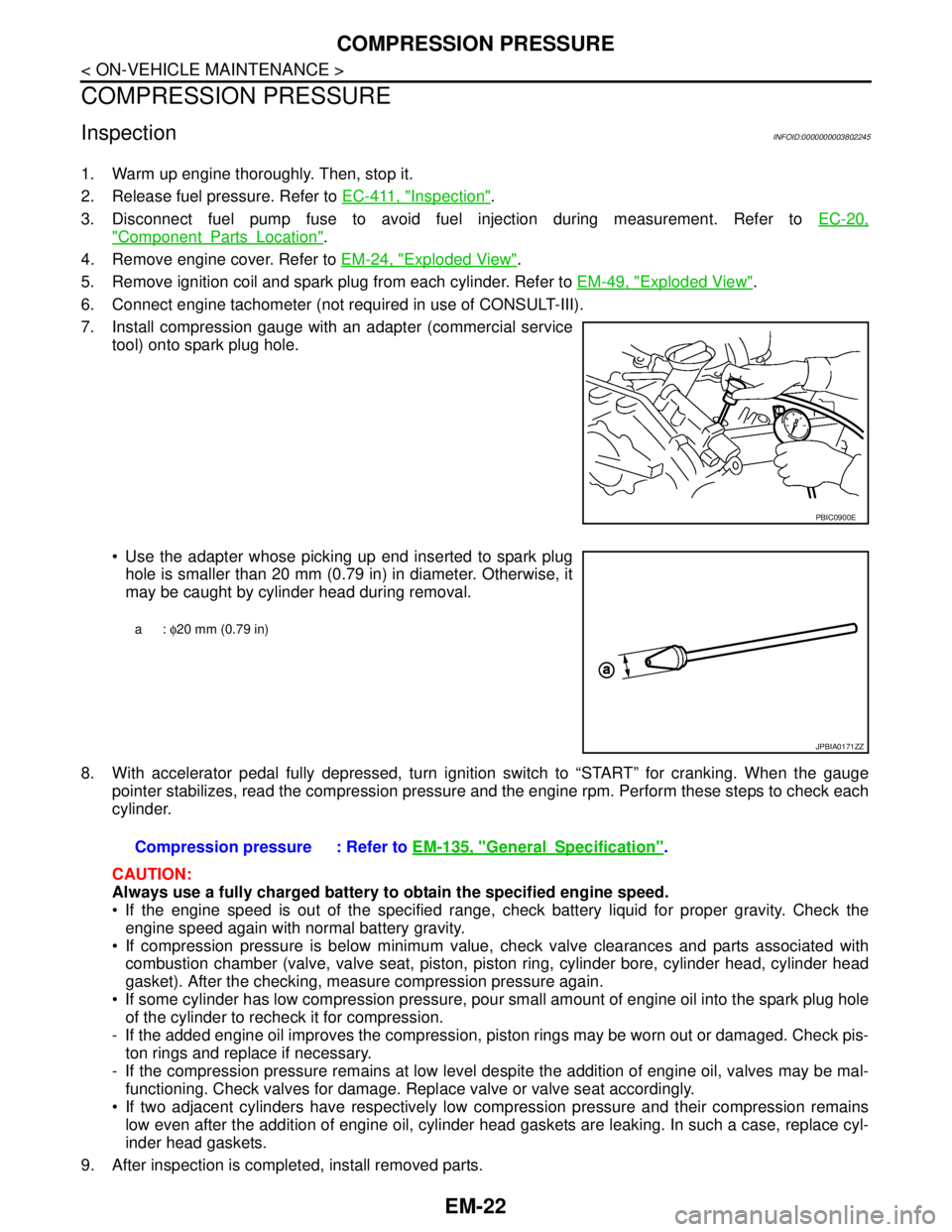
7. Install compression gauge with an adapter (commercial service
tool) onto spark plug hole.
Use the adapter whose picking up end inserted to spark plug
hole is smaller than 20 mm (0.79 in) in diameter. Otherwise, it
may be caught by cylinder head during removal.
8. With accelerator pedal fully depressed, turn ignition switch to “START” for cranking. When the gauge
pointer stabilizes, read the compression pressure and the engine rpm. Perform these steps to check each
cylinder.
CAUTION:
Always use a fully charged battery to obtain the specified engine speed.
If the engine speed is out of the specified range, check battery liquid for proper gravity. Check the
engine speed again with normal battery gravity.
If compression pressure is below minimum value, check valve clearances and parts associated with
combustion chamber (valve, valve seat, piston, piston ring, cylinder bore, cylinder head, cylinder head
gasket). After the checking, measure compression pressure again.
If some cylinder has low compression pressure, pour small amount of engine oil into the spark plug hole
of the cylinder to recheck it for compression.
- If the added engine oil improves the compression, piston rings may be worn out or damaged. Check pis-
ton rings and replace if necessary.
- If the compression pressure remains at low level despite the addition of engine oil, valves may be mal-
functioning. Check valves for damage. Replace valve or valve seat accordingly.
If two adjacent cylinders have respectively low compression pressure and their compression remains
low even after the addition of engine oil, cylinder head gaskets are leaking. In such a case, replace cyl-
inder head gaskets.
9. After inspection is completed, install removed parts.
PBIC0900E
a: φ20 mm (0.79 in)
JPBIA0171ZZ
Compression pressure : Refer to EM-135, "GeneralSpecification".
Page 1943 of 5121
EM-68
< REMOVAL AND INSTALLATION >
ENGINE ASSEMBLY
Place chocks at front and back of rear wheels.
For engines not equipped with engine slingers, attach proper slingers and bolts described in PARTS
CATALOG.
CAUTION:
Always be careful to work safely, avoid forceful or uninstructed operations.
Never start working until exhaust system and engine coolant are cool enough.
If items or work required are not covered by the engine section, refer to the applicable sections.
Always use the support point specified for lifting.
Use either 2-pole lift type or separate type lift as best you can. If board-on type is used for unavoid-
able reasons, support at the rear axle jacking point with transmission jack or similar tool before
starting work, in preparation for the backward shift of center of gravity.
For supporting points for lifting and jacking point at rear axle, refer to GI-30, "
Garage Jack and
Safety Stand and 2-Pole Lift".
REMOVAL
Outline
At first, remove the engine and the transaxle assembly with front suspension member downward. Then sepa-
rate the engine and the transaxle.
Preparation
1. Release fuel pressure. Refer to EC-411, "Inspection".
2. Drain engine coolant. Refer to CO-8, "
Draining".
CAUTION:
Perform this step when the engine is cold.
Never spill engine coolant on drive belt.
3. Remove the following parts:
Engine cover: Refer to EM-24, "
Exploded View".
Front road wheel and tires
Splash guards (RH and LH): Refer to EXT-22, "
FENDER PROTECTOR : Exploded View".
Air duct (inlet), air cleaner cases (upper and lower) with mass air flow sensor and air duct assembly:
Refer to EM-26, "
Exploded View".
Battery and battery tray: Refer to PG-109, "
Removal and Installation".
Drive belt: Refer to EM-12, "
Removal and Installation".
Reservoir tank of radiator. Refer to CO-13, "
Exploded View".
Front wiper arm: Refer to WW-105, "
Exploded View".
4. Disconnect engine room harness at the TCM, ECM and other sides.
CAUTION:
To keep clean harness connector and avoid damage and foreign materials, cover them completely
with plastic bags or something similar.
5. Remove battery bracket with ECM and TCM.
6. Remove extension cowl top. Refer to EXT-20, "
Exploded View".
Engine Room
1. Disconnect heater hoses. Refer to CO-25, "Exploded View".
Install plug to avoid leakage of engine coolant.
2. Remove EVAP hose. Refer to EM-28, "
Exploded View".
3. Disconnect fuel feed hose quick connector at fuel tube side. Refer to EM-44, "
Exploded View".
Install plug to avoid leakage of fuel.
4. Disconnect transaxle shift control cable at transaxle side. Refer to TM-319, "
Exploded View" (VQ25DE) or
TM-157, "
Exploded View" (VQ35DE).
5. Disconnect brake booster vacuum hose at engine side. Refer to EM-28, "
Exploded View".
6. Disconnect ground cable.
7. Disconnect A/C compressor piping at A/C compressor side. Refer to HA-36, "
Exploded View".
8. Disconnect suction hoses of power steering oil pump at reservoir tank side. Refer to ST-34, "
Exploded
View".
Install plug to avoid leakage of power steering fluid.
9. Disconnect CVT fluid cooler hoses from radiator. Refer to CO-13, "
Exploded View".
Page 2174 of 5121
![NISSAN TEANA 2008 Service Manual IPDM E/R (INTELLIGENT POWER DISTRIBUTION MODULE ENGINE ROOM)
EXL-145
< ECU DIAGNOSIS >[XENON TYPE]
C
D
E
F
G
H
I
J
K
MA
B
EXL
N
O
P
11
(P)GroundSteering lock unit power
supplyOutputIgnition
switch](/manual-img/5/57391/w960_57391-2173.png "NISSAN TEANA 2008 Service Manual IPDM E/R (INTELLIGENT POWER DISTRIBUTION MODULE ENGINE ROOM)
EXL-145
< ECU DIAGNOSIS >[XENON TYPE]
C
D
E
F
G
H
I
J
K
MA
B
EXL
N
O
P
11
(P)GroundSteering lock unit power
supplyOutputIgnition
switch")
IPDM E/R (INTELLIGENT POWER DISTRIBUTION MODULE ENGINE ROOM)
EXL-145
< ECU DIAGNOSIS >[XENON TYPE]
C
D
E
F
G
H
I
J
K
MA
B
EXL
N
O
P
11
(P)GroundSteering lock unit power
supplyOutputIgnition
switch
OFFA few seconds after open-
ing the driver doorBattery voltage
Ignition
switch
LOCKPress the push-button ig-
nition switchBattery voltage
Ignition switch ACC or ON 0 V
12
(B/W)Ground Ground — Ignition switch ON 0 V
13
(SB)Ground Fuel pump power supply OutputApproximately 1 second or more after
turning the ignition switch ON0 V
Approximately 1 second after turning
the ignition switch ON
Engine runningBattery voltage
15
(W)Ground Ignition relay power supply OutputIgnition switch OFF 0 V
Ignition switch ON Battery voltage
16
(R)Ground Front wiper auto stop InputIgnition
switch ONFront wiper stop position 0 V
Any position other than
front wiper stop positionBattery voltage
17
(V)GroundHeadlamp washer relay
controlInputIgnition
switch ONHeadlamp washer deacti-
vatedBattery voltage
Headlamp washer activat-
ed0 V
19
(Y)Ground Ignition relay power supply OutputIgnition switch OFF 0 V
Ignition switch ON Battery voltage
20
(B)Ground Ambient sensor ground Output Ignition switch ON 0 V
21
(O)Ground Ambient sensor InputIgnition switch ON
NOTE:
Changes depending to ambient tem-
perature
22
(SB)GroundRefrigerant pressure sen-
sor groundOutputEngine
running Warm-up condition
Idle speed0 V
23
(GR)GroundRefrigerant pressure sen-
sorOutputEngine
running Warm-up condition
Both A/C switch and
blower fan motor switch
ON
(Compressor operates)1.0 - 4.0 V
24
(G)
GroundRefrigerant pressure sen-
sor power supplyInputIgnition switch OFF 0 V
Ignition switch ON 5.0 V
25
(GR)Ground Ignition relay power supply OutputIgnition switch OFF 0 V
Ignition switch ON Battery voltage
27
(W)Ground Ignition relay monitor InputIgnition switch OFF or ACC Battery voltage
Ignition switch ON 0 V Te r m i n a l N o .
(Wire color)Description
ConditionVa l u e
(Approx.)
Signal nameInput/
Output +−
JSNIA0014GB
Page 2177 of 5121
![NISSAN TEANA 2008 Service Manual EXL-148
< ECU DIAGNOSIS >[XENON TYPE]
IPDM E/R (INTELLIGENT POWER DISTRIBUTION MODULE ENGINE ROOM)
75
(P/L)Ground Oil pressure switch InputIgnition
switch ONEngine stopped 0 V
Engine running Battery](/manual-img/5/57391/w960_57391-2176.png "NISSAN TEANA 2008 Service Manual EXL-148
< ECU DIAGNOSIS >[XENON TYPE]
IPDM E/R (INTELLIGENT POWER DISTRIBUTION MODULE ENGINE ROOM)
75
(P/L)Ground Oil pressure switch InputIgnition
switch ONEngine stopped 0 V
Engine running Battery")
EXL-148
< ECU DIAGNOSIS >[XENON TYPE]
IPDM E/R (INTELLIGENT POWER DISTRIBUTION MODULE ENGINE ROOM)
75
(P/L)Ground Oil pressure switch InputIgnition
switch ONEngine stopped 0 V
Engine running Battery voltage
76
(SB)GroundPower generation com-
mand signalOutputIgnition switch ON
6.3 V
40% is set on “ACTIVE TEST”, “AL-
TERNATOR DUTY” of “ENGINE”
3.8 V
80% is set on “ACTIVE TEST”, “AL-
TERNATOR DUTY” of “ENGINE”
1.4 V
77
(GR)Ground Fuel pump relay control Output Approximately 1 second after turning
the ignition switch ON
Engine running0 - 1.5 V
Approximately 1 second or more after
turning the ignition switch ONBattery voltage
80
(B/W)Ground Starter motor Output At engine cranking Battery voltage
83
(Y)Ground Headlamp LO (RH) OutputIgnition
switch ONLighting switch OFF 0 V
Lighting switch 2ND Battery voltage
84
(SB)Ground Headlamp LO (LH) OutputIgnition
switch ONLighting switch OFF 0 V
Lighting switch 2ND Battery voltage
86
(L)Ground Front fog lamp (RH) OutputLighting
switch
2ND Front fog lamp switch
ON
Daytime running light
activated (Only for Can-
ada)Battery voltage
Front fog lamp switch OFF 0 V
87
(R)Ground Front fog lamp (LH) OutputLighting
switch
2ND Front fog lamp switch
ON
Daytime running light
activated (Only for Can-
ada)Battery voltage
Front fog lamp switch OFF 0 V Te r m i n a l N o .
(Wire color)Description
ConditionVa l u e
(Approx.)
Signal nameInput/
Output +−
JPMIA0001GB
JPMIA0002GB
JPMIA0003GB
Page 2346 of 5121
![NISSAN TEANA 2008 Service Manual IPDM E/R (INTELLIGENT POWER DISTRIBUTION MODULE ENGINE ROOM)
EXL-317
< ECU DIAGNOSIS >[HALOGEN TYPE]
C
D
E
F
G
H
I
J
K
MA
B
EXL
N
O
P
11
(P)GroundSteering lock unit power
supplyOutputIgnition
switch](/manual-img/5/57391/w960_57391-2345.png "NISSAN TEANA 2008 Service Manual IPDM E/R (INTELLIGENT POWER DISTRIBUTION MODULE ENGINE ROOM)
EXL-317
< ECU DIAGNOSIS >[HALOGEN TYPE]
C
D
E
F
G
H
I
J
K
MA
B
EXL
N
O
P
11
(P)GroundSteering lock unit power
supplyOutputIgnition
switch")
IPDM E/R (INTELLIGENT POWER DISTRIBUTION MODULE ENGINE ROOM)
EXL-317
< ECU DIAGNOSIS >[HALOGEN TYPE]
C
D
E
F
G
H
I
J
K
MA
B
EXL
N
O
P
11
(P)GroundSteering lock unit power
supplyOutputIgnition
switch
OFFA few seconds after open-
ing the driver doorBattery voltage
Ignition
switch
LOCKPress the push-button ig-
nition switchBattery voltage
Ignition switch ACC or ON 0 V
12
(B/W)Ground Ground — Ignition switch ON 0 V
13
(SB)Ground Fuel pump power supply OutputApproximately 1 second or more after
turning the ignition switch ON0 V
Approximately 1 second after turning
the ignition switch ON
Engine runningBattery voltage
15
(W)Ground Ignition relay power supply OutputIgnition switch OFF 0 V
Ignition switch ON Battery voltage
16
(R)Ground Front wiper auto stop InputIgnition
switch ONFront wiper stop position 0 V
Any position other than
front wiper stop positionBattery voltage
17
(V)GroundHeadlamp washer relay
controlInputIgnition
switch ONHeadlamp washer deacti-
vatedBattery voltage
Headlamp washer activat-
ed0 V
19
(Y)Ground Ignition relay power supply OutputIgnition switch OFF 0 V
Ignition switch ON Battery voltage
20
(B)Ground Ambient sensor ground Output Ignition switch ON 0 V
21
(O)Ground Ambient sensor InputIgnition switch ON
NOTE:
Changes depending to ambient tem-
perature
22
(SB)GroundRefrigerant pressure sen-
sor groundOutputEngine
running Warm-up condition
Idle speed0 V
23
(GR)GroundRefrigerant pressure sen-
sorOutputEngine
running Warm-up condition
Both A/C switch and
blower fan motor switch
ON
(Compressor operates)1.0 - 4.0 V
24
(G)
GroundRefrigerant pressure sen-
sor power supplyInputIgnition switch OFF 0 V
Ignition switch ON 5.0 V
25
(GR)Ground Ignition relay power supply OutputIgnition switch OFF 0 V
Ignition switch ON Battery voltage
27
(W)Ground Ignition relay monitor InputIgnition switch OFF or ACC Battery voltage
Ignition switch ON 0 V Te r m i n a l N o .
(Wire color)Description
ConditionVa l u e
(Approx.)
Signal nameInput/
Output +−
JSNIA0014GB
Page 2349 of 5121
![NISSAN TEANA 2008 Service Manual EXL-320
< ECU DIAGNOSIS >[HALOGEN TYPE]
IPDM E/R (INTELLIGENT POWER DISTRIBUTION MODULE ENGINE ROOM)
75
(P/L)Ground Oil pressure switch InputIgnition
switch ONEngine stopped 0 V
Engine running Batter](/manual-img/5/57391/w960_57391-2348.png "NISSAN TEANA 2008 Service Manual EXL-320
< ECU DIAGNOSIS >[HALOGEN TYPE]
IPDM E/R (INTELLIGENT POWER DISTRIBUTION MODULE ENGINE ROOM)
75
(P/L)Ground Oil pressure switch InputIgnition
switch ONEngine stopped 0 V
Engine running Batter")
EXL-320
< ECU DIAGNOSIS >[HALOGEN TYPE]
IPDM E/R (INTELLIGENT POWER DISTRIBUTION MODULE ENGINE ROOM)
75
(P/L)Ground Oil pressure switch InputIgnition
switch ONEngine stopped 0 V
Engine running Battery voltage
76
(SB)GroundPower generation com-
mand signalOutputIgnition switch ON
6.3 V
40% is set on “ACTIVE TEST”, “AL-
TERNATOR DUTY” of “ENGINE”
3.8 V
80% is set on “ACTIVE TEST”, “AL-
TERNATOR DUTY” of “ENGINE”
1.4 V
77
(GR)Ground Fuel pump relay control Output Approximately 1 second after turning
the ignition switch ON
Engine running0 - 1.5 V
Approximately 1 second or more after
turning the ignition switch ONBattery voltage
80
(B/W)Ground Starter motor Output At engine cranking Battery voltage
83
(Y)Ground Headlamp LO (RH) OutputIgnition
switch ONLighting switch OFF 0 V
Lighting switch 2ND Battery voltage
84
(SB)Ground Headlamp LO (LH) OutputIgnition
switch ONLighting switch OFF 0 V
Lighting switch 2ND Battery voltage
86
(L)Ground Front fog lamp (RH) OutputLighting
switch
2ND Front fog lamp switch
ON
Daytime running light
activated (Only for Can-
ada)Battery voltage
Front fog lamp switch OFF 0 V
87
(R)Ground Front fog lamp (LH) OutputLighting
switch
2ND Front fog lamp switch
ON
Daytime running light
activated (Only for Can-
ada)Battery voltage
Front fog lamp switch OFF 0 V Te r m i n a l N o .
(Wire color)Description
ConditionVa l u e
(Approx.)
Signal nameInput/
Output +−
JPMIA0001GB
JPMIA0002GB
JPMIA0003GB