2008 NISSAN TEANA fuel pump
[x] Cancel search: fuel pumpPage 3417 of 5121
![NISSAN TEANA 2008 Service Manual PCS-26
< ECU DIAGNOSIS >[IPDM E/R]
IPDM E/R (INTELLIGENT POWER DISTRIBUTION MODULE ENGINE ROOM)
75
(P/L)Ground Oil pressure switch InputIgnition
switch ONEngine stopped 0 V
Engine running Battery vol](/manual-img/5/57391/w960_57391-3416.png "NISSAN TEANA 2008 Service Manual PCS-26
< ECU DIAGNOSIS >[IPDM E/R]
IPDM E/R (INTELLIGENT POWER DISTRIBUTION MODULE ENGINE ROOM)
75
(P/L)Ground Oil pressure switch InputIgnition
switch ONEngine stopped 0 V
Engine running Battery vol")
PCS-26
< ECU DIAGNOSIS >[IPDM E/R]
IPDM E/R (INTELLIGENT POWER DISTRIBUTION MODULE ENGINE ROOM)
75
(P/L)Ground Oil pressure switch InputIgnition
switch ONEngine stopped 0 V
Engine running Battery voltage
76
(SB)GroundPower generation com-
mand signalOutputIgnition switch ON
6.3 V
40% is set on “ACTIVE TEST”, “AL-
TERNATOR DUTY” of “ENGINE”
3.8 V
80% is set on “ACTIVE TEST”, “AL-
TERNATOR DUTY” of “ENGINE”
1.4 V
77
(GR)Ground Fuel pump relay control Output Approximately 1 second after turning
the ignition switch ON
Engine running0 - 1.5 V
Approximately 1 second or more after
turning the ignition switch ONBattery voltage
80
(B/W)Ground Starter motor Output At engine cranking Battery voltage
83
(Y)Ground Headlamp LO (RH) OutputIgnition
switch ONLighting switch OFF 0 V
Lighting switch 2ND Battery voltage
84
(SB)Ground Headlamp LO (LH) OutputIgnition
switch ONLighting switch OFF 0 V
Lighting switch 2ND Battery voltage
86
(L)Ground Front fog lamp (RH) OutputLighting
switch
2ND Front fog lamp switch
ON
Daytime running light
activated (Only for Can-
ada)Battery voltage
Front fog lamp switch OFF 0 V
87
(R)Ground Front fog lamp (LH) OutputLighting
switch
2ND Front fog lamp switch
ON
Daytime running light
activated (Only for Can-
ada)Battery voltage
Front fog lamp switch OFF 0 V Te r m i n a l N o .
(Wire color)Description
ConditionVa l u e
(Approx.)
Signal nameInput/
Output +−
JPMIA0001GB
JPMIA0002GB
JPMIA0003GB
Page 3501 of 5121
![NISSAN TEANA 2008 Service Manual PCS-110
< ECU DIAGNOSIS >[POWER DISTRIBUTION SYSTEM]
IPDM E/R (INTELLIGENT POWER DISTRIBUTION MODULE ENGINE ROOM)
11
(P)GroundSteering lock unit power
supplyOutputIgnition
switch
OFFA few seconds a](/manual-img/5/57391/w960_57391-3500.png "NISSAN TEANA 2008 Service Manual PCS-110
< ECU DIAGNOSIS >[POWER DISTRIBUTION SYSTEM]
IPDM E/R (INTELLIGENT POWER DISTRIBUTION MODULE ENGINE ROOM)
11
(P)GroundSteering lock unit power
supplyOutputIgnition
switch
OFFA few seconds a")
PCS-110
< ECU DIAGNOSIS >[POWER DISTRIBUTION SYSTEM]
IPDM E/R (INTELLIGENT POWER DISTRIBUTION MODULE ENGINE ROOM)
11
(P)GroundSteering lock unit power
supplyOutputIgnition
switch
OFFA few seconds after open-
ing the driver doorBattery voltage
Ignition
switch
LOCKPress the push-button ig-
nition switchBattery voltage
Ignition switch ACC or ON 0 V
12
(B/W)Ground Ground — Ignition switch ON 0 V
13
(SB)Ground Fuel pump power supply OutputApproximately 1 second or more after
turning the ignition switch ON0 V
Approximately 1 second after turning
the ignition switch ON
Engine runningBattery voltage
15
(W)Ground Ignition relay power supply OutputIgnition switch OFF 0 V
Ignition switch ON Battery voltage
16
(R)Ground Front wiper auto stop InputIgnition
switch ONFront wiper stop position 0 V
Any position other than
front wiper stop positionBattery voltage
17
(V)GroundHeadlamp washer relay
controlInputIgnition
switch ONHeadlamp washer deacti-
vatedBattery voltage
Headlamp washer activat-
ed0 V
19
(Y)Ground Ignition relay power supply OutputIgnition switch OFF 0 V
Ignition switch ON Battery voltage
20
(B)Ground Ambient sensor ground Output Ignition switch ON 0 V
21
(O)Ground Ambient sensor InputIgnition switch ON
NOTE:
Changes depending to ambient tem-
perature
22
(SB)GroundRefrigerant pressure sen-
sor groundOutputEngine
running Warm-up condition
Idle speed0 V
23
(GR)GroundRefrigerant pressure sen-
sorOutputEngine
running Warm-up condition
Both A/C switch and
blower fan motor switch
ON
(Compressor operates)1.0 - 4.0 V
24
(G)GroundRefrigerant pressure sen-
sor power supplyInputIgnition switch OFF 0 V
Ignition switch ON 5.0 V
25
(GR)Ground Ignition relay power supply OutputIgnition switch OFF 0 V
Ignition switch ON Battery voltage
27
(W)Ground Ignition relay monitor InputIgnition switch OFF or ACC Battery voltage
Ignition switch ON 0 V Te r m i n a l N o .
(Wire color)Description
ConditionVa l u e
(Approx.)
Signal nameInput/
Output +−
JSNIA0014GB
Page 3504 of 5121
![NISSAN TEANA 2008 Service Manual PCS
IPDM E/R (INTELLIGENT POWER DISTRIBUTION MODULE ENGINE ROOM)
PCS-113
< ECU DIAGNOSIS >[POWER DISTRIBUTION SYSTEM]
C
D
E
F
G
H
I
J
K
L B A
O
P N
75
(P/L)Ground Oil pressure switch InputIgnition
sw](/manual-img/5/57391/w960_57391-3503.png "NISSAN TEANA 2008 Service Manual PCS
IPDM E/R (INTELLIGENT POWER DISTRIBUTION MODULE ENGINE ROOM)
PCS-113
< ECU DIAGNOSIS >[POWER DISTRIBUTION SYSTEM]
C
D
E
F
G
H
I
J
K
L B A
O
P N
75
(P/L)Ground Oil pressure switch InputIgnition
sw")
PCS
IPDM E/R (INTELLIGENT POWER DISTRIBUTION MODULE ENGINE ROOM)
PCS-113
< ECU DIAGNOSIS >[POWER DISTRIBUTION SYSTEM]
C
D
E
F
G
H
I
J
K
L B A
O
P N
75
(P/L)Ground Oil pressure switch InputIgnition
switch ONEngine stopped 0 V
Engine running Battery voltage
76
(SB)GroundPower generation com-
mand signalOutputIgnition switch ON
6.3 V
40% is set on “ACTIVE TEST”, “AL-
TERNATOR DUTY” of “ENGINE”
3.8 V
80% is set on “ACTIVE TEST”, “AL-
TERNATOR DUTY” of “ENGINE”
1.4 V
77
(GR)Ground Fuel pump relay control Output Approximately 1 second after turning
the ignition switch ON
Engine running0 - 1.5 V
Approximately 1 second or more after
turning the ignition switch ONBattery voltage
80
(B/W)Ground Starter motor Output At engine cranking Battery voltage
83
(Y)Ground Headlamp LO (RH) OutputIgnition
switch ONLighting switch OFF 0 V
Lighting switch 2ND Battery voltage
84
(SB)Ground Headlamp LO (LH) OutputIgnition
switch ONLighting switch OFF 0 V
Lighting switch 2ND Battery voltage
86
(L)Ground Front fog lamp (RH) OutputLighting
switch
2ND Front fog lamp switch
ON
Daytime running light
activated (Only for Can-
ada)Battery voltage
Front fog lamp switch OFF 0 V
87
(R)Ground Front fog lamp (LH) OutputLighting
switch
2ND Front fog lamp switch
ON
Daytime running light
activated (Only for Can-
ada)Battery voltage
Front fog lamp switch OFF 0 V Te r m i n a l N o .
(Wire color)Description
ConditionVa l u e
(Approx.)
Signal nameInput/
Output +−
JPMIA0001GB
JPMIA0002GB
JPMIA0003GB
Page 4190 of 5121
![NISSAN TEANA 2008 Service Manual IPDM E/R (INTELLIGENT POWER DISTRIBUTION MODULE ENGINE ROOM)
SEC-181
< ECU DIAGNOSIS >[INTELLIGENT KEY SYSTEM]
C
D
E
F
G
H
I
J
L
MA
B
SEC
N
O
P
11
(P)GroundSteering lock unit power
supplyOutputIgniti](/manual-img/5/57391/w960_57391-4189.png "NISSAN TEANA 2008 Service Manual IPDM E/R (INTELLIGENT POWER DISTRIBUTION MODULE ENGINE ROOM)
SEC-181
< ECU DIAGNOSIS >[INTELLIGENT KEY SYSTEM]
C
D
E
F
G
H
I
J
L
MA
B
SEC
N
O
P
11
(P)GroundSteering lock unit power
supplyOutputIgniti")
IPDM E/R (INTELLIGENT POWER DISTRIBUTION MODULE ENGINE ROOM)
SEC-181
< ECU DIAGNOSIS >[INTELLIGENT KEY SYSTEM]
C
D
E
F
G
H
I
J
L
MA
B
SEC
N
O
P
11
(P)GroundSteering lock unit power
supplyOutputIgnition
switch
OFFA few seconds after open-
ing the driver doorBattery voltage
Ignition
switch
LOCKPress the push-button ig-
nition switchBattery voltage
Ignition switch ACC or ON 0 V
12
(B/W)Ground Ground — Ignition switch ON 0 V
13
(SB)Ground Fuel pump power supply OutputApproximately 1 second or more after
turning the ignition switch ON0 V
Approximately 1 second after turning
the ignition switch ON
Engine runningBattery voltage
15
(W)Ground Ignition relay power supply OutputIgnition switch OFF 0 V
Ignition switch ON Battery voltage
16
(R)Ground Front wiper auto stop InputIgnition
switch ONFront wiper stop position 0 V
Any position other than
front wiper stop positionBattery voltage
17
(V)GroundHeadlamp washer relay
controlInputIgnition
switch ONHeadlamp washer deacti-
vatedBattery voltage
Headlamp washer activat-
ed0 V
19
(Y)Ground Ignition relay power supply OutputIgnition switch OFF 0 V
Ignition switch ON Battery voltage
20
(B)Ground Ambient sensor ground Output Ignition switch ON 0 V
21
(O)Ground Ambient sensor InputIgnition switch ON
NOTE:
Changes depending to ambient tem-
perature
22
(SB)GroundRefrigerant pressure sen-
sor groundOutputEngine
running Warm-up condition
Idle speed0 V
23
(GR)GroundRefrigerant pressure sen-
sorOutputEngine
running Warm-up condition
Both A/C switch and
blower fan motor switch
ON
(Compressor operates)1.0 - 4.0 V
24
(G)
GroundRefrigerant pressure sen-
sor power supplyInputIgnition switch OFF 0 V
Ignition switch ON 5.0 V
25
(GR)Ground Ignition relay power supply OutputIgnition switch OFF 0 V
Ignition switch ON Battery voltage
27
(W)Ground Ignition relay monitor InputIgnition switch OFF or ACC Battery voltage
Ignition switch ON 0 V Te r m i n a l N o .
(Wire color)Description
ConditionVa l u e
(Approx.)
Signal nameInput/
Output +−
JSNIA0014GB
Page 4193 of 5121
![NISSAN TEANA 2008 Service Manual SEC-184
< ECU DIAGNOSIS >[INTELLIGENT KEY SYSTEM]
IPDM E/R (INTELLIGENT POWER DISTRIBUTION MODULE ENGINE ROOM)
75
(P/L)Ground Oil pressure switch InputIgnition
switch ONEngine stopped 0 V
Engine runn](/manual-img/5/57391/w960_57391-4192.png "NISSAN TEANA 2008 Service Manual SEC-184
< ECU DIAGNOSIS >[INTELLIGENT KEY SYSTEM]
IPDM E/R (INTELLIGENT POWER DISTRIBUTION MODULE ENGINE ROOM)
75
(P/L)Ground Oil pressure switch InputIgnition
switch ONEngine stopped 0 V
Engine runn")
SEC-184
< ECU DIAGNOSIS >[INTELLIGENT KEY SYSTEM]
IPDM E/R (INTELLIGENT POWER DISTRIBUTION MODULE ENGINE ROOM)
75
(P/L)Ground Oil pressure switch InputIgnition
switch ONEngine stopped 0 V
Engine running Battery voltage
76
(SB)GroundPower generation com-
mand signalOutputIgnition switch ON
6.3 V
40% is set on “ACTIVE TEST”, “AL-
TERNATOR DUTY” of “ENGINE”
3.8 V
80% is set on “ACTIVE TEST”, “AL-
TERNATOR DUTY” of “ENGINE”
1.4 V
77
(GR)Ground Fuel pump relay control Output Approximately 1 second after turning
the ignition switch ON
Engine running0 - 1.5 V
Approximately 1 second or more after
turning the ignition switch ONBattery voltage
80
(B/W)Ground Starter motor Output At engine cranking Battery voltage
83
(Y)Ground Headlamp LO (RH) OutputIgnition
switch ONLighting switch OFF 0 V
Lighting switch 2ND Battery voltage
84
(SB)Ground Headlamp LO (LH) OutputIgnition
switch ONLighting switch OFF 0 V
Lighting switch 2ND Battery voltage
86
(L)Ground Front fog lamp (RH) OutputLighting
switch
2ND Front fog lamp switch
ON
Daytime running light
activated (Only for Can-
ada)Battery voltage
Front fog lamp switch OFF 0 V
87
(R)Ground Front fog lamp (LH) OutputLighting
switch
2ND Front fog lamp switch
ON
Daytime running light
activated (Only for Can-
ada)Battery voltage
Front fog lamp switch OFF 0 V Te r m i n a l N o .
(Wire color)Description
ConditionVa l u e
(Approx.)
Signal nameInput/
Output +−
JPMIA0001GB
JPMIA0002GB
JPMIA0003GB
Page 4455 of 5121
STR-8
< COMPONENT DIAGNOSIS >
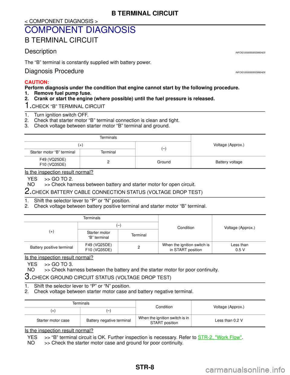
B TERMINAL CIRCUIT
COMPONENT DIAGNOSIS
B TERMINAL CIRCUIT
DescriptionINFOID:0000000003860425
The “B” terminal is constantly supplied with battery power.
Diagnosis ProcedureINFOID:0000000003860426
CAUTION:
Perform diagnosis under the condition that engine cannot start by the following procedure.
1. Remove fuel pump fuse.
2. Crank or start the engine (where possible) until the fuel pressure is released.
1.CHECK “B” TERMINAL CIRCUIT
1. Turn ignition switch OFF.
2. Check that starter motor “B” terminal connection is clean and tight.
3. Check voltage between starter motor “B” terminal and ground.
Is the inspection result normal?
YES >> GO TO 2.
NO >> Check harness between battery and starter motor for open circuit.
2.CHECK BATTERY CABLE CONNECTION STATUS (VOLTAGE DROP TEST)
1. Shift the selector lever to “P” or “N” position.
2. Check voltage between battery positive terminal and starter motor “B” terminal.
Is the inspection result normal?
YES >> GO TO 3.
NO >> Check harness between the battery and the starter motor for poor continuity.
3.CHECK GROUND CIRCUIT STATUS (VOLTAGE DROP TEST)
1. Shift the selector lever to “P” or “N” position.
2. Check voltage between starter motor case and battery negative terminal.
Is the inspection result normal?
YES >> “B” terminal circuit is OK. Further inspection is necessary. Refer to STR-2, "Work Flow".
NO >> Check the starter motor case and ground for poor continuity.
Te r m i n a l s
Voltage (Approx.) (+)
(–)
Starter motor “B” terminal Terminal
F49 (VQ25DE)
F10 (VQ35DE)2 Ground Battery voltage
Te r m i n a l s
Condition Voltage (Approx.)
(+)(–)
Starter motor
“B” terminalTerminal
Battery positive terminalF49 (VQ25DE)
F10 (VQ35DE)2 When the ignition switch is
in START positionLess than
0.5 V
Te r m i n a l s
Condition Voltage (Approx.)
(+) (–)
Starter motor case Battery negative terminalWhen the ignition switch is in
START positionLess than 0.2 V
Page 4456 of 5121
S TERMINAL CIRCUIT
STR-9
< COMPONENT DIAGNOSIS >
C
D
E
F
G
H
I
J
K
L
MA
STR
N
P O
S TERMINAL CIRCUIT
DescriptionINFOID:0000000003860427
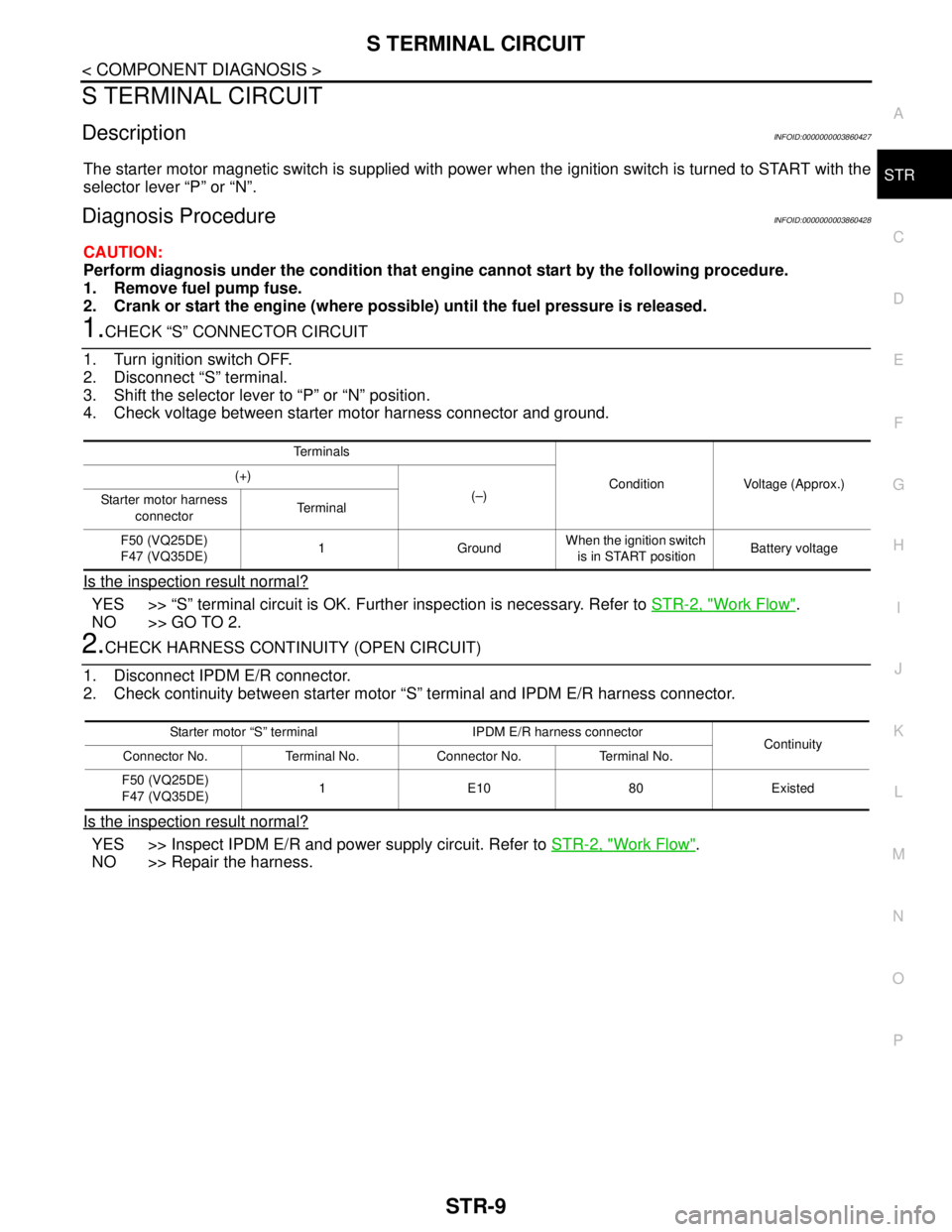
The starter motor magnetic switch is supplied with power when the ignition switch is turned to START with the
selector lever “P” or “N”.
Diagnosis ProcedureINFOID:0000000003860428
CAUTION:
Perform diagnosis under the condition that engine cannot start by the following procedure.
1. Remove fuel pump fuse.
2. Crank or start the engine (where possible) until the fuel pressure is released.
1.CHECK “S” CONNECTOR CIRCUIT
1. Turn ignition switch OFF.
2. Disconnect “S” terminal.
3. Shift the selector lever to “P” or “N” position.
4. Check voltage between starter motor harness connector and ground.
Is the inspection result normal?
YES >> “S” terminal circuit is OK. Further inspection is necessary. Refer to STR-2, "Work Flow".
NO >> GO TO 2.
2.CHECK HARNESS CONTINUITY (OPEN CIRCUIT)
1. Disconnect IPDM E/R connector.
2. Check continuity between starter motor “S” terminal and IPDM E/R harness connector.
Is the inspection result normal?
YES >> Inspect IPDM E/R and power supply circuit. Refer to STR-2, "Work Flow".
NO >> Repair the harness.
Te r m i n a l s
Condition Voltage (Approx.) (+)
(–)
Starter motor harness
connectorTe r m i n a l
F50 (VQ25DE)
F47 (VQ35DE)1 GroundWhen the ignition switch
is in START positionBattery voltage
Starter motor “S” terminal IPDM E/R harness connector
Continuity
Connector No. Terminal No. Connector No. Terminal No.
F50 (VQ25DE)
F47 (VQ35DE)1E1080Existed
Page 5091 of 5121
IPDM E/R (INTELLIGENT POWER DISTRIBUTION MODULE ENGINE ROOM)
WW-79
< ECU DIAGNOSIS >
C
D
E
F
G
H
I
J
K
MA
B
WW
N
O
P
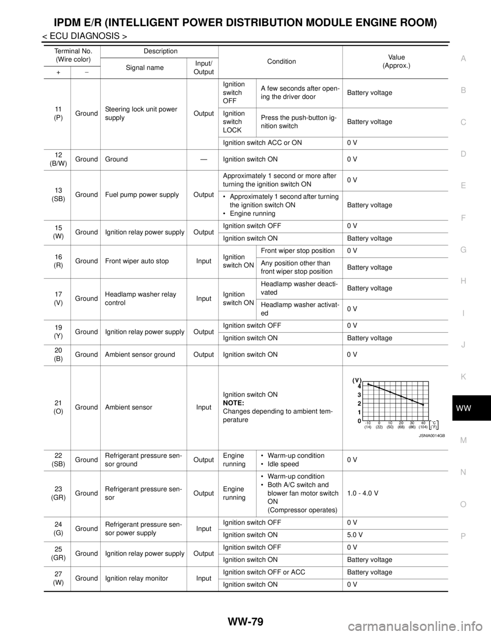
11
(P)GroundSteering lock unit power
supplyOutputIgnition
switch
OFFA few seconds after open-
ing the driver doorBattery voltage
Ignition
switch
LOCKPress the push-button ig-
nition switchBattery voltage
Ignition switch ACC or ON 0 V
12
(B/W)Ground Ground — Ignition switch ON 0 V
13
(SB)Ground Fuel pump power supply OutputApproximately 1 second or more after
turning the ignition switch ON0 V
Approximately 1 second after turning
the ignition switch ON
Engine runningBattery voltage
15
(W)Ground Ignition relay power supply OutputIgnition switch OFF 0 V
Ignition switch ON Battery voltage
16
(R)Ground Front wiper auto stop InputIgnition
switch ONFront wiper stop position 0 V
Any position other than
front wiper stop positionBattery voltage
17
(V)GroundHeadlamp washer relay
controlInputIgnition
switch ONHeadlamp washer deacti-
vatedBattery voltage
Headlamp washer activat-
ed0 V
19
(Y)Ground Ignition relay power supply OutputIgnition switch OFF 0 V
Ignition switch ON Battery voltage
20
(B)Ground Ambient sensor ground Output Ignition switch ON 0 V
21
(O)Ground Ambient sensor InputIgnition switch ON
NOTE:
Changes depending to ambient tem-
perature
22
(SB)GroundRefrigerant pressure sen-
sor groundOutputEngine
running Warm-up condition
Idle speed0 V
23
(GR)GroundRefrigerant pressure sen-
sorOutputEngine
running Warm-up condition
Both A/C switch and
blower fan motor switch
ON
(Compressor operates)1.0 - 4.0 V
24
(G)
GroundRefrigerant pressure sen-
sor power supplyInputIgnition switch OFF 0 V
Ignition switch ON 5.0 V
25
(GR)Ground Ignition relay power supply OutputIgnition switch OFF 0 V
Ignition switch ON Battery voltage
27
(W)Ground Ignition relay monitor InputIgnition switch OFF or ACC Battery voltage
Ignition switch ON 0 V Te r m i n a l N o .
(Wire color)Description
ConditionVa l u e
(Approx.)
Signal nameInput/
Output +−
JSNIA0014GB