2008 NISSAN TEANA radiator
[x] Cancel search: radiatorPage 3242 of 5121

SQUEAK AND RATTLE TROUBLE DIAGNOSES
MIR-9
< SYMPTOM DIAGNOSIS >
C
D
E
F
G
H
I
J
K
MA
B
MIR
N
O
P
Again, pressing on the components to stop the noise while duplicating the conditions can isolate most of these
incidents. Repairs usually consist of insulating with felt cloth tape.
SEATS
When isolating seat noise it is important to note the position the seat is in and the load placed on the seat
when the noise occurs. These conditions should be duplicated when verifying and isolating the cause of the
noise.
Cause of seat noise include:
1. Headrest rods and holder
2. A squeak between the seat pad cushion and frame
3. Rear seatback lock and bracket
These noises can be isolated by moving or pressing on the suspected components while duplicating the con-
ditions under which the noise occurs. Most of these incidents can be repaired by repositioning the component
or applying urethane tape to the contact area.
UNDERHOOD
Some interior noise may be caused by components under the hood or on the engine wall. The noise is then
transmitted into the passenger compartment.
Causes of transmitted underhood noise include:
1. Any component mounted to the engine wall
2. Components that pass through the engine wall
3. Engine wall mounts and connectors
4. Loose radiator mounting pins
5. Hood bumpers out of adjustment
6. Hood striker out of adjustment
These noises can be difficult to isolate since they cannot be reached from the interior of the vehicle. The best
method is to secure, move or insulate one component at a time and test drive the vehicle. Also, engine RPM
or load can be changed to isolate the noise. Repairs can usually be made by moving, adjusting, securing, or
insulating the component causing the noise.
Page 3805 of 5121

RF-74
< SYMPTOM DIAGNOSIS >
SQUEAK AND RATTLE TROUBLE DIAGNOSES
SEATS
When isolating seat noise it is important to note the position the seat is in and the load placed on the seat
when the noise occurs. These conditions should be duplicated when verifying and isolating the cause of the
noise.
Cause of seat noise include:
1. Headrest rods and holder
2. A squeak between the seat pad cushion and frame
3. Rear seatback lock and bracket
These noises can be isolated by moving or pressing on the suspected components while duplicating the con-
ditions under which the noise occurs. Most of these incidents can be repaired by repositioning the component
or applying urethane tape to the contact area.
UNDERHOOD
Some interior noise may be caused by components under the hood or on the engine wall. The noise is then
transmitted into the passenger compartment.
Causes of transmitted underhood noise include:
1. Any component mounted to the engine wall
2. Components that pass through the engine wall
3. Engine wall mounts and connectors
4. Loose radiator mounting pins
5. Hood bumpers out of adjustment
6. Hood striker out of adjustment
These noises can be difficult to isolate since they cannot be reached from the interior of the vehicle. The best
method is to secure, move or insulate one component at a time and test drive the vehicle. Also, engine RPM
or load can be changed to isolate the noise. Repairs can usually be made by moving, adjusting, securing, or
insulating the component causing the noise.
Page 3947 of 5121
![NISSAN TEANA 2008 Service Manual SQUEAK AND RATTLE TROUBLE DIAGNOSES
SE-83
< SYMPTOM DIAGNOSIS >[WITH VENTILATION SEAT]
C
D
E
F
G
H
I
K
L
MA
B
SE
N
O
P
SEATS
When isolating seat noise it is important to note the position the seat is NISSAN TEANA 2008 Service Manual SQUEAK AND RATTLE TROUBLE DIAGNOSES
SE-83
< SYMPTOM DIAGNOSIS >[WITH VENTILATION SEAT]
C
D
E
F
G
H
I
K
L
MA
B
SE
N
O
P
SEATS
When isolating seat noise it is important to note the position the seat is](/manual-img/5/57391/w960_57391-3946.png)
SQUEAK AND RATTLE TROUBLE DIAGNOSES
SE-83
< SYMPTOM DIAGNOSIS >[WITH VENTILATION SEAT]
C
D
E
F
G
H
I
K
L
MA
B
SE
N
O
P
SEATS
When isolating seat noise it is important to note the position the seat is in and the load placed on the seat
when the noise occurs. These conditions should be duplicated when verifying and isolating the cause of the
noise.
Cause of seat noise include:
1. Headrest rods and holder
2. A squeak between the seat pad cushion and frame
3. Rear seatback lock and bracket
These noises can be isolated by moving or pressing on the suspected components while duplicating the con-
ditions under which the noise occurs. Most of these incidents can be repaired by repositioning the component
or applying urethane tape to the contact area.
UNDERHOOD
Some interior noise may be caused by components under the hood or on the engine wall. The noise is then
transmitted into the passenger compartment.
Causes of transmitted underhood noise include:
1. Any component mounted to the engine wall
2. Components that pass through the engine wall
3. Engine wall mounts and connectors
4. Loose radiator mounting pins
5. Hood bumpers out of adjustment
6. Hood striker out of adjustment
These noises can be difficult to isolate since they cannot be reached from the interior of the vehicle. The best
method is to secure, move or insulate one component at a time and test drive the vehicle. Also, engine RPM
or load can be changed to isolate the noise. Repairs can usually be made by moving, adjusting, securing, or
insulating the component causing the noise.
Page 3988 of 5121
![NISSAN TEANA 2008 Service Manual SE-124
< SYMPTOM DIAGNOSIS >[WITHOUT VENTILATION SEAT]
SQUEAK AND RATTLE TROUBLE DIAGNOSES
Again, pressing on the components to stop the noise while duplicating the conditions can isolate most of thes NISSAN TEANA 2008 Service Manual SE-124
< SYMPTOM DIAGNOSIS >[WITHOUT VENTILATION SEAT]
SQUEAK AND RATTLE TROUBLE DIAGNOSES
Again, pressing on the components to stop the noise while duplicating the conditions can isolate most of thes](/manual-img/5/57391/w960_57391-3987.png)
SE-124
< SYMPTOM DIAGNOSIS >[WITHOUT VENTILATION SEAT]
SQUEAK AND RATTLE TROUBLE DIAGNOSES
Again, pressing on the components to stop the noise while duplicating the conditions can isolate most of these
incidents. Repairs usually consist of insulating with felt cloth tape.
SEATS
When isolating seat noise it is important to note the position the seat is in and the load placed on the seat
when the noise occurs. These conditions should be duplicated when verifying and isolating the cause of the
noise.
Cause of seat noise include:
1. Headrest rods and holder
2. A squeak between the seat pad cushion and frame
3. Rear seatback lock and bracket
These noises can be isolated by moving or pressing on the suspected components while duplicating the con-
ditions under which the noise occurs. Most of these incidents can be repaired by repositioning the component
or applying urethane tape to the contact area.
UNDERHOOD
Some interior noise may be caused by components under the hood or on the engine wall. The noise is then
transmitted into the passenger compartment.
Causes of transmitted underhood noise include:
1. Any component mounted to the engine wall
2. Components that pass through the engine wall
3. Engine wall mounts and connectors
4. Loose radiator mounting pins
5. Hood bumpers out of adjustment
6. Hood striker out of adjustment
These noises can be difficult to isolate since they cannot be reached from the interior of the vehicle. The best
method is to secure, move or insulate one component at a time and test drive the vehicle. Also, engine RPM
or load can be changed to isolate the noise. Repairs can usually be made by moving, adjusting, securing, or
insulating the component causing the noise.
Page 4232 of 5121

SR-18
< ON-VEHICLE REPAIR >
CRASH ZONE SENSOR
CRASH ZONE SENSOR
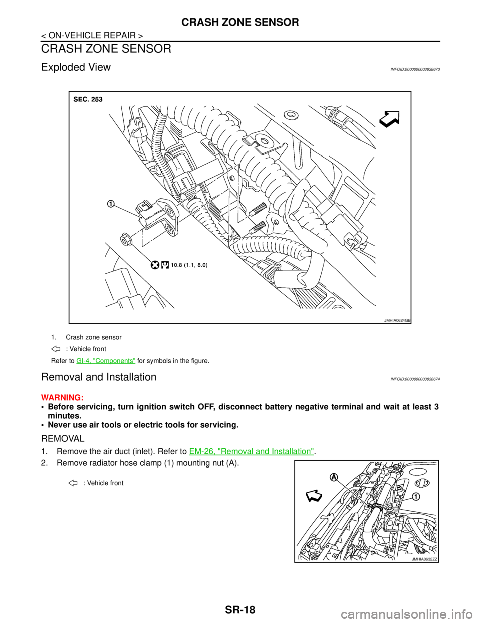
Exploded ViewINFOID:0000000003838673
Removal and InstallationINFOID:0000000003838674
WARNING:
Before servicing, turn ignition switch OFF, disconnect battery negative terminal and wait at least 3
minutes.
Never use air tools or electric tools for servicing.
REMOVAL
1. Remove the air duct (inlet). Refer to EM-26, "Removal and Installation".
2. Remove radiator hose clamp (1) mounting nut (A).
1. Crash zone sensor
: Vehicle front
Refer to GI-4, "
Components" for symbols in the figure.
JMHIA0624GB
: Vehicle front
JMHIA0632ZZ
Page 4267 of 5121

SRC-24
< COMPONENT DIAGNOSIS >
B1033, B1034 CRASH ZONE SEN
B1033, B1034 CRASH ZONE SEN
DescriptionINFOID:0000000003813948
Main “G” sensor generates signal voltage, when it detects deceleration beyond the specified level caused by
vehicle frontal collision.
OPERATION
When air bag diagnosis sensor unit defines both signal voltage of the “G” sensor and the safing algorithm to
be that of collision which exceeds specified level, the driving circuit switches on and feeds the electric ignitor of
both driver and passenger air bags and pre-tensioner seat belts.
STRUCTURE
Integrated type of the “G” sensor element for frontal collision with output terminals for signal voltage.
INSTALLATION
Crash zone sensor is installed on the radiator core support assembly with fixed nuts.
DTC LogicINFOID:0000000003813949
DTC CONFIRMATION PROCEDURE
1.CHECK SELF-DIAG RESULT
With CONSULT-III
1. Turn ignition switch ON.
2. Perform “AIR BAG” Self Diagnostic Result.
Without CONSULT-III
1. Turn ignition switch ON.
2. Check the air bag warning lamp status. Refer to SRC-10, "
Air Bag Warning Lamp Diagnosis".
NOTE:
SRS does not enter Diagnosis mode if no malfunction is detected in User mode.
Is malfunctioning part detected?
YES >> Refer to SRC-24, "Diagnosis Procedure".
NO >> INSPECTION END
Diagnosis ProcedureINFOID:0000000003813950
WARNING:
Before servicing, turn ignition switch OFF, disconnect battery negative terminal and wait at least 3
minutes. (To discharge backup capacitor.)
Never use unspecified tester or other measuring device.
1.CHECK HARNESS CONNECTOR
Check the harness connector.
Is the inspection result normal?
YES >> GO TO 2.
NO >> Replace harness connectors.
2.CHECK WIRING HARNESS
Check the wiring harness externals.
Is the inspection result normal?
YES >> GO TO 3.
NO >> Replace wiring harness.
DTC No. Trouble diagnosis name DTC detecting condition Possible cause
B1033
B1034CRASH ZONE SEN-
SOR
[UNIT FAIL]Crash zone sensor is out of order Disconnection of wiring harness
Malfunction in crash zone sensor
Malfunction in air bag diagnosis sen-
sor unit
Page 4269 of 5121

SRC-26
< COMPONENT DIAGNOSIS >
B1035, B1036 CRASH ZONE SEN
B1035, B1036 CRASH ZONE SEN
DescriptionINFOID:0000000003813951
Main “G” sensor generates signal voltage, when it detects deceleration beyond the specified level caused by
vehicle frontal collision.
OPERATION
When air bag diagnosis sensor unit defines both signal voltage of the “G” sensor and the safing algorithm to
be that of collision which exceeds a specified level, the driving circuit switches on and feeds the electric ignitor
of both driver and passenger air bags and pre-tensioner seat belts.
STRUCTURE
Integrated type of the “G” sensor element for frontal collision with output terminals for signal voltage.
INSTALLATION
Crash zone sensor is installed on the radiator core support assembly with fixed nuts.
DTC LogicINFOID:0000000003813952
DTC CONFIRMATION PROCEDURE
1.CHECK SELF-DIAG RESULT
With CONSULT-III
1. Turn ignition switch ON.
2. Perform “AIR BAG” Self Diagnostic Result.
Without CONSULT-III
1. Turn ignition switch ON.
2. Check the air bag warning lamp status. Refer to SRC-10, "
Air Bag Warning Lamp Diagnosis".
NOTE:
SRS does not enter Diagnosis mode if no malfunction is detected in User mode.
Is malfunctioning part detected?
YES >> Refer to SRC-26, "Diagnosis Procedure".
NO >> INSPECTION END
Diagnosis ProcedureINFOID:0000000003813953
WARNING:
Before servicing, turn ignition switch OFF, disconnect battery negative terminal and wait at least 3
minutes. (To discharge backup capacitor.)
Never use unspecified tester or other measuring device.
1.CHECK HARNESS CONNECTOR
Check the harness connector.
Is the inspection result normal?
YES >> GO TO 2.
NO >> Replace harness connectors.
2.CHECK WIRING HARNESS
Check the wiring harness externals.
Is the inspection result normal?
YES >> GO TO 3.
NO >> Replace wiring harness.
DTC No. Trouble diagnosis name DTC detecting condition Possible cause
B1035
B1036CRASH ZONE SEN-
SOR
[COMM FAIL]
[UNMATCH]Crash zone sensor is out of order Disconnection of wiring harness
Malfunction in crash zone sensor
Malfunction in air bag diagnosis sen-
sor unit
Page 4271 of 5121

SRC-28
< COMPONENT DIAGNOSIS >
B1037, B1039, B1041 CRASH ZONE SENS1
B1037, B1039, B1041 CRASH ZONE SENS1
DescriptionINFOID:0000000003941403
Main “G” sensor generates signal voltage, when it detects deceleration beyond the specified level caused by
vehicle frontal collision.
OPERATION
When air bag diagnosis sensor unit defines both signal voltage of the “G” sensor and the safing algorithm to
be that of collision which exceeds a specified level, the driving circuit switches on and feeds the electric ignitor
of both driver and passenger air bags and pre-tensioner seat belts.
STRUCTURE
Integrated type of the “G” sensor element for frontal collision with output terminals for signal voltage.
INSTALLATION
Crash zone sensor is installed on the radiator core support assembly with fixed nuts.
DTC LogicINFOID:0000000003941404
DTC CONFIRMATION PROCEDURE
1.CHECK SELF-DIAG RESULT
With CONSULT-III
1. Turn ignition switch ON.
2. Perform “AIR BAG” Self Diagnostic Result.
Without CONSULT-III
1. Turn ignition switch ON.
2. Check the air bag warning lamp status. Refer to SRC-10, "
Air Bag Warning Lamp Diagnosis".
NOTE:
SRS does not enter Diagnosis mode if no malfunction is detected in User mode.
Is malfunctioning part detected?
YES >> Refer to SRC-28, "Diagnosis Procedure".
NO >> INSPECTION END
Diagnosis ProcedureINFOID:0000000003941405
WARNING:
Before servicing, turn ignition switch OFF, disconnect battery negative terminal and wait at least 3
minutes. (To discharge backup capacitor.)
Never use unspecified tester or other measuring device.
1.CHECK HARNESS CONNECTOR
Check the harness connector.
Is the inspection result normal?
YES >> GO TO 2.
NO >> Replace harness connectors.
2.CHECK WIRING HARNESS
Check the wiring harness externals.
Is the inspection result normal?
YES >> GO TO 3.
NO >> Replace wiring harness.
DTC No. Trouble diagnosis name DTC detecting condition Possible cause
B1037
B1039
B1041CRASH ZONE
SENSOR1 Crash zone sensor is out of order Disconnection of wiring harness
Malfunction in crash zone sensor
Malfunction in air bag diagnosis sen-
sor unit