2008 NISSAN TEANA radiator
[x] Cancel search: radiatorPage 1713 of 5121
![NISSAN TEANA 2008 Service Manual EC-252
< COMPONENT DIAGNOSIS >[VQ25DE, VQ35DE]
P1217 ENGINE OVER TEMPERATURE
>> Repair or replace malfunctioning part.
4.CHECK RADIATOR CAP
Check radiator cap. Refer to CO-12, "
RADIATOR CAP : Inspect NISSAN TEANA 2008 Service Manual EC-252
< COMPONENT DIAGNOSIS >[VQ25DE, VQ35DE]
P1217 ENGINE OVER TEMPERATURE
>> Repair or replace malfunctioning part.
4.CHECK RADIATOR CAP
Check radiator cap. Refer to CO-12, "
RADIATOR CAP : Inspect](/manual-img/5/57391/w960_57391-1712.png)
EC-252
< COMPONENT DIAGNOSIS >[VQ25DE, VQ35DE]
P1217 ENGINE OVER TEMPERATURE
>> Repair or replace malfunctioning part.
4.CHECK RADIATOR CAP
Check radiator cap. Refer to CO-12, "
RADIATOR CAP : Inspection".
Is the inspection result normal?
YES >> GO TO 5.
NO >> Replace radiator cap.
5.CHECK THERMOSTAT
Check thermostat. Refer to CO-24, "
Inspection".
Is the inspection result normal?
YES >> GO TO 6.
NO >> Replace thermostat
6.CHECK ENGINE COOLANT TEMPERATURE SENSOR
Refer to EC-158, "
Component Inspection".
Is the inspection result normal?
YES >> GO TO 7.
NO >> Replace engine coolant temperature sensor.
7.CHECK MAIN 12 CAUSES
If the cause cannot be isolated, check the following.
*1: Turn the ignition switch ON.
*2: Engine running at 3,000 rpm for 10 minutes.
*3: Drive at 90 km/h (56 MPH) for 30 minutes and then let idle for 10 minutes.
*4: After 60 minutes of cool down time.
For more information, refer to CO-3, "
TroubleshootingChart". Engine Step Inspection item Equipment Standard Reference page
OFF 1 Blocked radiator
Blocked condenser
Blocked radiator grille
Blocked bumper Visual No blocking —
2 Coolant mixture Coolant testerMA-11, "
Fluids and Lubricants"
3 Coolant level Visual Coolant up to MAX level in
reservoir tank and radiator
filler neckCO-8, "Inspection"
4 Radiator cap Pressure testerCO-12, "RADIATOR CAP : Inspection"
ON*25 Coolant leaks Visual No leaksCO-8, "Inspection"
ON*26 Thermostat Touch the upper and
lower radiator hosesBoth hoses should be hotCO-24, "Inspection"
ON*17 Cooling fan CONSULT-III OperatingEC-324, "Component
Function Check"
OFF 8 Combustion gas leak Color checker chemical
tester 4 Gas analyzerNegative —
ON*
39 Coolant temperature
gauge Visual Gauge less than 3/4 when
driving—
Coolant overflow to res-
ervoir tank Visual No overflow during driving
and idlingCO-8, "
Inspection"
OFF*410 Coolant return from res-
ervoir tank to radiator Visual Should be initial level in
reservoir tankCO-8, "Inspection"
OFF 11 Cylinder head Straight gauge feeler
gauge0.1 mm (0.004 in) Maxi-
mum distortion (warping)EM-104, "Inspection"
12 Cylinder block and pis-
tons Visual No scuffing on cylinder
walls or pistonEM-119, "Inspection"
Page 1864 of 5121
![NISSAN TEANA 2008 Service Manual ENGINE CONTROL SYSTEM SYMPTOMS
EC-403
< SYMPTOM DIAGNOSIS >[VQ25DE, VQ35DE]
C
D
E
F
G
H
I
J
K
L
MA
EC
N
P O
1 - 6: The numbers refer to the order of inspection.Va l v e
mecha-
nismTiming chain
55555 NISSAN TEANA 2008 Service Manual ENGINE CONTROL SYSTEM SYMPTOMS
EC-403
< SYMPTOM DIAGNOSIS >[VQ25DE, VQ35DE]
C
D
E
F
G
H
I
J
K
L
MA
EC
N
P O
1 - 6: The numbers refer to the order of inspection.Va l v e
mecha-
nismTiming chain
55555](/manual-img/5/57391/w960_57391-1863.png)
ENGINE CONTROL SYSTEM SYMPTOMS
EC-403
< SYMPTOM DIAGNOSIS >[VQ25DE, VQ35DE]
C
D
E
F
G
H
I
J
K
L
MA
EC
N
P O
1 - 6: The numbers refer to the order of inspection.Va l v e
mecha-
nismTiming chain
55555 55 5EM-65
CamshaftEM-84
Intake valve timing controlEM-65
Intake valve
3EM-97
Exhaust valve
Exhaust Exhaust manifold/Tube/Muffler/
Gasket
55555 55 5EM-34
, EX-
4Three way catalyst
Lubrica-
tionOil pan/Oil strainer/Oil pump/Oil
filter/Oil gallery/Oil cooler
55555 55 5LU-7
, LU-
10, LU-11,
LU-13
Oil level (Low)/Filthy oilLU-7
Cooling
Radiator/Hose/Radiator filler cap
55555 55 45CO-12,
CO-12
Thermostat 5CO-23
Water pumpCO-18
Water galleryCO-2
Cooling fan
5CO-16
Coolant level (Low)/Contaminat-
ed coolantCO-8
NVIS (NISSAN Vehicle Immobilizer System —
NATS)11SEC-14
SYMPTOM
Reference
page
HARD/NO START/RESTART (EXCP. HA)
ENGINE STALL
HESITATION/SURGING/FLAT SPOT
SPARK KNOCK/DETONATION
LACK OF POWER/POOR ACCELERATION
HIGH IDLE/LOW IDLE
ROUGH IDLE/HUNTING
IDLING VIBRATION
SLOW/NO RETURN TO IDLE
OVERHEATS/WATER TEMPERATURE HIGH
EXCESSIVE FUEL CONSUMPTION
EXCESSIVE OIL CONSUMPTION
BATTERY DEAD (UNDER CHARGE)
Warranty symptom code AA AB AC AD AE AF AG AH AJ AK AL AM HA
Page 1905 of 5121

EM-30
< ON-VEHICLE REPAIR >
INTAKE MANIFOLD COLLECTOR
2. Remove air cleaner cases (upper and lower) with mass air flow sensor and air duct assembly. Refer to
EM-26, "
Exploded View".
3. Drain engine coolant, or when water hoses are disconnected, attach plug to prevent engine coolant leak-
age. Refer to CO-8, "
Draining".
CAUTION:
Perform this step when the engine is cold.
4. Remove front wiper arm and extension cowl top. Refer to WW-105, "
Exploded View" and EXT-20,
"Exploded View".
5. Disconnect water hoses from electric throttle control actuator.
When engine coolant is not drained from radiator, attach plug to water hoses to prevent engine coolant
leakage.
6. Remove electric throttle control actuator as follows:
a. Disconnect harness connector.
b. Loosen mounting bolts in reverse order as shown in the figure.
CAUTION:
Handle carefully to avoid any shock to electric throttle
control actuator.
Never disassemble.
7. Remove the following parts:
Vacuum hose
PCV hose
High pressure piping from intake manifold collector: Refer to ST-34, "
Exploded View".
Electronic controlled engine mount control solenoid valve
8. Disconnect EVAP hoses and harness connector from EVAP canister purge control solenoid valve.
9. Remove EVAP canister purge control solenoid valve and bracket assembly.
10. Remove VIAS control solenoid valve mounting bolts and vacuum gallery mounting bolts, and then move
vacuum gallery.
Add mating marks as necessary for easier installation.
11. Loosen mounting nuts and bolts in reverse order as shown in
the figure, and remove intake manifold collector and gasket.
CAUTION:
Cover engine openings to avoid entry of foreign materials.
NOTE:
Figure is shown as an example of VQ35DE.
INSTALLATION
Note the following, and install in the reverse order of removal.
Intake Manifold Collector
JPBIA1631ZZ
: Engine front
JPBIA1628ZZ
Page 1943 of 5121
EM-68
< REMOVAL AND INSTALLATION >
ENGINE ASSEMBLY
Place chocks at front and back of rear wheels.
For engines not equipped with engine slingers, attach proper slingers and bolts described in PARTS
CATALOG.
CAUTION:
Always be careful to work safely, avoid forceful or uninstructed operations.
Never start working until exhaust system and engine coolant are cool enough.
If items or work required are not covered by the engine section, refer to the applicable sections.
Always use the support point specified for lifting.
Use either 2-pole lift type or separate type lift as best you can. If board-on type is used for unavoid-
able reasons, support at the rear axle jacking point with transmission jack or similar tool before
starting work, in preparation for the backward shift of center of gravity.
For supporting points for lifting and jacking point at rear axle, refer to GI-30, "
Garage Jack and
Safety Stand and 2-Pole Lift".
REMOVAL
Outline
At first, remove the engine and the transaxle assembly with front suspension member downward. Then sepa-
rate the engine and the transaxle.
Preparation
1. Release fuel pressure. Refer to EC-411, "Inspection".
2. Drain engine coolant. Refer to CO-8, "
Draining".
CAUTION:
Perform this step when the engine is cold.
Never spill engine coolant on drive belt.
3. Remove the following parts:
Engine cover: Refer to EM-24, "
Exploded View".
Front road wheel and tires
Splash guards (RH and LH): Refer to EXT-22, "
FENDER PROTECTOR : Exploded View".
Air duct (inlet), air cleaner cases (upper and lower) with mass air flow sensor and air duct assembly:
Refer to EM-26, "
Exploded View".
Battery and battery tray: Refer to PG-109, "
Removal and Installation".
Drive belt: Refer to EM-12, "
Removal and Installation".
Reservoir tank of radiator. Refer to CO-13, "
Exploded View".
Front wiper arm: Refer to WW-105, "
Exploded View".
4. Disconnect engine room harness at the TCM, ECM and other sides.
CAUTION:
To keep clean harness connector and avoid damage and foreign materials, cover them completely
with plastic bags or something similar.
5. Remove battery bracket with ECM and TCM.
6. Remove extension cowl top. Refer to EXT-20, "
Exploded View".
Engine Room
1. Disconnect heater hoses. Refer to CO-25, "Exploded View".
Install plug to avoid leakage of engine coolant.
2. Remove EVAP hose. Refer to EM-28, "
Exploded View".
3. Disconnect fuel feed hose quick connector at fuel tube side. Refer to EM-44, "
Exploded View".
Install plug to avoid leakage of fuel.
4. Disconnect transaxle shift control cable at transaxle side. Refer to TM-319, "
Exploded View" (VQ25DE) or
TM-157, "
Exploded View" (VQ35DE).
5. Disconnect brake booster vacuum hose at engine side. Refer to EM-28, "
Exploded View".
6. Disconnect ground cable.
7. Disconnect A/C compressor piping at A/C compressor side. Refer to HA-36, "
Exploded View".
8. Disconnect suction hoses of power steering oil pump at reservoir tank side. Refer to ST-34, "
Exploded
View".
Install plug to avoid leakage of power steering fluid.
9. Disconnect CVT fluid cooler hoses from radiator. Refer to CO-13, "
Exploded View".
Page 2394 of 5121
SQUEAK AND RATTLE TROUBLE DIAGNOSES
EXT-5
< SYMPTOM DIAGNOSIS >
C
D
E
F
G
H
I
J
L
MA
B
EXT
N
O
P
Again, pressing on the components to stop the noise while duplicating the conditions can isolate most of these
incidents. Repairs usually consist of insulating with felt cloth tape.
SEATS
When isolating seat noise it is important to note the position the seat is in and the load placed on the seat
when the noise occurs. These conditions must duplicated when verifying and isolating the cause of the noise.
Cause of seat noise include:
1. Headrest rods and holder
2. A squeak between the seat pad cushion and frame
3. Rear seatback lock and bracket
These noises can be isolated by moving or pressing on the suspected components while duplicating the con-
ditions under which the noise occurs. Most of these incidents can be repaired by repositioning the component
or applying urethane tape to the contact area.
UNDERHOOD
Some interior noise may be caused by components under the hood or on the engine wall. The noise is then
transmitted into the passenger compartment.
Causes of transmitted underhood noise include:
1. Any component mounted to the engine wall
2. Components that pass through the engine wall
3. Engine wall mounts and connectors
4. Loose radiator mounting pins
5. Hood bumpers out of adjustment
6. Hood striker out of adjustment
These noises can be difficult to isolate since they cannot be reached from the interior of the vehicle. The best
method is to secure, move or insulate one component at a time and test drive the vehicle. Also, engine RPM
or load can be changed to isolate the noise. Repairs can usually be made by moving, adjusting, securing, or
insulating the component causing the noise.
Page 2519 of 5121
GI-26
< PRECAUTION >
PRECAUTIONS
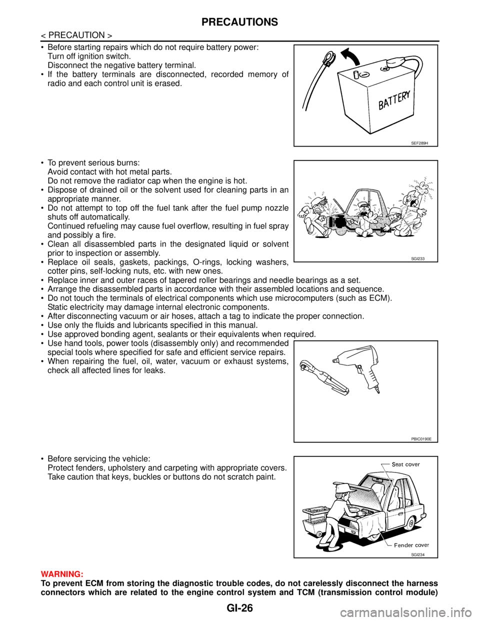
Before starting repairs which do not require battery power:
Turn off ignition switch.
Disconnect the negative battery terminal.
If the battery terminals are disconnected, recorded memory of
radio and each control unit is erased.
To prevent serious burns:
Avoid contact with hot metal parts.
Do not remove the radiator cap when the engine is hot.
Dispose of drained oil or the solvent used for cleaning parts in an
appropriate manner.
Do not attempt to top off the fuel tank after the fuel pump nozzle
shuts off automatically.
Continued refueling may cause fuel overflow, resulting in fuel spray
and possibly a fire.
Clean all disassembled parts in the designated liquid or solvent
prior to inspection or assembly.
Replace oil seals, gaskets, packings, O-rings, locking washers,
cotter pins, self-locking nuts, etc. with new ones.
Replace inner and outer races of tapered roller bearings and needle bearings as a set.
Arrange the disassembled parts in accordance with their assembled locations and sequence.
Do not touch the terminals of electrical components which use microcomputers (such as ECM).
Static electricity may damage internal electronic components.
After disconnecting vacuum or air hoses, attach a tag to indicate the proper connection.
Use only the fluids and lubricants specified in this manual.
Use approved bonding agent, sealants or their equivalents when required.
Use hand tools, power tools (disassembly only) and recommended
special tools where specified for safe and efficient service repairs.
When repairing the fuel, oil, water, vacuum or exhaust systems,
check all affected lines for leaks.
Before servicing the vehicle:
Protect fenders, upholstery and carpeting with appropriate covers.
Take caution that keys, buckles or buttons do not scratch paint.
WARNING:
To prevent ECM from storing the diagnostic trouble codes, do not carelessly disconnect the harness
connectors which are related to the engine control system and TCM (transmission control module)
SEF289H
SGI233
PBIC0190E
SGI234
Page 2548 of 5121
SQUEAK AND RATTLE TROUBLE DIAGNOSES
GW-5
< SYMPTOM DIAGNOSIS >
C
D
E
F
G
H
I
J
L
MA
B
GW
N
O
P
Again, pressing on the components to stop the noise while duplicating the conditions can isolate most of these
incidents. Repairs usually consist of insulating with felt cloth tape.
SEATS
When isolating seat noise it is important to note the position the seat is in and the load placed on the seat
when the noise occurs. These conditions should be duplicated when verifying and isolating the cause of the
noise.
Cause of seat noise include:
1. Headrest rods and holder
2. A squeak between the seat pad cushion and frame
3. Rear seatback lock and bracket
These noises can be isolated by moving or pressing on the suspected components while duplicating the con-
ditions under which the noise occurs. Most of these incidents can be repaired by repositioning the component
or applying urethane tape to the contact area.
UNDERHOOD
Some interior noise may be caused by components under the hood or on the engine wall. The noise is then
transmitted into the passenger compartment.
Causes of transmitted underhood noise include:
1. Any component mounted to the engine wall
2. Components that pass through the engine wall
3. Engine wall mounts and connectors
4. Loose radiator mounting pins
5. Hood bumpers out of adjustment
6. Hood striker out of adjustment
These noises can be difficult to isolate since they cannot be reached from the interior of the vehicle. The best
method is to secure, move or insulate one component at a time and test drive the vehicle. Also, engine RPM
or load can be changed to isolate the noise. Repairs can usually be made by moving, adjusting, securing, or
insulating the component causing the noise.
Page 2605 of 5121
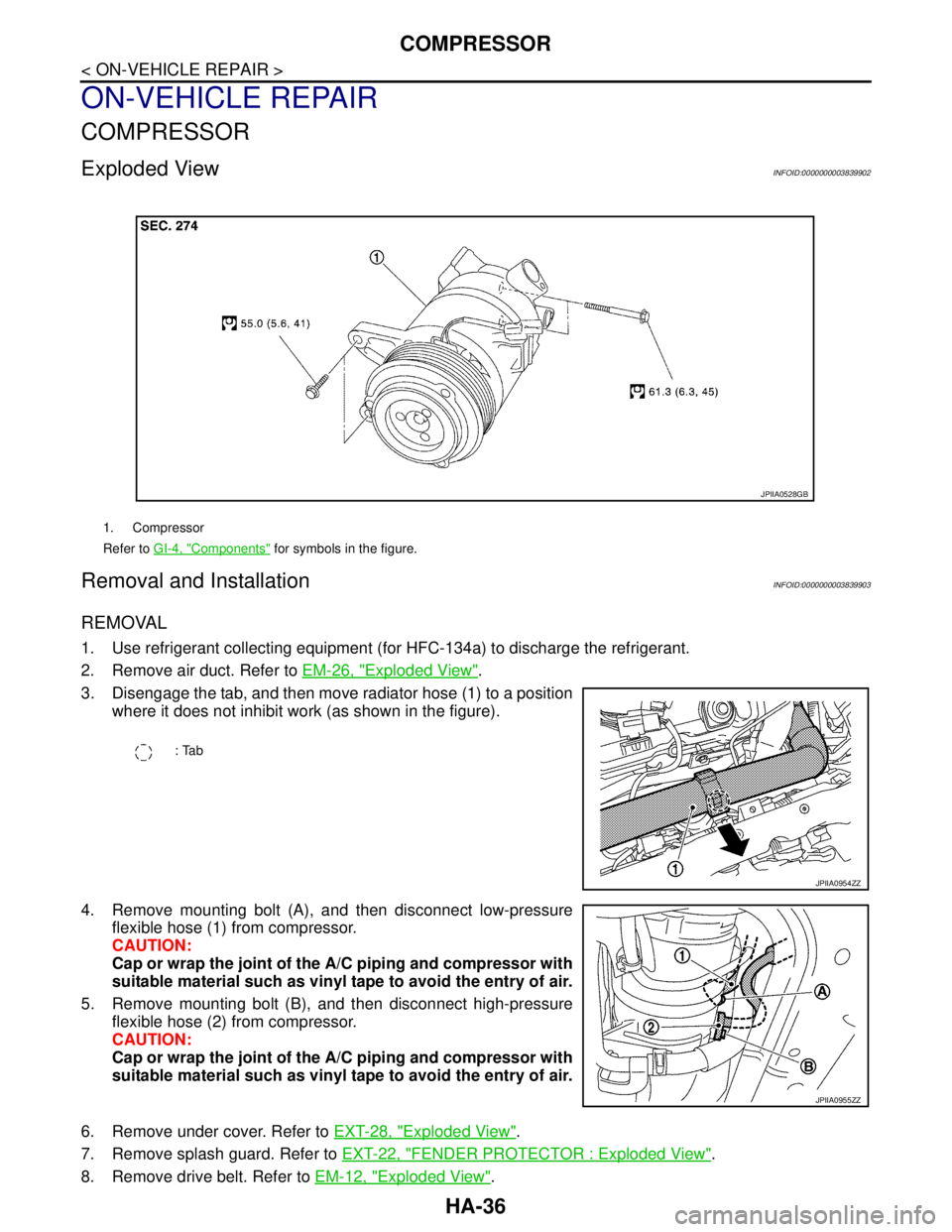
HA-36
< ON-VEHICLE REPAIR >
COMPRESSOR
ON-VEHICLE REPAIR
COMPRESSOR
Exploded ViewINFOID:0000000003839902
Removal and InstallationINFOID:0000000003839903
REMOVAL
1. Use refrigerant collecting equipment (for HFC-134a) to discharge the refrigerant.
2. Remove air duct. Refer to EM-26, "
Exploded View".
3. Disengage the tab, and then move radiator hose (1) to a position
where it does not inhibit work (as shown in the figure).
4. Remove mounting bolt (A), and then disconnect low-pressure
flexible hose (1) from compressor.
CAUTION:
Cap or wrap the joint of the A/C piping and compressor with
suitable material such as vinyl tape to avoid the entry of air.
5. Remove mounting bolt (B), and then disconnect high-pressure
flexible hose (2) from compressor.
CAUTION:
Cap or wrap the joint of the A/C piping and compressor with
suitable material such as vinyl tape to avoid the entry of air.
6. Remove under cover. Refer to EXT-28, "
Exploded View".
7. Remove splash guard. Refer to EXT-22, "
FENDER PROTECTOR : Exploded View".
8. Remove drive belt. Refer to EM-12, "
Exploded View".
1. Compressor
Refer to GI-4, "
Components" for symbols in the figure.
JPIIA0528GB
: Tab
JPIIA0954ZZ
JPIIA0955ZZ