2008 NISSAN TEANA radiator
[x] Cancel search: radiatorPage 1146 of 5121
WATER INLET AND THERMOSTAT ASSEMBLY
CO-23
< ON-VEHICLE REPAIR >
C
D
E
F
G
H
I
J
K
L
MA
CO
N
P O
WATER INLET AND THERMOSTAT ASSEMBLY
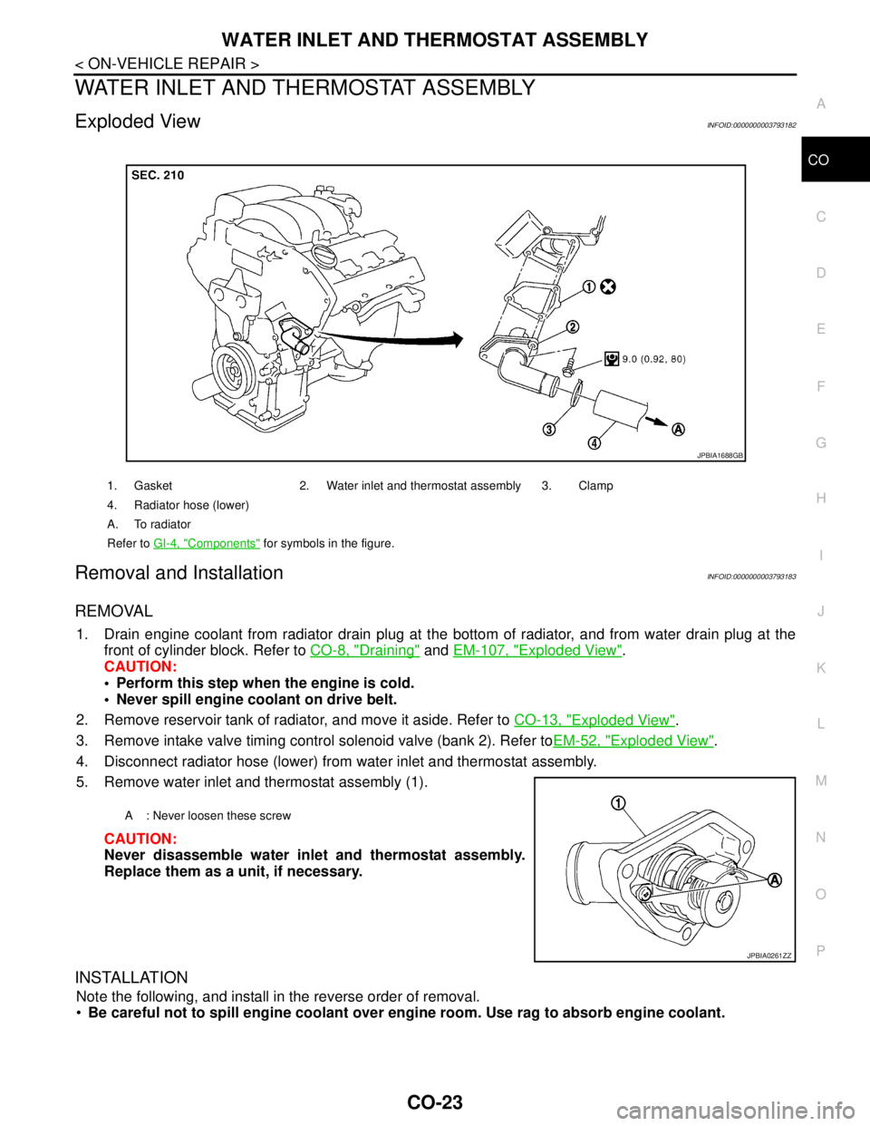
Exploded ViewINFOID:0000000003793182
Removal and InstallationINFOID:0000000003793183
REMOVAL
1. Drain engine coolant from radiator drain plug at the bottom of radiator, and from water drain plug at the
front of cylinder block. Refer to CO-8, "
Draining" and EM-107, "Exploded View".
CAUTION:
Perform this step when the engine is cold.
Never spill engine coolant on drive belt.
2. Remove reservoir tank of radiator, and move it aside. Refer to CO-13, "
Exploded View".
3. Remove intake valve timing control solenoid valve (bank 2). Refer toEM-52, "
Exploded View".
4. Disconnect radiator hose (lower) from water inlet and thermostat assembly.
5. Remove water inlet and thermostat assembly (1).
CAUTION:
Never disassemble water inlet and thermostat assembly.
Replace them as a unit, if necessary.
INSTALLATION
Note the following, and install in the reverse order of removal.
Be careful not to spill engine coolant over engine room. Use rag to absorb engine coolant.
1. Gasket 2. Water inlet and thermostat assembly 3. Clamp
4. Radiator hose (lower)
A. To radiator
Refer to GI-4, "
Components" for symbols in the figure.
JPBIA1688GB
A : Never loosen these screw
JPBIA0261ZZ
Page 1147 of 5121
CO-24
< ON-VEHICLE REPAIR >
WATER INLET AND THERMOSTAT ASSEMBLY
Inspection
INFOID:0000000003793184
INSPECTION AFTER REMOVAL
1. Check valve seating condition at ordinary room temperatures. It should seat tightly.
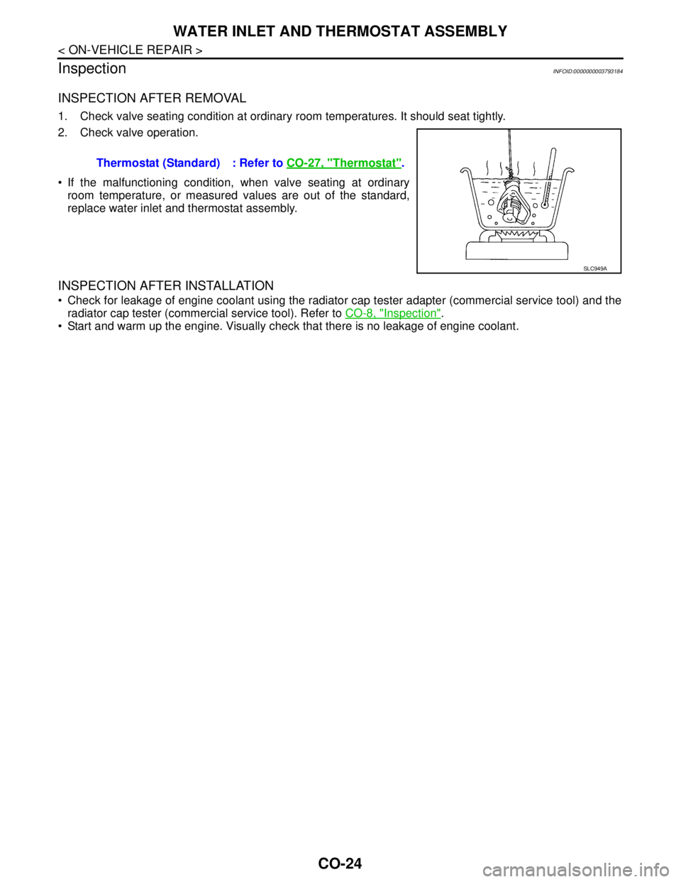
2. Check valve operation.
If the malfunctioning condition, when valve seating at ordinary
room temperature, or measured values are out of the standard,
replace water inlet and thermostat assembly.
INSPECTION AFTER INSTALLATION
Check for leakage of engine coolant using the radiator cap tester adapter (commercial service tool) and the
radiator cap tester (commercial service tool). Refer to CO-8, "
Inspection".
Start and warm up the engine. Visually check that there is no leakage of engine coolant. Thermostat (Standard) : Refer to CO-27, "
Thermostat".
SLC949A
Page 1148 of 5121
WATER OUTLET AND WATER PIPING
CO-25
< ON-VEHICLE REPAIR >
C
D
E
F
G
H
I
J
K
L
MA
CO
N
P O
WATER OUTLET AND WATER PIPING
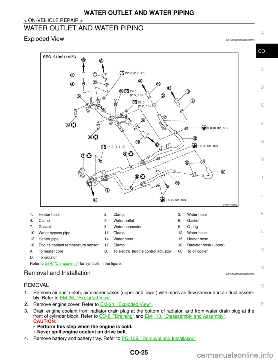
Exploded ViewINFOID:0000000003793185
Removal and InstallationINFOID:0000000003793186
REMOVAL
1. Remove air duct (inlet), air cleaner cases (upper and lower) with mass air flow sensor and air duct assem-
bly. Refer to EM-26, "
Exploded View".
2. Remove engine cover. Refer to EM-24, "
Exploded View".
3. Drain engine coolant from radiator drain plug at the bottom of radiator, and from water drain plug at the
front of cylinder block. Refer to CO-8, "
Draining" and EM-110, "Disassembly and Assembly".
CAUTION:
Perform this step when the engine is cold.
Never spill engine coolant on drive belt.
4. Remove battery and battery tray. Refer to PG-109, "
Removal and Installation".
1. Heater hose 2. Clamp 3. Water hose
4. Clamp 5. Water outlet 6. Gasket
7. Gasket 8. Water connector 9. O-ring
10. Water bypass pipe 11. Clamp 12. Water hose
13. Heater pipe 14. Water hose 15. Heater hose
16. Engine coolant temperature sensor 17. Clamp 18. Radiator hose (upper)
A. To heater core B. To electric throttle control actuator C. To oil cooler
D. To radiator
Refer to GI-4, "
Components" for symbols in the figure.
JPBIA1691GB
Page 1149 of 5121
CO-26
< ON-VEHICLE REPAIR >
WATER OUTLET AND WATER PIPING
5. Remove CVT fluid charging pipe and CVT fluid level gauge. Refer to TM-332, "Exploded View" (VQ25DE)
or TM-168, "
Exploded View" (VQ35DE).
6. Move CVT control cable aside. Refer to TM-319, "
Exploded View" (VQ25DE) or TM-157, "Exploded View"
(VQ35DE).
7. Remove vacuum pipe (front) mounting bolt from water outlet. Refer to EM-67, "
Exploded View".
8. Remove radiator hose (upper) from water outlet.
9. Remove water hoses and heater hoses.
10. Disconnect harness connectors, and move harness to aside.
11. Remove engine coolant temperature sensor as necessary.
CAUTION:
Be careful not to damage engine coolant temperature sensor.
12. Remove water outlet, heater pipe, water bypass pipe and water connector.
INSTALLATION
Note the following, and install in the reverse order of removal.
Securely insert each hose, and install clamp at a position where it does not interfere with the pipe bulge.
When inserting water bypass pipe and heater pipe into water connector, apply neutral detergent to O-ring.
InspectionINFOID:0000000003793187
INSPECTION AFTER INSTALLATION
Check for leakage of engine coolant using the radiator cap tester adapter (commercial service tool) and the
radiator cap tester (commercial service tool). Refer to CO-8, "
Inspection".
Start and warm up the engine. Visually check that there is no leakage of engine coolant.
Page 1150 of 5121
SERVICE DATA AND SPECIFICATIONS (SDS)
CO-27
< SERVICE DATA AND SPECIFICATIONS (SDS)
C
D
E
F
G
H
I
J
K
L
MA
CO
N
P O
SERVICE DATA AND SPECIFICATIONS (SDS)
SERVICE DATA AND SPECIFICATIONS (SDS)
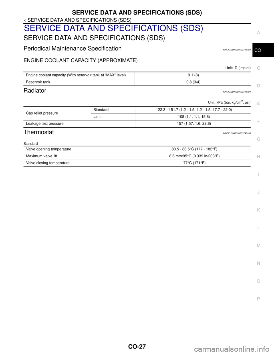
Periodical Maintenance SpecificationINFOID:0000000003793188
ENGINE COOLANT CAPACITY (APPROXIMATE)
Unit: (lmp qt)
RadiatorINFOID:0000000003793189
Unit: kPa (bar, kg/cm2, psi)
ThermostatINFOID:0000000003793190
Standard
Engine coolant capacity (With reservoir tank at “MAX” level) 9.1 (8)
Reservoir tank0.8 (3/4)
Cap relief pressureStandard 122.3 - 151.7 (1.2 - 1.5, 1.2 - 1.5, 17.7 - 22.0)
Limit 108 (1.1, 1.1, 15.6)
Leakage test pressure 157 (1.57, 1.6, 22.8)
Valve opening temperature 80.5 - 83.5°C (177 - 182°F)
Maximum valve lift 8.6 mm/95°C (0.339 in/203°F)
Valve closing temperature 77°C (171°F)
Page 1221 of 5121
DLK-5
C
D
E
F
G
H
I
J
L
MA
B
DLK
N
O
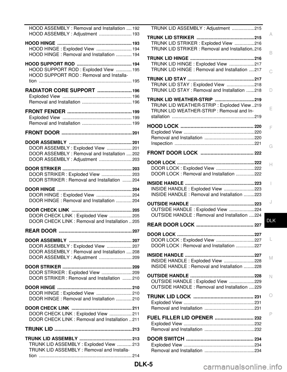
P HOOD ASSEMBLY : Removal and Installation .....
192
HOOD ASSEMBLY : Adjustment ..........................193
HOOD HINGE ..........................................................193
HOOD HINGE : Exploded View ............................194
HOOD HINGE : Removal and Installation .............194
HOOD SUPPORT ROD ...........................................194
HOOD SUPPORT ROD : Exploded View .............195
HOOD SUPPORT ROD : Removal and Installa-
tion ........................................................................
195
RADIATOR CORE SUPPORT .........................196
Exploded View ......................................................196
Removal and Installation .......................................196
FRONT FENDER ..............................................199
Exploded View ......................................................199
Removal and Installation .......................................199
FRONT DOOR ..................................................201
DOOR ASSEMBLY .................................................201
DOOR ASSEMBLY : Exploded View ....................201
DOOR ASSEMBLY : Removal and Installation .....202
DOOR ASSEMBLY : Adjustment ..........................203
DOOR STRIKER ......................................................203
DOOR STRIKER : Exploded View ........................203
DOOR STRIKER : Removal and Installation ........204
DOOR HINGE ..........................................................204
DOOR HINGE : Exploded View ............................204
DOOR HINGE : Removal and Installation .............204
DOOR CHECK LINK ...............................................205
DOOR CHECK LINK : Exploded View ..................205
DOOR CHECK LINK : Removal and Installation ..205
REAR DOOR ....................................................207
DOOR ASSEMBLY .................................................207
DOOR ASSEMBLY : Exploded View ....................207
DOOR ASSEMBLY : Removal and Installation .....208
DOOR ASSEMBLY : Adjustment ..........................209
DOOR STRIKER ......................................................209
DOOR STRIKER : Exploded View ........................209
DOOR STRIKER : Removal and Installation ........210
DOOR HINGE ..........................................................210
DOOR HINGE : Exploded View ............................210
DOOR HINGE : Removal and Installation .............210
DOOR CHECK LINK ...............................................211
DOOR CHECK LINK : Exploded View ..................211
DOOR CHECK LINK : Removal and Installation ..211
TRUNK LID .......................................................213
TRUNK LID ASSEMBLY .........................................213
TRUNK LID ASSEMBLY : Exploded View ............213
TRUNK LID ASSEMBLY : Removal and Installa-
tion ........................................................................
214
TRUNK LID ASSEMBLY : Adjustment ..................215
TRUNK LID STRIKER .............................................215
TRUNK LID STRIKER : Exploded View ................216
TRUNK LID STRIKER : Removal and Installation ..216
TRUNK LID HINGE ..................................................216
TRUNK LID HINGE : Exploded View ....................217
TRUNK LID HINGE : Removal and Installation .....217
TRUNK LID STAY ....................................................217
TRUNK LID STAY : Exploded View ......................218
TRUNK LID STAY : Removal and Installation .......218
TRUNK LID WEATHER-STRIP ...............................219
TRUNK LID WEATHER-STRIP : Exploded View ..219
TRUNK LID WEATHER-STRIP : Removal and In-
stallation ................................................................
219
HOOD LOCK ...................................................220
Exploded View .......................................................220
Removal and Installation .......................................220
Inspection ..............................................................221
FRONT DOOR LOCK .....................................222
DOOR LOCK ............................................................222
DOOR LOCK : Exploded View ..............................222
DOOR LOCK : Removal and Installation ...............222
INSIDE HANDLE ......................................................223
INSIDE HANDLE : Exploded View ........................223
INSIDE HANDLE : Removal and Installation .........223
OUTSIDE HANDLE ..................................................223
OUTSIDE HANDLE : Exploded View ....................224
OUTSIDE HANDLE : Removal and Installation .....224
REAR DOOR LOCK ........................................227
DOOR LOCK ............................................................227
DOOR LOCK : Exploded View ..............................227
DOOR LOCK : Removal and Installation ...............227
INSIDE HANDLE ......................................................227
INSIDE HANDLE : Exploded View ........................228
INSIDE HANDLE : Removal and Installation .........228
OUTSIDE HANDLE ..................................................228
OUTSIDE HANDLE : Exploded View ....................229
OUTSIDE HANDLE : Removal and Installation .....229
TRUNK LID LOCK ..........................................231
Exploded View .......................................................231
Removal and Installation .......................................231
FUEL FILLER LID OPENER ...........................232
Exploded View .......................................................232
Removal and Installation .......................................232
DOOR SWITCH ...............................................234
Exploded View .......................................................234
Removal and Installation .......................................234
Page 1401 of 5121
![NISSAN TEANA 2008 Service Manual SQUEAK AND RATTLE TROUBLE DIAGNOSES
DLK-185
< SYMPTOM DIAGNOSIS >[WITH INTELLIGENT KEY SYSTEM]
C
D
E
F
G
H
I
J
L
MA
B
DLK
N
O
P
SEATS
When isolating seat noise it is important to note the position the NISSAN TEANA 2008 Service Manual SQUEAK AND RATTLE TROUBLE DIAGNOSES
DLK-185
< SYMPTOM DIAGNOSIS >[WITH INTELLIGENT KEY SYSTEM]
C
D
E
F
G
H
I
J
L
MA
B
DLK
N
O
P
SEATS
When isolating seat noise it is important to note the position the](/manual-img/5/57391/w960_57391-1400.png)
SQUEAK AND RATTLE TROUBLE DIAGNOSES
DLK-185
< SYMPTOM DIAGNOSIS >[WITH INTELLIGENT KEY SYSTEM]
C
D
E
F
G
H
I
J
L
MA
B
DLK
N
O
P
SEATS
When isolating seat noise it is important to note the position the seat is in and the load placed on the seat
when the noise occurs. These conditions should be duplicated when verifying and isolating the cause of the
noise.
Cause of seat noise include:
1. Headrest rods and holder
2. A squeak between the seat pad cushion and frame
3. Rear seatback lock and bracket
These noises can be isolated by moving or pressing on the suspected components while duplicating the con-
ditions under which the noise occurs. Most of these incidents can be repaired by repositioning the component
or applying urethane tape to the contact area.
UNDERHOOD
Some interior noise may be caused by components under the hood or on the engine wall. The noise is then
transmitted into the passenger compartment.
Causes of transmitted underhood noise include:
1. Any component mounted to the engine wall
2. Components that pass through the engine wall
3. Engine wall mounts and connectors
4. Loose radiator mounting pins
5. Hood bumpers out of adjustment
6. Hood striker out of adjustment
These noises can be difficult to isolate since they cannot be reached from the interior of the vehicle. The best
method is to secure, move or insulate one component at a time and test drive the vehicle. Also, engine RPM
or load can be changed to isolate the noise. Repairs can usually be made by moving, adjusting, securing, or
insulating the component causing the noise.
Page 1407 of 5121
![NISSAN TEANA 2008 Service Manual HOOD
DLK-191
< ON-VEHICLE REPAIR >[WITH INTELLIGENT KEY SYSTEM]
C
D
E
F
G
H
I
J
L
MA
B
DLK
N
O
P
ON-VEHICLE REPAIR
HOOD
HOOD ASSEMBLY
HOOD ASSEMBLY : Exploded ViewINFOID:0000000003813383
REMOVAL
ADJUS NISSAN TEANA 2008 Service Manual HOOD
DLK-191
< ON-VEHICLE REPAIR >[WITH INTELLIGENT KEY SYSTEM]
C
D
E
F
G
H
I
J
L
MA
B
DLK
N
O
P
ON-VEHICLE REPAIR
HOOD
HOOD ASSEMBLY
HOOD ASSEMBLY : Exploded ViewINFOID:0000000003813383
REMOVAL
ADJUS](/manual-img/5/57391/w960_57391-1406.png)
HOOD
DLK-191
< ON-VEHICLE REPAIR >[WITH INTELLIGENT KEY SYSTEM]
C
D
E
F
G
H
I
J
L
MA
B
DLK
N
O
P
ON-VEHICLE REPAIR
HOOD
HOOD ASSEMBLY
HOOD ASSEMBLY : Exploded ViewINFOID:0000000003813383
REMOVAL
ADJUSTMENT
1. Hood insulator 2. Hood hinge (RH/LH) 3. Hood seal (front) (RH/LH)
4. Radiator core seal 5. Grommet 6. Hood support rod
7. Clamp 8. Hood assembly 9. Hood bumper rubber (lower) (RH/
LH)
10. Hood bumper rubber (side) (RH/LH)
Refer to GI-4, "
Components" for symbols in the figure.
JMKIA2380ZZ