2008 NISSAN TEANA radiator
[x] Cancel search: radiatorPage 2607 of 5121

HA-38
< ON-VEHICLE REPAIR >
LOW-PRESSURE FLEXIBLE HOSE
LOW-PRESSURE FLEXIBLE HOSE
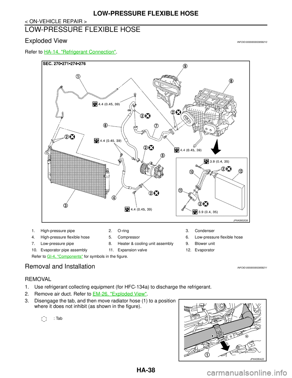
Exploded ViewINFOID:0000000003858210
Refer to HA-14, "Refrigerant Connection".
Removal and InstallationINFOID:0000000003858211
REMOVAL
1. Use refrigerant collecting equipment (for HFC-134a) to discharge the refrigerant.
2. Remove air duct. Refer to EM-26, "
Exploded View".
3. Disengage the tab, and then move radiator hose (1) to a position
where it does not inhibit (as shown in the figure).
1. High-pressure pipe 2. O-ring 3. Condenser
4. High-pressure flexible hose 5. Compressor 6. Low-pressure flexible hose
7. Low-pressure pipe 8. Heater & cooling unit assembly 9. Blower unit
10. Evaporator pipe assembly 11. Expansion valve 12. Evaporator
Refer to GI-4, "
Components" for symbols in the figure.
JPIIA0952GB
: Tab
JPIIA0954ZZ
Page 2609 of 5121

HA-40
< ON-VEHICLE REPAIR >
HIGH-PRESSURE FLEXIBLE HOSE
HIGH-PRESSURE FLEXIBLE HOSE
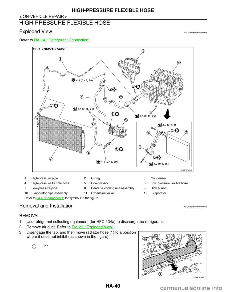
Exploded ViewINFOID:0000000003839908
Refer to HA-14, "Refrigerant Connection".
Removal and InstallationINFOID:0000000003839909
REMOVAL
1. Use refrigerant collecting equipment (for HFC-134a) to discharge the refrigerant.
2. Remove air duct. Refer to EM-26, "
Exploded View".
3. Disengage the tab, and then move radiator hose (1) to a position
where it does not inhibit (as shown in the figure).
1. High-pressure pipe 2. O-ring 3. Condenser
4. High-pressure flexible hose 5. Compressor 6. Low-pressure flexible hose
7. Low-pressure pipe 8. Heater & cooling unit assembly 9. Blower unit
10. Evaporator pipe assembly 11. Expansion valve 12. Evaporator
Refer to GI-4, "
Components" for symbols in the figure.
JPIIA0952GB
: Tab
JPIIA0954ZZ
Page 2719 of 5121
![NISSAN TEANA 2008 Service Manual INSUFFICIENT HEATING
HAC-91
< SYMPTOM DIAGNOSIS >[WITHOUT 7 INCH DISPLAY]
C
D
E
F
G
H
J
K
L
MA
B
HAC
N
O
P
INSUFFICIENT HEATING
DescriptionINFOID:0000000003846388
Symptom
Insufficient heating
No w NISSAN TEANA 2008 Service Manual INSUFFICIENT HEATING
HAC-91
< SYMPTOM DIAGNOSIS >[WITHOUT 7 INCH DISPLAY]
C
D
E
F
G
H
J
K
L
MA
B
HAC
N
O
P
INSUFFICIENT HEATING
DescriptionINFOID:0000000003846388
Symptom
Insufficient heating
No w](/manual-img/5/57391/w960_57391-2718.png)
INSUFFICIENT HEATING
HAC-91
< SYMPTOM DIAGNOSIS >[WITHOUT 7 INCH DISPLAY]
C
D
E
F
G
H
J
K
L
MA
B
HAC
N
O
P
INSUFFICIENT HEATING
DescriptionINFOID:0000000003846388
Symptom
Insufficient heating
No warm air comes out. (Air flow volume is normal.)
Inspection procedureINFOID:0000000003846389
1.CHECK COOLING SYSTEM
1. Check engine coolant level and check for leakage. Refer to CO-8, "
Inspection".
2. Check radiator cap. Refer to CO-12, "
RADIATOR CAP : Inspection".
3. Check water flow sounds of engine coolant. Refer to CO-9, "
Refilling".
Is the inspection result normal?
YES >> GO TO 2.
NO >> Refill the engine coolant and repair or replace the parts according to the inspection results.
2.CHECK OPERATION
1. Press temperature control switch (driver side) and raise temperature setting to 32°C (90°F) after warming
up the engine.
2. Check that warm air blows from the outlets.
Is the inspection result normal?
YES >> END.
NO >> GO TO 3.
3.CHECK SETTING OF TEMPERATURE SETTING TRIMMER
Using CONSULT-III, check the setting of “TEMP SET CORRECT” on “WORK SUPPORT” of HVAC. Refer to
HAC-10, "
Temperature Setting Trimmer".
1. Check that the temperature setting trimmer is set to “− direction”.
NOTE:
The control temperature can be set by the temperature setting trimmer.
2. Set temperature control switch to “0”.
Are the malfunction solved?
YES >> Perform the setting separately if necessary. END.
NO >> GO TO 4.
4.CHECK WITH SELF-DIAGNOSIS FUNCTION OF CONSULT-III
1. Using CONSULT-III, perform “SELF-DIAGNOSIS RESULTS” of HVAC.
2. Check if any DTC is displayed in the trouble diagnosis results.
NOTE:
If DTC is displayed along with DTC U1000 or U1010, first diagnose the DTC U1000 or U1010. Refer to
HAC-42, "
DTC Logic" or HAC-43, "DTC Logic".
Is any DTC displayed?
YES >> Perform the diagnosis that is applicable to the sensor and the door motor. Refer to HAC-85, "DTC
Index".
NO >> GO TO 5.
5.CHECK WITH ACTIVE TEST OF CONSULT-III
1. Using CONSULT-III, perform “HVAC TEST” in “ACTIVE TEST” of HVAC to check each output device.
Refer to HAC-38, "
CONSULT-III Function".
NOTE:
Perform the ACTIVE TEST after starting the engine because the compressor is operated.
2. Refer to the table and check the outlet, inlet, air flow temperature, blower motor control signal, magnet
clutch operation, and air mix ratio. Visually check each operating condition, by listening for noise, touching
air outlets with a hand, etc.
Page 2859 of 5121
![NISSAN TEANA 2008 Service Manual INSUFFICIENT HEATING
HAC-231
< SYMPTOM DIAGNOSIS >[WITH 7 INCH DISPLAY]
C
D
E
F
G
H
J
K
L
MA
B
HAC
N
O
P
INSUFFICIENT HEATING
DescriptionINFOID:0000000003884803
Symptom
Insufficient heating
No war NISSAN TEANA 2008 Service Manual INSUFFICIENT HEATING
HAC-231
< SYMPTOM DIAGNOSIS >[WITH 7 INCH DISPLAY]
C
D
E
F
G
H
J
K
L
MA
B
HAC
N
O
P
INSUFFICIENT HEATING
DescriptionINFOID:0000000003884803
Symptom
Insufficient heating
No war](/manual-img/5/57391/w960_57391-2858.png)
INSUFFICIENT HEATING
HAC-231
< SYMPTOM DIAGNOSIS >[WITH 7 INCH DISPLAY]
C
D
E
F
G
H
J
K
L
MA
B
HAC
N
O
P
INSUFFICIENT HEATING
DescriptionINFOID:0000000003884803
Symptom
Insufficient heating
No warm air comes out. (Air flow volume is normal.)
Inspection procedureINFOID:0000000003884804
1.CHECK COOLING SYSTEM
1. Check engine coolant level and check for leakage. Refer to CO-8, "
Inspection".
2. Check radiator cap. Refer to CO-12, "
RADIATOR CAP : Inspection".
3. Check water flow sounds of engine coolant. Refer to CO-9, "
Refilling".
Is the inspection result normal?
YES >> GO TO 2.
NO >> Refill the engine coolant and repair or replace the parts according to the inspection results.
2.CHECK OPERATION
1. Press temperature control dial (driver side) and raise temperature setting to 32°C (90°F) after warming up
the engine.
2. Check that warm air blows from the outlets.
Is the inspection result normal?
YES >> END.
NO >> GO TO 3.
3.CHECK SETTING OF TEMPERATURE SETTING TRIMMER
Using CONSULT-III, check the setting of “TEMP SET CORRECT” on “WORK SUPPORT” of HVAC. Refer to
HAC-110, "
WITHOUT INTELLIGENT AIR CONDITIONER SYSTEM : Temperature Setting Trimmer" (WITH-
OUT INTELLIGENT AIR CONDITIONER SYSTEM) or HAC-114, "
WITH INTELLIGENT AIR CONDITIONER
SYSTEM : Temperature Setting Trimmer" (WITH INTELLIGENT AIR CONDITIONER SYSTEM).
1. Check that the temperature setting trimmer is set to “− direction”.
NOTE:
The control temperature can be set by the temperature setting trimmer.
2. Set temperature control dial to “0”.
Are the malfunction solved?
YES >> Perform the setting separately if necessary. END.
NO >> GO TO 4.
4.CHECK WITH SELF-DIAGNOSIS FUNCTION OF CONSULT-III
1. Using CONSULT-III, perform “SELF-DIAGNOSIS RESULTS” of HVAC.
2. Check if any DTC is displayed in the trouble diagnosis results.
NOTE:
If DTC is displayed along with DTC U1000 or U1010, first diagnose the DTC U1000 or U1010. Refer to
HAC-164, "
DTC Logic" or HAC-165, "DTC Logic".
Is any DTC displayed?
YES >> Perform the diagnosis that is applicable to the sensor and the door motor. Refer to HAC-212,
"WITHOUT INTELLIGENT AIR CONDITIONER SYSTEM : DTC Index" (WITHOUT INTELLI-
GENT AIR CONDITIONER SYSTEM) or HAC-224, "
WITH INTELLIGENT AIR CONDITIONER
SYSTEM : DTC Index" (WITH INTELLIGENT AIR CONDITIONER SYSTEM).
NO >> GO TO 5.
5.CHECK WITH ACTIVE TEST OF CONSULT-III
1. Using CONSULT-III, perform “HVAC TEST” in “ACTIVE TEST” of HVAC to check each output device.
Refer to HAC-156, "
WITHOUT INTELLIGENT AIR CONDITIONER SYSTEM : CONSULT-III Function"
(WITHOUT INTELLIGENT AIR CONDITIONER SYSTEM) or HAC-159, "WITH INTELLIGENT AIR CON-
DITIONER SYSTEM : CONSULT-III Function" (WITH INTELLIGENT AIR CONDITIONER SYSTEM).
NOTE:
Page 3001 of 5121

INT-24
< SYMPTOM DIAGNOSIS >
SQUEAK AND RATTLE TROUBLE DIAGNOSES
SEATS
When isolating seat noise it is important to note the position the seat is in and the load placed on the seat
when the noise occurs. These conditions should be duplicated when verifying and isolating the cause of the
noise.
Cause of seat noise include:
1. Headrest rods and holder
2. A squeak between the seat pad cushion and frame
3. Rear seatback lock and bracket
These noises can be isolated by moving or pressing on the suspected components while duplicating the con-
ditions under which the noise occurs. Most of these incidents can be repaired by repositioning the component
or applying urethane tape to the contact area.
UNDERHOOD
Some interior noise may be caused by components under the hood or on the engine wall. The noise is then
transmitted into the passenger compartment.
Causes of transmitted underhood noise include:
1. Any component mounted to the engine wall
2. Components that pass through the engine wall
3. Engine wall mounts and connectors
4. Loose radiator mounting pins
5. Hood bumpers out of adjustment
6. Hood striker out of adjustment
These noises can be difficult to isolate since they cannot be reached from the interior of the vehicle. The best
method is to secure, move or insulate one component at a time and test drive the vehicle. Also, engine RPM
or load can be changed to isolate the noise. Repairs can usually be made by moving, adjusting, securing, or
insulating the component causing the noise.
Page 3045 of 5121

SQUEAK AND RATTLE TROUBLE DIAGNOSES
IP-5
< SYMPTOM DIAGNOSIS >
C
D
E
F
G
H
I
K
L
MA
B
IP
N
O
P
Again, pressing on the components to stop the noise while duplicating the conditions can isolate most of these
incidents. Repairs usually consist of insulating with felt cloth tape.
SEATS
When isolating seat noise it is important to note the position the seat is in and the load placed on the seat
when the noise occurs. These conditions should be duplicated when verifying and isolating the cause of the
noise.
Cause of seat noise include:
1. Headrest rods and holder
2. A squeak between the seat pad cushion and frame
3. Rear seatback lock and bracket
These noises can be isolated by moving or pressing on the suspected components while duplicating the con-
ditions under which the noise occurs. Most of these incidents can be repaired by repositioning the component
or applying urethane tape to the contact area.
UNDERHOOD
Some interior noise may be caused by components under the hood or on the engine wall. The noise is then
transmitted into the passenger compartment.
Causes of transmitted underhood noise include:
1. Any component mounted to the engine wall
2. Components that pass through the engine wall
3. Engine wall mounts and connectors
4. Loose radiator mounting pins
5. Hood bumpers out of adjustment
6. Hood striker out of adjustment
These noises can be difficult to isolate since they cannot be reached from the interior of the vehicle. The best
method is to secure, move or insulate one component at a time and test drive the vehicle. Also, engine RPM
or load can be changed to isolate the noise. Repairs can usually be made by moving, adjusting, securing, or
insulating the component causing the noise.
Page 3183 of 5121

OIL COOLER
LU-11
< ON-VEHICLE REPAIR >
C
D
E
F
G
H
I
J
K
L
MA
LU
N
P O
ON-VEHICLE REPAIR
OIL COOLER
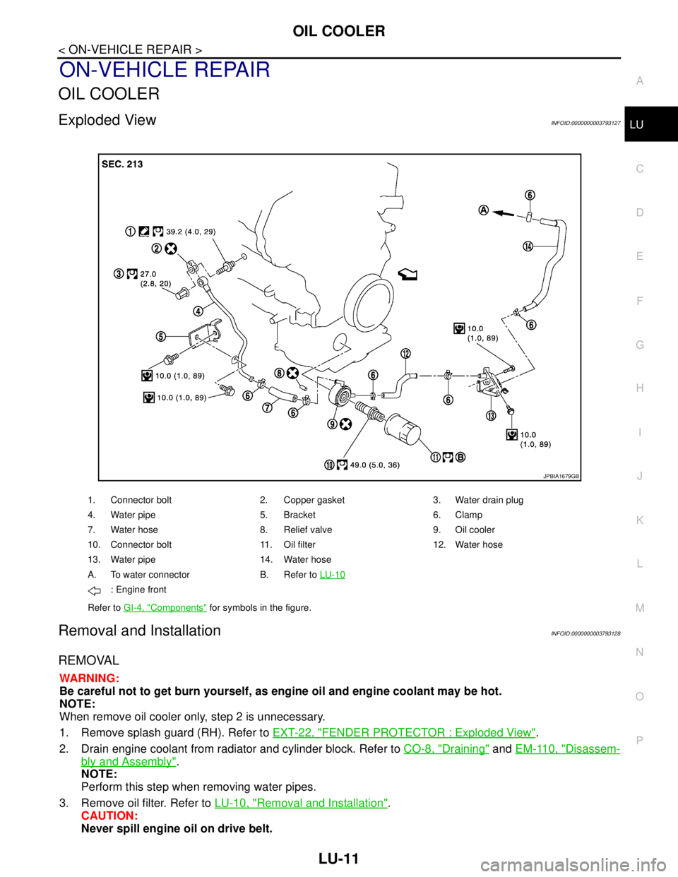
Exploded ViewINFOID:0000000003793127
Removal and InstallationINFOID:0000000003793128
REMOVAL
WARNING:
Be careful not to get burn yourself, as engine oil and engine coolant may be hot.
NOTE:
When remove oil cooler only, step 2 is unnecessary.
1. Remove splash guard (RH). Refer to EXT-22, "
FENDER PROTECTOR : Exploded View".
2. Drain engine coolant from radiator and cylinder block. Refer to CO-8, "
Draining" and EM-110, "Disassem-
bly and Assembly".
NOTE:
Perform this step when removing water pipes.
3. Remove oil filter. Refer to LU-10, "
Removal and Installation".
CAUTION:
Never spill engine oil on drive belt.
1. Connector bolt 2. Copper gasket 3. Water drain plug
4. Water pipe 5. Bracket 6. Clamp
7. Water hose 8. Relief valve 9. Oil cooler
10. Connector bolt 11. Oil filter 12. Water hose
13. Water pipe 14. Water hose
A. To water connector B. Refer to LU-10
: Engine front
Refer to GI-4, "
Components" for symbols in the figure.
JPBIA1679GB
Page 3189 of 5121

MA-1
MAINTENANCE
C
DE
F
G H
I
J
K L
M B
MA
SECTION MA
N
O A
CONTENTS
MAINTENANCE
PREPARATION .............
...............................3
PREPARATION .............................................. .....3
Special Service Tool ........................................... ......3
Commercial Service Tool ..........................................3
Pre-Delivery Inspection Item .....................................3
ON-VEHICLE MAINTENANCE .....................5
GENERAL MAINTENANCE ........................... .....5
General Maintenance .......................................... ......5
PERIODIC MAINTENANCE ................................6
Periodic Maintenance .......................................... ......6
RECOMMENDED FLUIDS AND LUBRI-
CANTS ................................................................
11
Fluids and Lubricants .......................................... ....11
SAE Viscosity Number ............................................11
Engine Coolant Mixture Ratio .................................12
ENGINE MAINTENANCE ...................................13
DRIVE BELT .......................................................... ....13
DRIVE BELT : Exploded View ................................13
DRIVE BELT : Checking .........................................13
DRIVE BELT : Tension Adjustment ........................13
ENGINE COOLANT ............................................... ....13
ENGINE COOLANT : Inspection .............................13
ENGINE COOLANT : Draining ................................14
ENGINE COOLANT : Refilling ................................14
ENGINE COOLANT : Flushing ...............................16
RADIATOR CAP .................................................... ....16
RADIATOR CAP : Inspection ..................................17
RADIATOR ............................................................ ....17
RADIATOR : Inspection ..........................................17
FUEL LINES .......................................................... ....17
FUEL LINES : Inspection ........................................18
AIR CLEANER FILTER ......................................... ....18
AIR CLEANER FILTER : Removal and Installation
....
18
ENGINE OIL ........................................................... ....18
ENGINE OIL : Draining ............................................18
ENGINE OIL : Refilling ............................................19
OIL FILTER ............................................................ ....19
OIL FILTER : Removal and Installation ...................19
OIL FILTER : Inspection ..........................................20
SPARK PLUG ........................................................ ....20
SPARK PLUG : Removal and Installation ...............20
SPARK PLUG : Inspection ......................................21
POSITIVE CRANKCASE VENTILATION SYSTEM ....21
POSITIVE CRANKCASE VENTILATION SYS-
TEM : Inspection ......................................................
21
EVAP VAPOR LINES ............................................ ....22
EVAP VAPOR LINES : Inspection ...........................22
CHASSIS MAINTENANCE ...............................23
HEADLAMP AIMING ADJUSTMENT (XENON
TYPE) .......... ................................. ..............................
23
HEADLAMP AIMING ADJUSTMENT (XENON
TYPE) : Description ............................................. ....
23
HEADLAMP AIMING ADJUSTMENT (XENON
TYPE) : Aiming Adjustment Procedure (Low
Beam) ......................................................................
24
HEADLAMP AIMING ADJUSTMENT (XENON
TYPE) : Aiming Adjustment Procedure (High
Beam) ......................................................................
25
HEADLAMP AIMING ADJUSTMENT (HALOGEN
TYPE) ........................................... ..............................
27
HEADLAMP AIMING ADJUSTMENT (HALOGEN
TYPE) : Description ............................................. ....
27
HEADLAMP AIMING ADJUSTMENT (HALOGEN
TYPE) : Aiming Adjustment Procedure (Low
Beam) ......................................................................
29