Page 3872 of 5121
![NISSAN TEANA 2008 Service Manual SE-8
< FUNCTION DIAGNOSIS >[WITH VENTILATION SEAT]
HEATED SEAT
HEATED SEAT
System DiagramINFOID:0000000003820817
System DescriptionINFOID:0000000003820814
The heated seat system is controlled by the](/manual-img/5/57391/w960_57391-3871.png "NISSAN TEANA 2008 Service Manual SE-8
< FUNCTION DIAGNOSIS >[WITH VENTILATION SEAT]
HEATED SEAT
HEATED SEAT
System DiagramINFOID:0000000003820817
System DescriptionINFOID:0000000003820814
The heated seat system is controlled by the")
SE-8
< FUNCTION DIAGNOSIS >[WITH VENTILATION SEAT]
HEATED SEAT
HEATED SEAT
System DiagramINFOID:0000000003820817
System DescriptionINFOID:0000000003820814
The heated seat system is controlled by the ventilation seat control unit.
The heated seat system consists of the heated seat switch, the heater unit and the ventilation seat control
unit.
The function of the heated seat system is to warm the seat surface.
The heated seat system has a LO and HI mode that can be switched back and forth. The LO mode warms
the seat surface slowly and the HI mode warms it quickly.
The indicator on the heated seat switch indicates the operating status of each mode.
NOTE:
The memory function is adopted for the front seat. When the ignition switch turns ON again after turning
OFF, while the heated seat is being operated, the heated seat system restarts at the same warmness as
the previous operation.
For the rear seat, when the ignition switch turns ON again after turning OFF, while the heated seat is being
operated, the heated seat system does not restart and stays in the OFF position.
While the heated seat system is being operated, the ventilation seat system becomes invalid.
LO MODE OPERATION
When the LO button of the heated seat switch is pressed, while the ignition switch is ON, the ventilation seat
control unit supplies the seat heater with the LO mode power supply and simultaneously illuminates the LO
mode indicator in the heated seat switch.
The seat heater warms the seat cushion and seatback to a low temperature by the LO mode power supply.
When the LO button is pressed again, while the heated seat switch is in the LO mode position, the indicator
and the heated seat switch turn OFF.
HI MODE OPERATION
When the HI button of the heated seat switch is pressed, while the ignition switch is ON, the Ventilation and
Heated seat control unit supplies the seat heater with the HI mode power supply and simultaneously illumi-
nates the HI mode indicator in the heated seat switch.
The seat heater warms the seat cushion and seatback to a high temperature by the HI mode power supply.
When the HI button is pressed again, while the heated seat switch is in the HI mode position, the indicator
and the heated seat switch turn OFF.
FA I L - S A F E
The fail-safe function is adopted for the ventilation seat control unit. Refer to SE-59, "FRONT SEAT : Fail-
safe".
JMJIA1932GB
Page 3874 of 5121
![NISSAN TEANA 2008 Service Manual SE-10
< FUNCTION DIAGNOSIS >[WITH VENTILATION SEAT]
VENTILATION SEAT SYSTEM
VENTILATION SEAT SYSTEM
System DiagramINFOID:0000000003820819
System DescriptionINFOID:0000000003809309
The ventilation se](/manual-img/5/57391/w960_57391-3873.png "NISSAN TEANA 2008 Service Manual SE-10
< FUNCTION DIAGNOSIS >[WITH VENTILATION SEAT]
VENTILATION SEAT SYSTEM
VENTILATION SEAT SYSTEM
System DiagramINFOID:0000000003820819
System DescriptionINFOID:0000000003809309
The ventilation se")
SE-10
< FUNCTION DIAGNOSIS >[WITH VENTILATION SEAT]
VENTILATION SEAT SYSTEM
VENTILATION SEAT SYSTEM
System DiagramINFOID:0000000003820819
System DescriptionINFOID:0000000003809309
The ventilation seat system consists of the ventilation seat switch, the ventilation motor and the ventilation
seat control unit.
The ventilation seat system blows air from the seat surface and reduces heat and humidity.
The ventilation seat system has a LO and HI mode that can be switched back and forth. The LO mode blows
air moderately from the seat surface and the HI mode blows air strongly.
The indicator on the heated seat switch indicates the operation status of each mode.
NOTE:
The memory function is adopted for the front seat. When the ignition switch turns ON again after turning
OFF, while the ventilation seat is being operated, the ventilation seat system restarts at the same air flow
setting as the previous operation.
For the rear seat, when the ignition switch turns ON again after turning OFF, while the ventilation seat is
being operated, the heated ventilation seat system does not restart and stays in the OFF position.
While the ventilation seat system is being operated, the heated seat system becomes invalid.
LO MODE OPERATION
When the LO button of the ventilation seat switch is pressed while the ignition switch is ON, the ventilation
seat control unit outputs the power supply to the ventilation motor and simultaneously illuminates the LO
mode indicator in the ventilation seat switch.
The ventilation motor is controlled in LO mode by the LO mode ventilation motor speed control signal from
the ventilation control unit. The ventilation motor sends moderate air flow to the seat cushion and seat back.
When the LO button is pressed again while the ventilation seat switch is in the LO mode position, the indica-
tor and the ventilation seat switch turn OFF.
HI MODE OPERATION
When the HI button of the ventilation seat switch is pressed while the ignition switch is ON, the ventilation
seat control unit outputs the power supply to the ventilation motor and simultaneously illuminates the HI
mode indicator in the ventilation seat switch.
The ventilation motor is controlled in HI mode by the HI mode ventilation motor speed control signal from the
ventilation control unit. The ventilation motor sends strong air flow to the seat cushion and seat back.
When the HI button is pressed again while the ventilation seat switch is in the HI mode position, the indicator
and the ventilation seat switch turn OFF.
FA I L - S A F E
The fail-safe function is adopted for the ventilation seat control unit. Refer to SE-59, "FRONT SEAT : Fail-
safe".
JMJIA1933GB
Page 4237 of 5121
DIAGNOSIS SENSOR UNIT
SR-23
< ON-VEHICLE REPAIR >
C
D
E
F
G
I
J
K
L
MA
B
SR
N
O
P
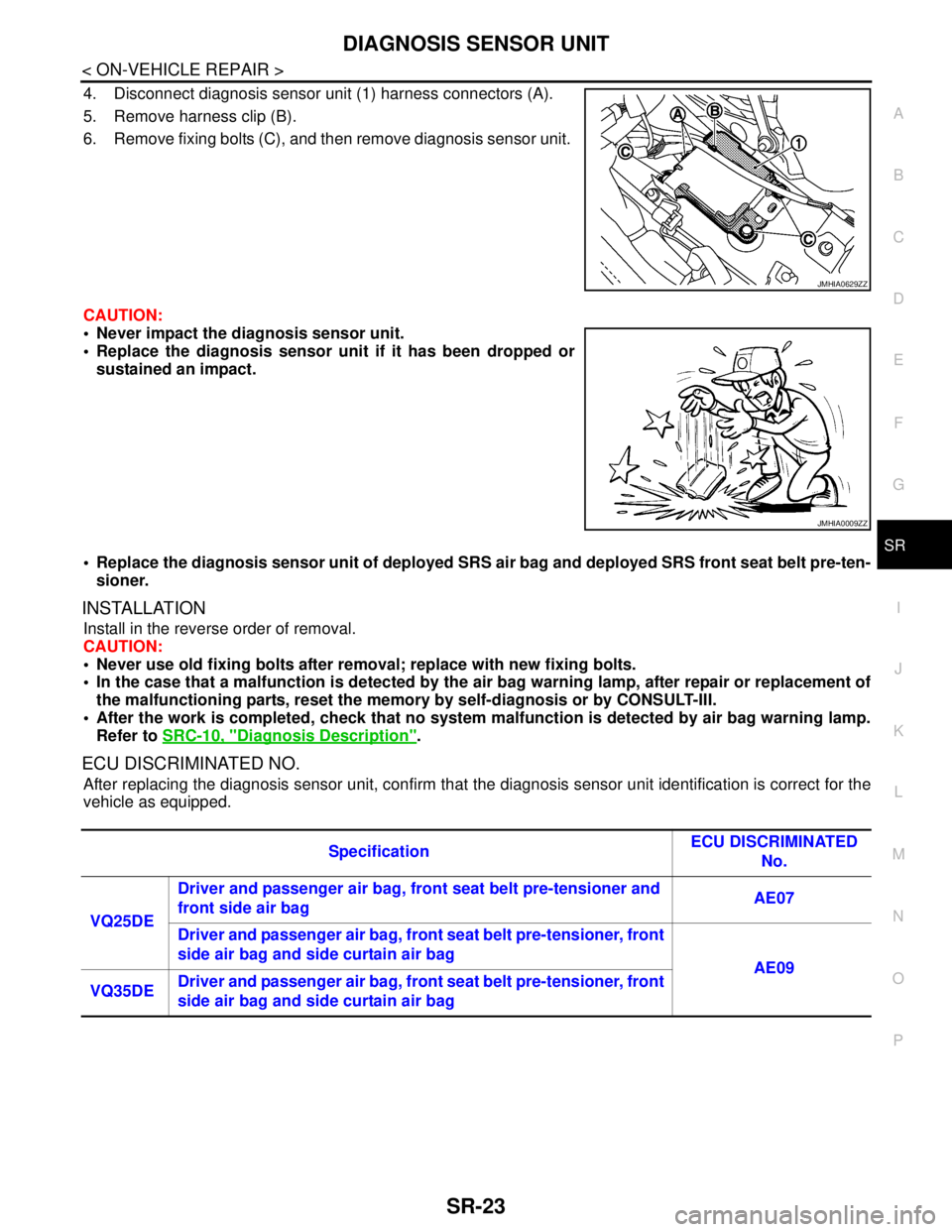
4. Disconnect diagnosis sensor unit (1) harness connectors (A).
5. Remove harness clip (B).
6. Remove fixing bolts (C), and then remove diagnosis sensor unit.
CAUTION:
Never impact the diagnosis sensor unit.
Replace the diagnosis sensor unit if it has been dropped or
sustained an impact.
Replace the diagnosis sensor unit of deployed SRS air bag and deployed SRS front seat belt pre-ten-
sioner.
INSTALLATION
Install in the reverse order of removal.
CAUTION:
Never use old fixing bolts after removal; replace with new fixing bolts.
In the case that a malfunction is detected by the air bag warning lamp, after repair or replacement of
the malfunctioning parts, reset the memory by self-diagnosis or by CONSULT-III.
After the work is completed, check that no system malfunction is detected by air bag warning lamp.
Refer to SRC-10, "
Diagnosis Description".
ECU DISCRIMINATED NO.
After replacing the diagnosis sensor unit, confirm that the diagnosis sensor unit identification is correct for the
vehicle as equipped.
JMHIA0629ZZ
JMHIA0009ZZ
SpecificationECU DISCRIMINATED
No.
VQ25DE Driver and passenger air bag, front seat belt pre-tensioner and
front side air bag AE07
Driver and passenger air bag, front seat belt pre-tensioner, front
side air bag and side curtain air bag
AE09
VQ35DEDriver and passenger air bag, front seat belt pre-tensioner, front
side air bag and side curtain air bag