Page 3007 of 5121
INT-30
< ON-VEHICLE REPAIR >
FRONT DOOR FINISHER
ON-VEHICLE REPAIR
FRONT DOOR FINISHER
DRIVER SIDE
DRIVER SIDE : Exploded ViewINFOID:0000000003819216
DRIVER SIDE : Removal and InstallationINFOID:0000000003819217
CAUTION:
Wrap the tip of flat-bladed screwdriver with a cloth before remove.
REMOVAL
1. Front door panel 2. Front door inside handle 3. Power window switch finisher
4. Front door finisher 5. Inside handle escutcheon 6. Step lamp
7. Cap 8. Seat memory switch finisher 9. Power window switch
10. Door mirror remote control switch
: Clip
: Pawl
: Metal clip
JMJIA1798ZZ
Page 3234 of 5121

MIR-1
DRIVER CONTROLS
C
DE
F
G H
I
J
K
M
SECTION MIR
A
B
MIR
N
O P
CONTENTS
MIRRORS
FUNCTION DIAGNOSIS .. .............................2
DOOR MIRROR SYSTEM .............................. .....2
Component Description ....................................... ......2
COMPONENT DIAGNOSIS ..........................3
DOOR MIRROR .............................................. .....3
Wiring Diagram - DOOR MIRROR SYSTEM - .... ......3
SYMPTOM DIAGNOSIS ...............................6
SQUEAK AND RATTLE TROUBLE DIAG-
NOSES ........................ ........................................
6
Work Flow ........................................................... ......6
Inspection Procedure ................................................8
Diagnostic Worksheet .............................................10
PRECAUTION ..............................................12
PRECAUTIONS .............................................. ....12
Precaution for Supplemental Restraint System
(SRS) "AIR BAG" and "SEAT BELT PRE-TEN-
SIONER" ............................................................. ....
12
PREPARATION ...........................................13
PREPARATION .............................................. ....13
Commercial Service Tools ................................. ....13
ON-VEHICLE REPAIR .................................14
INSIDE MIRROR ...............................................14
Exploded View ..................................................... ....14
Removal and Installation .........................................14
OUTSIDE MIRROR ...........................................15
DOOR MIRROR ASSEMBLY ....................................15
DOOR MIRROR ASSEMBLY : Exploded View ... ....15
DOOR MIRROR ASSEMBLY : Removal and In-
stallation ..................................................................
15
DOOR MIRROR ASSEMBLY : Disassembly and
Assembly .................................................................
15
GLASS MIRROR .................................................... ....17
GLASS MIRROR : Exploded View ..........................18
GLASS MIRROR : Disassembly and Assembly .. ....18
DOOR MIRROR COVER ....................................... ....19
DOOR MIRROR COVER : Exploded View ..............19
DOOR MIRROR COVER : Disassembly and As-
sembly .....................................................................
19
DOOR MIRROR REMOTE CONTROL
SWITCH .............................................................
21
Exploded View .........................................................21
Removal and Installation .........................................21
Page 3235 of 5121
MIR-2
< FUNCTION DIAGNOSIS >
DOOR MIRROR SYSTEM
FUNCTION DIAGNOSIS
DOOR MIRROR SYSTEM
Component DescriptionINFOID:0000000003815733
Component Function
Door mirror remote control switchIt supplies power to mirror motor through mirror switch and changeover
switch.
Door mirrorIt makes mirror face operate from side to side and up and down with the
mirror control switch operation.
Page 3254 of 5121
DOOR MIRROR REMOTE CONTROL SWITCH
MIR-21
< ON-VEHICLE REPAIR >
C
D
E
F
G
H
I
J
K
MA
B
MIR
N
O
P
DOOR MIRROR REMOTE CONTROL SWITCH
Exploded ViewINFOID:0000000003815752
Refer to INT-30, "DRIVER SIDE : Exploded View".
Removal and InstallationINFOID:0000000003815753
REMOVAL
1. Remove the power window main switch finisher. Refer to PWC-85, "Exploded View".
2. Remove door mirror remote control switch (1) from power win-
dow main switch finisher (2) using screwdriver (A).
INSTALLATION
Install in the reverse order of removal.
: Pawl
JMLIA0130ZZ
Page 3334 of 5121

MWI-80
< ECU DIAGNOSIS >
BCM (BODY CONTROL MODULE)
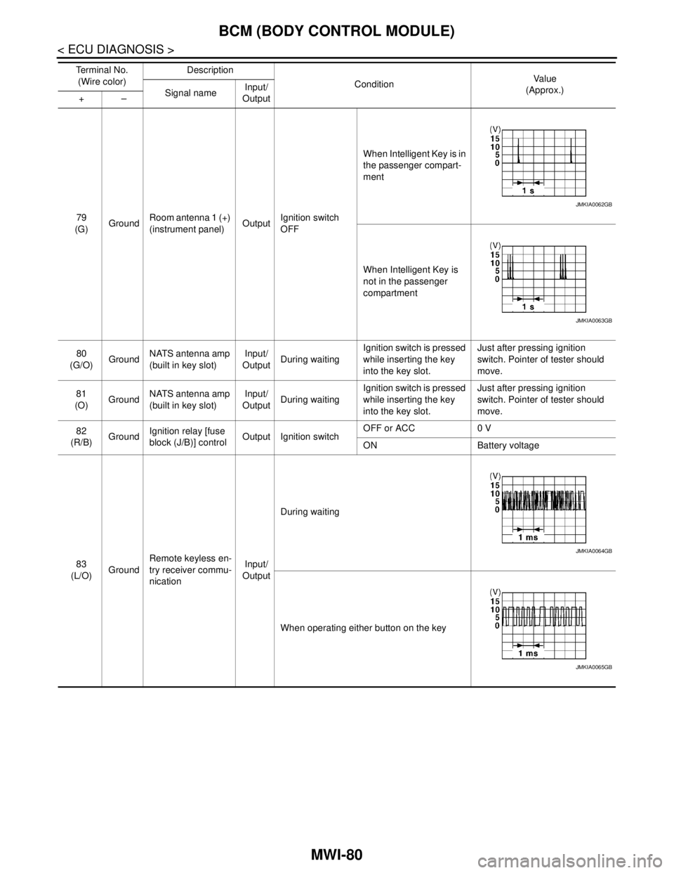
79
(G)GroundRoom antenna 1 (+)
(instrument panel)OutputIgnition switch
OFFWhen Intelligent Key is in
the passenger compart-
ment
When Intelligent Key is
not in the passenger
compartment
80
(G/O)GroundNATS antenna amp
(built in key slot)Input/
OutputDuring waitingIgnition switch is pressed
while inserting the key
into the key slot.Just after pressing ignition
switch. Pointer of tester should
move.
81
(O)GroundNATS antenna amp
(built in key slot)Input/
OutputDuring waitingIgnition switch is pressed
while inserting the key
into the key slot.Just after pressing ignition
switch. Pointer of tester should
move.
82
(R/B)GroundIgnition relay [fuse
block (J/B)] controlOutput Ignition switchOFF or ACC 0 V
ON Battery voltage
83
(L/O)GroundRemote keyless en-
try receiver commu-
nicationInput/
OutputDuring waiting
When operating either button on the key Te r m i n a l N o .
(Wire color)Description
ConditionVa l u e
(Approx.)
Signal nameInput/
Output +–
JMKIA0062GB
JMKIA0063GB
JMKIA0064GB
JMKIA0065GB
Page 3337 of 5121

MWI
BCM (BODY CONTROL MODULE)
MWI-83
< ECU DIAGNOSIS >
C
D
E
F
G
H
I
J
K
L
MB A
O
P
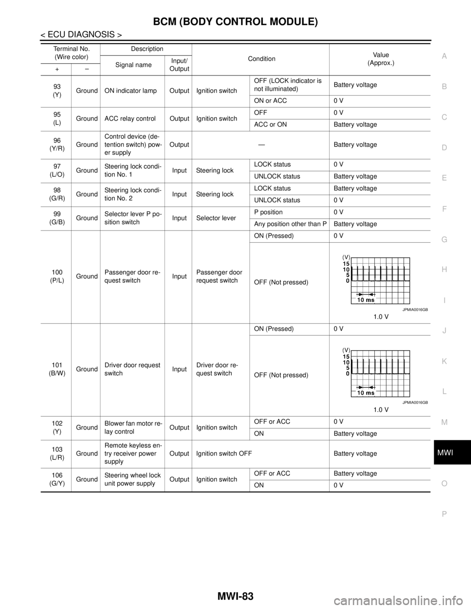
93
(Y)Ground ON indicator lamp Output Ignition switchOFF (LOCK indicator is
not illuminated)Battery voltage
ON or ACC 0 V
95
(L)Ground ACC relay control Output Ignition switchOFF 0 V
ACC or ON Battery voltage
96
(Y/R)GroundControl device (de-
tention switch) pow-
er supplyOutput — Battery voltage
97
(L/O)GroundSteering lock condi-
tion No. 1Input Steering lockLOCK status 0 V
UNLOCK status Battery voltage
98
(G/R)GroundSteering lock condi-
tion No. 2Input Steering lockLOCK status Battery voltage
UNLOCK status 0 V
99
(G/B)GroundSelector lever P po-
sition switchInput Selector leverP position 0 V
Any position other than P Battery voltage
100
(P/L)GroundPassenger door re-
quest switchInputPassenger door
request switchON (Pressed) 0 V
OFF (Not pressed)
1.0 V
101
(B/W)GroundDriver door request
switchInputDriver door re-
quest switchON (Pressed) 0 V
OFF (Not pressed)
1.0 V
102
(Y)GroundBlower fan motor re-
lay controlOutput Ignition switchOFF or ACC 0 V
ON Battery voltage
103
(L/R)GroundRemote keyless en-
try receiver power
supplyOutput Ignition switch OFF Battery voltage
106
(G/Y)GroundSteering wheel lock
unit power supplyOutput Ignition switchOFF or ACC Battery voltage
ON 0 V Te r m i n a l N o .
(Wire color)Description
ConditionVa l u e
(Approx.)
Signal nameInput/
Output +–
JPMIA0016GB
JPMIA0016GB
Page 3476 of 5121
![NISSAN TEANA 2008 Service Manual PCS
BCM (BODY CONTROL MODULE)
PCS-85
< ECU DIAGNOSIS >[POWER DISTRIBUTION SYSTEM]
C
D
E
F
G
H
I
J
K
L B A
O
P N
79
(G)GroundRoom antenna 1 (+)
(instrument panel)OutputIgnition switch
OFFWhen Intelli NISSAN TEANA 2008 Service Manual PCS
BCM (BODY CONTROL MODULE)
PCS-85
< ECU DIAGNOSIS >[POWER DISTRIBUTION SYSTEM]
C
D
E
F
G
H
I
J
K
L B A
O
P N
79
(G)GroundRoom antenna 1 (+)
(instrument panel)OutputIgnition switch
OFFWhen Intelli](/manual-img/5/57391/w960_57391-3475.png)
PCS
BCM (BODY CONTROL MODULE)
PCS-85
< ECU DIAGNOSIS >[POWER DISTRIBUTION SYSTEM]
C
D
E
F
G
H
I
J
K
L B A
O
P N
79
(G)GroundRoom antenna 1 (+)
(instrument panel)OutputIgnition switch
OFFWhen Intelligent Key is in
the passenger compart-
ment
When Intelligent Key is
not in the passenger
compartment
80
(G/O)GroundNATS antenna amp
(built in key slot)Input/
OutputDuring waitingIgnition switch is pressed
while inserting the key
into the key slot.Just after pressing ignition
switch. Pointer of tester should
move.
81
(O)GroundNATS antenna amp
(built in key slot)Input/
OutputDuring waitingIgnition switch is pressed
while inserting the key
into the key slot.Just after pressing ignition
switch. Pointer of tester should
move.
82
(R/B)GroundIgnition relay [fuse
block (J/B)] controlOutput Ignition switchOFF or ACC 0 V
ON Battery voltage
83
(L/O)GroundRemote keyless en-
try receiver commu-
nicationInput/
OutputDuring waiting
When operating either button on the key Te r m i n a l N o .
(Wire color)Description
ConditionVa l u e
(Approx.)
Signal nameInput/
Output +–
JMKIA0062GB
JMKIA0063GB
JMKIA0064GB
JMKIA0065GB
Page 3479 of 5121
![NISSAN TEANA 2008 Service Manual PCS-88
< ECU DIAGNOSIS >[POWER DISTRIBUTION SYSTEM]
BCM (BODY CONTROL MODULE)
93
(Y)Ground ON indicator lamp Output Ignition switchOFF (LOCK indicator is
not illuminated)Battery voltage
ON or ACC 0 V NISSAN TEANA 2008 Service Manual PCS-88
< ECU DIAGNOSIS >[POWER DISTRIBUTION SYSTEM]
BCM (BODY CONTROL MODULE)
93
(Y)Ground ON indicator lamp Output Ignition switchOFF (LOCK indicator is
not illuminated)Battery voltage
ON or ACC 0 V](/manual-img/5/57391/w960_57391-3478.png)
PCS-88
< ECU DIAGNOSIS >[POWER DISTRIBUTION SYSTEM]
BCM (BODY CONTROL MODULE)
93
(Y)Ground ON indicator lamp Output Ignition switchOFF (LOCK indicator is
not illuminated)Battery voltage
ON or ACC 0 V
95
(L)Ground ACC relay control Output Ignition switchOFF 0 V
ACC or ON Battery voltage
96
(Y/R)GroundControl device (de-
tention switch) pow-
er supplyOutput — Battery voltage
97
(L/O)GroundSteering lock condi-
tion No. 1Input Steering lockLOCK status 0 V
UNLOCK status Battery voltage
98
(G/R)GroundSteering lock condi-
tion No. 2Input Steering lockLOCK status Battery voltage
UNLOCK status 0 V
99
(G/B)GroundSelector lever P po-
sition switchInput Selector leverP position 0 V
Any position other than P Battery voltage
100
(P/L)GroundPassenger door re-
quest switchInputPassenger door
request switchON (Pressed) 0 V
OFF (Not pressed)
1.0 V
101
(B/W)GroundDriver door request
switchInputDriver door re-
quest switchON (Pressed) 0 V
OFF (Not pressed)
1.0 V
102
(Y)GroundBlower fan motor re-
lay controlOutput Ignition switchOFF or ACC 0 V
ON Battery voltage
103
(L/R)GroundRemote keyless en-
try receiver power
supplyOutput Ignition switch OFF Battery voltage
106
(G/Y)GroundSteering wheel lock
unit power supplyOutput Ignition switchOFF or ACC Battery voltage
ON 0 V Te r m i n a l N o .
(Wire color)Description
ConditionVa l u e
(Approx.)
Signal nameInput/
Output +–
JPMIA0016GB
JPMIA0016GB