Page 2324 of 5121
![NISSAN TEANA 2008 Service Manual BCM (BODY CONTROL MODULE)
EXL-295
< ECU DIAGNOSIS >[HALOGEN TYPE]
C
D
E
F
G
H
I
J
K
MA
B
EXL
N
O
P
93
(Y)Ground ON indicator lamp Output Ignition switchOFF (LOCK indicator is
not illuminated)Battery NISSAN TEANA 2008 Service Manual BCM (BODY CONTROL MODULE)
EXL-295
< ECU DIAGNOSIS >[HALOGEN TYPE]
C
D
E
F
G
H
I
J
K
MA
B
EXL
N
O
P
93
(Y)Ground ON indicator lamp Output Ignition switchOFF (LOCK indicator is
not illuminated)Battery](/manual-img/5/57391/w960_57391-2323.png)
BCM (BODY CONTROL MODULE)
EXL-295
< ECU DIAGNOSIS >[HALOGEN TYPE]
C
D
E
F
G
H
I
J
K
MA
B
EXL
N
O
P
93
(Y)Ground ON indicator lamp Output Ignition switchOFF (LOCK indicator is
not illuminated)Battery voltage
ON or ACC 0 V
95
(L)Ground ACC relay control Output Ignition switchOFF 0 V
ACC or ON Battery voltage
96
(Y/R)GroundControl device (de-
tention switch) pow-
er supplyOutput — Battery voltage
97
(L/O)GroundSteering lock condi-
tion No. 1Input Steering lockLOCK status 0 V
UNLOCK status Battery voltage
98
(G/R)GroundSteering lock condi-
tion No. 2Input Steering lockLOCK status Battery voltage
UNLOCK status 0 V
99
(G/B)GroundSelector lever P po-
sition switchInput Selector leverP position 0 V
Any position other than P Battery voltage
100
(P/L)GroundPassenger door re-
quest switchInputPassenger door
request switchON (Pressed) 0 V
OFF (Not pressed)
1.0 V
101
(B/W)GroundDriver door request
switchInputDriver door re-
quest switchON (Pressed) 0 V
OFF (Not pressed)
1.0 V
102
(Y)GroundBlower fan motor re-
lay controlOutput Ignition switchOFF or ACC 0 V
ON Battery voltage
103
(L/R)GroundRemote keyless en-
try receiver power
supplyOutput Ignition switch OFF Battery voltage
106
(G/Y)GroundSteering wheel lock
unit power supplyOutput Ignition switchOFF or ACC Battery voltage
ON 0 V Te r m i n a l N o .
(Wire color)Description
ConditionVa l u e
(Approx.)
Signal nameInput/
Output +–
JPMIA0016GB
JPMIA0016GB
Page 2885 of 5121

INL-6
< FUNCTION DIAGNOSIS >
INTERIOR ROOM LAMP CONTROL SYSTEM
The interior room lamp turns ON and OFF (gradual brightening and dimming) by the interior room timer.
BCM judges the vehicle condition with the following items. It activates the interior room timer.
- Ignition switch status
- Door switch signal (ALL)
- Door lock/unlock signal (Remote keyless entry receiver, each request switch, door lock/unlock switch)
NOTE:
Each function of interior room lamp timer can be set by CONSULT-III. Refer to INL-16, "
INT LAMP : CON-
SULT-III Function (BCM - INT LAMP)".
Interior Room Lamp ON Operation
BCM always turns the interior room lamp ON when any door opens.
BCM activates the interior room timer in any of the following conditions to turn the interior room lamp ON for
a period of time.
- Any door opens before all doors close.
- Ignition switch is turned ON → OFF.
- Any door unlock signal is detected when all doors close with ignition switch OFF.
NOTE:
Restart the timer if new condition is input during the timer operating time.
Interior Room Lamp OFF Operation
BCM stops the timer in any of the following conditions to turns the interior room lamp OFF.
The timer operating time is expired.
Ignition switch position is other than OFF with all doors close.
Any door lock operation is detected with all doors close.
STEP LAMP CONTROL
BCM controls the step lamp (ground-side) to turn ON with any door switch ON.
TRUNK ROOM LAMP CONTROL
BCM controls the trunk room lamp (ground-side) to turn ON with trunk room lamp switch ON.
PUSH-BUTTON IGNITION SWITCH ILLUMINATION CONTROL
Push-button Ignition Switch Illumination Basic Operation
BCM provides the power supply to turn the push-button ignition switch illumination ON.
Push-button Ignition Switch Illumination ON Operation
BCM turns the push-button ignition switch illumination ON in the following conditions.
Ignition switch ON
Any of the following conditions with ignition switch OFF
- Engine start permission is entered.
- Intelligent Key inserted into the key slot.
- Driver door is LOCK → UNLOCK.
- Driver door is open.
Push-button Ignition Switch Illumination OFF Operation
BCM turns the push-button ignition switch illumination OFF in any of the following conditions.
The push-button ignition switch illumination ON conditions do not satisfy.
All of the following conditions with ignition switch OFF
- The push-button ignition switch illumination ON conditions do not change (15 seconds after the ignition
switch OFF) or the driver door is UNLOCK → LOCK.
Page 2886 of 5121
INTERIOR ROOM LAMP CONTROL SYSTEM
INL-7
< FUNCTION DIAGNOSIS >
C
D
E
F
G
H
I
J
K
MA
B
INL
N
O
P
Component Parts LocationINFOID:0000000003774541
1. Personal lamp 2. Request switch 3. Step lamp
4. Door switch 5. Door lock/unlock switch 6. Push-button ignition switch illumination
7. Map lamp 8. Remote keyless entry receiver 9. BCM
10. Trunk room lamp switch 11. Trunk room lamp
A. Over the glove box B. Behind the combination meter C. Trunk lid lock assembly
D. Trunk room upward
JPLIA1126ZZ
Page 2887 of 5121
INL-8
< FUNCTION DIAGNOSIS >
INTERIOR ROOM LAMP CONTROL SYSTEM
Component Description
INFOID:0000000003774542
Part Description
BCM Activates the interior room lamp timer depending on the vehicle condition to turn the
interior room lamp ON/OFF.
Turns the step lamp ON/OFF according to any door switch status.
Remote keyless entry receiver Receives the lock/unlock signal from keyfob.
Transmits the lock/unlock signal to BCM.
Request switch
Door lock/unlock switchInputs the lock/unlock signal to BCM.
Door switch
Trunk room lamp switchInputs the switch signal to BCM.
Page 2888 of 5121

INTERIOR ROOM LAMP BATTERY SAVER SYSTEM
INL-9
< FUNCTION DIAGNOSIS >
C
D
E
F
G
H
I
J
K
MA
B
INL
N
O
P
INTERIOR ROOM LAMP BATTERY SAVER SYSTEM
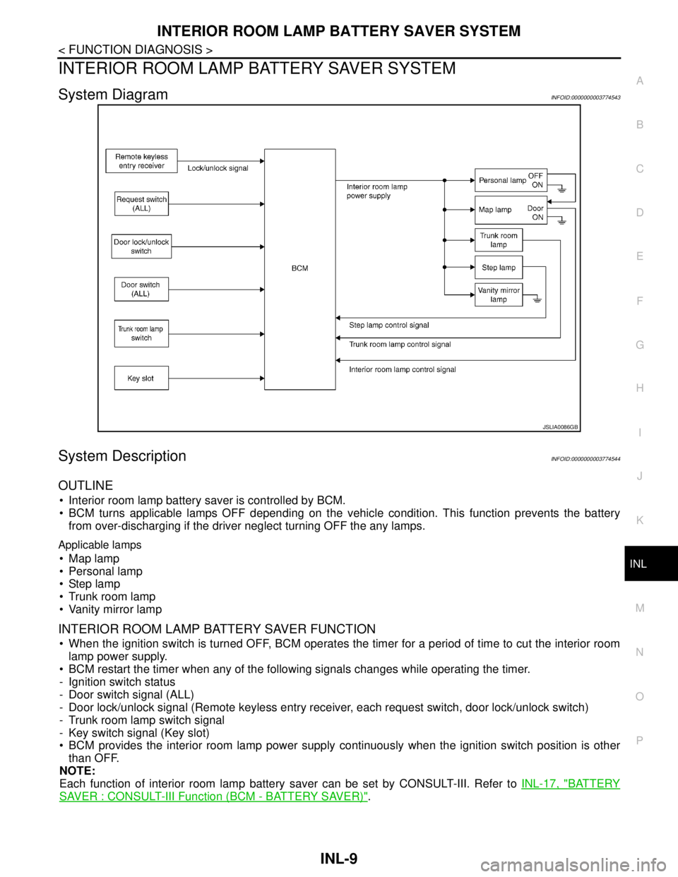
System DiagramINFOID:0000000003774543
System DescriptionINFOID:0000000003774544
OUTLINE
Interior room lamp battery saver is controlled by BCM.
BCM turns applicable lamps OFF depending on the vehicle condition. This function prevents the battery
from over-discharging if the driver neglect turning OFF the any lamps.
Applicable lamps
Map lamp
Personal lamp
Step lamp
Trunk room lamp
Vanity mirror lamp
INTERIOR ROOM LAMP BATTERY SAVER FUNCTION
When the ignition switch is turned OFF, BCM operates the timer for a period of time to cut the interior room
lamp power supply.
BCM restart the timer when any of the following signals changes while operating the timer.
- Ignition switch status
- Door switch signal (ALL)
- Door lock/unlock signal (Remote keyless entry receiver, each request switch, door lock/unlock switch)
- Trunk room lamp switch signal
- Key switch signal (Key slot)
BCM provides the interior room lamp power supply continuously when the ignition switch position is other
than OFF.
NOTE:
Each function of interior room lamp battery saver can be set by CONSULT-III. Refer to INL-17, "
BATTERY
SAVER : CONSULT-III Function (BCM - BATTERY SAVER)".
JSLIA0086GB
Page 2896 of 5121

DIAGNOSIS SYSTEM (BCM)
INL-17
< FUNCTION DIAGNOSIS >
C
D
E
F
G
H
I
J
K
MA
B
INL
N
O
P
ACTIVE TEST
BATTERY SAVER
BATTERY SAVER : CONSULT-III Function (BCM - BATTERY SAVER)INFOID:0000000003774553
WORK SUPPORT
*: Factory setting
DATA MONITOR
DOOR SW-DR
[On/Off]The switch status input from front door switch (driver side)
DOOR SW-AS
[On/Off]The switch status input from front door switch (passenger side)
DOOR SW-RR
[On/Off]The switch status input from rear door switch RH
DOOR SW- RL
[On/Off]The switch status input from rear door switch LH
DOOR SW-BK
[On/Off]NOTE:
The item is indicated, but not monitored.
CDL LOCK SW
[On/Off]Lock switch status received from door lock/unlock switch
CDL UNLOCK SW
[On/Off]Unlock switch status received from door lock/unlock switch
KEY CYL LK-SW
[On/Off]NOTE:
The item is indicated, but not monitored.
KEY CYL UN-SW
[On/Off]NOTE:
The item is indicated, but not monitored.
TRNK/HAT MNTR
[On/Off]The switch status input from trunk room lamp switch
RKE-LOCK
[On/Off]Lock signal status received from remote keyless entry receiver
RKE-UNLOCK
[On/Off]Unlock signal status received from remote keyless entry receiver Monitor item
[Unit]Description
Test item Operation Description
INT LAMPOnOutputs the interior room lamp control signal to turn map lamp and personal lamp ON
(Map lamp switch is in DOOR position).
Off Stops the interior room lamp control signal to turn map lamp and personal lamp OFF.
STEP LAMP TESTOn Outputs the step lamp control signal to turn step lamp ON.
Off Stops the step lamp control signal to turn step lamp OFF.
LUGGAGE LAMP TESTOn Outputs the trunk room lamp control signal to turn trunk room lamp ON.
Off Stops the trunk room lamp control signal to turn trunk room lamp OFF.
Service item Setting item Setting
BATTERY SAVER SETOn* With the exterior lamp battery saver function
Off Without the exterior lamp battery saver function
ROOM LAMP BAT SAV SETOn* With the interior room lamp battery saver function
Off Without the interior room lamp battery saver function
ROOM LAMP TIMER SETMODE 1* 30 min.
Sets the interior room lamp battery saver timer operating
time.
MODE 2 60 min.
Page 2944 of 5121

BCM (BODY CONTROL MODULE)
INL-65
< ECU DIAGNOSIS >
C
D
E
F
G
H
I
J
K
MA
B
INL
N
O
P
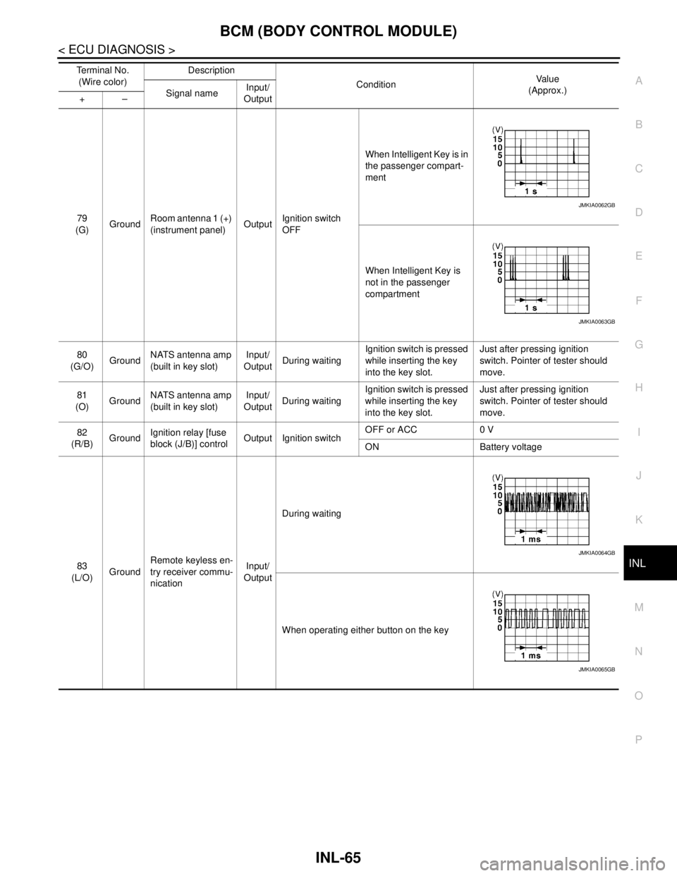
79
(G)GroundRoom antenna 1 (+)
(instrument panel)OutputIgnition switch
OFFWhen Intelligent Key is in
the passenger compart-
ment
When Intelligent Key is
not in the passenger
compartment
80
(G/O)GroundNATS antenna amp
(built in key slot)Input/
OutputDuring waitingIgnition switch is pressed
while inserting the key
into the key slot.Just after pressing ignition
switch. Pointer of tester should
move.
81
(O)GroundNATS antenna amp
(built in key slot)Input/
OutputDuring waitingIgnition switch is pressed
while inserting the key
into the key slot.Just after pressing ignition
switch. Pointer of tester should
move.
82
(R/B)GroundIgnition relay [fuse
block (J/B)] controlOutput Ignition switchOFF or ACC 0 V
ON Battery voltage
83
(L/O)GroundRemote keyless en-
try receiver commu-
nicationInput/
OutputDuring waiting
When operating either button on the key Te r m i n a l N o .
(Wire color)Description
ConditionVa l u e
(Approx.)
Signal nameInput/
Output +–
JMKIA0062GB
JMKIA0063GB
JMKIA0064GB
JMKIA0065GB
Page 2947 of 5121

INL-68
< ECU DIAGNOSIS >
BCM (BODY CONTROL MODULE)
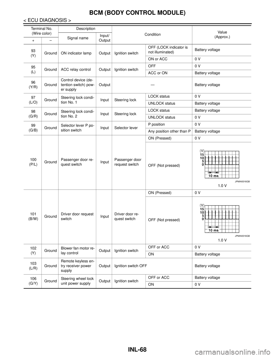
93
(Y)Ground ON indicator lamp Output Ignition switchOFF (LOCK indicator is
not illuminated)Battery voltage
ON or ACC 0 V
95
(L)Ground ACC relay control Output Ignition switchOFF 0 V
ACC or ON Battery voltage
96
(Y/R)GroundControl device (de-
tention switch) pow-
er supplyOutput — Battery voltage
97
(L/O)GroundSteering lock condi-
tion No. 1Input Steering lockLOCK status 0 V
UNLOCK status Battery voltage
98
(G/R)GroundSteering lock condi-
tion No. 2Input Steering lockLOCK status Battery voltage
UNLOCK status 0 V
99
(G/B)GroundSelector lever P po-
sition switchInput Selector leverP position 0 V
Any position other than P Battery voltage
100
(P/L)GroundPassenger door re-
quest switchInputPassenger door
request switchON (Pressed) 0 V
OFF (Not pressed)
1.0 V
101
(B/W)GroundDriver door request
switchInputDriver door re-
quest switchON (Pressed) 0 V
OFF (Not pressed)
1.0 V
102
(Y)GroundBlower fan motor re-
lay controlOutput Ignition switchOFF or ACC 0 V
ON Battery voltage
103
(L/R)GroundRemote keyless en-
try receiver power
supplyOutput Ignition switch OFF Battery voltage
106
(G/Y)GroundSteering wheel lock
unit power supplyOutput Ignition switchOFF or ACC Battery voltage
ON 0 V Te r m i n a l N o .
(Wire color)Description
ConditionVa l u e
(Approx.)
Signal nameInput/
Output +–
JPMIA0016GB
JPMIA0016GB