2008 NISSAN TEANA remote control
[x] Cancel search: remote controlPage 1188 of 5121

DEF-38
< ECU DIAGNOSIS >
BCM (BODY CONTROL MODULE)
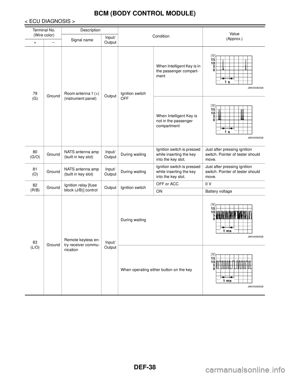
79
(G)GroundRoom antenna 1 (+)
(instrument panel)OutputIgnition switch
OFFWhen Intelligent Key is in
the passenger compart-
ment
When Intelligent Key is
not in the passenger
compartment
80
(G/O)GroundNATS antenna amp
(built in key slot)Input/
OutputDuring waitingIgnition switch is pressed
while inserting the key
into the key slot.Just after pressing ignition
switch. Pointer of tester should
move.
81
(O)GroundNATS antenna amp
(built in key slot)Input/
OutputDuring waitingIgnition switch is pressed
while inserting the key
into the key slot.Just after pressing ignition
switch. Pointer of tester should
move.
82
(R/B)GroundIgnition relay [fuse
block (J/B)] controlOutput Ignition switchOFF or ACC 0 V
ON Battery voltage
83
(L/O)GroundRemote keyless en-
try receiver commu-
nicationInput/
OutputDuring waiting
When operating either button on the key Te r m i n a l N o .
(Wire color)Description
ConditionVa l u e
(Approx.)
Signal nameInput/
Output +–
JMKIA0062GB
JMKIA0063GB
JMKIA0064GB
JMKIA0065GB
Page 1191 of 5121

BCM (BODY CONTROL MODULE)
DEF-41
< ECU DIAGNOSIS >
C
D
E
F
G
H
I
J
K
MA
B
DEF
N
O
P
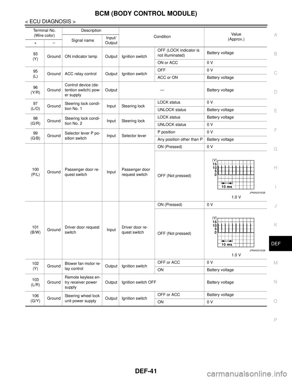
93
(Y)Ground ON indicator lamp Output Ignition switchOFF (LOCK indicator is
not illuminated)Battery voltage
ON or ACC 0 V
95
(L)Ground ACC relay control Output Ignition switchOFF 0 V
ACC or ON Battery voltage
96
(Y/R)GroundControl device (de-
tention switch) pow-
er supplyOutput — Battery voltage
97
(L/O)GroundSteering lock condi-
tion No. 1Input Steering lockLOCK status 0 V
UNLOCK status Battery voltage
98
(G/R)GroundSteering lock condi-
tion No. 2Input Steering lockLOCK status Battery voltage
UNLOCK status 0 V
99
(G/B)GroundSelector lever P po-
sition switchInput Selector leverP position 0 V
Any position other than P Battery voltage
100
(P/L)GroundPassenger door re-
quest switchInputPassenger door
request switchON (Pressed) 0 V
OFF (Not pressed)
1.0 V
101
(B/W)GroundDriver door request
switchInputDriver door re-
quest switchON (Pressed) 0 V
OFF (Not pressed)
1.0 V
102
(Y)GroundBlower fan motor re-
lay controlOutput Ignition switchOFF or ACC 0 V
ON Battery voltage
103
(L/R)GroundRemote keyless en-
try receiver power
supplyOutput Ignition switch OFF Battery voltage
106
(G/Y)GroundSteering wheel lock
unit power supplyOutput Ignition switchOFF or ACC Battery voltage
ON 0 V Te r m i n a l N o .
(Wire color)Description
ConditionVa l u e
(Approx.)
Signal nameInput/
Output +–
JPMIA0016GB
JPMIA0016GB
Page 1217 of 5121

DLK-1
BODY EXTERIOR, DOORS, ROOF & VEHICLE SECURITY
C
D
E
F
G H
I
J
L
M
SECTION DLK
A
B
DLK
N
O P
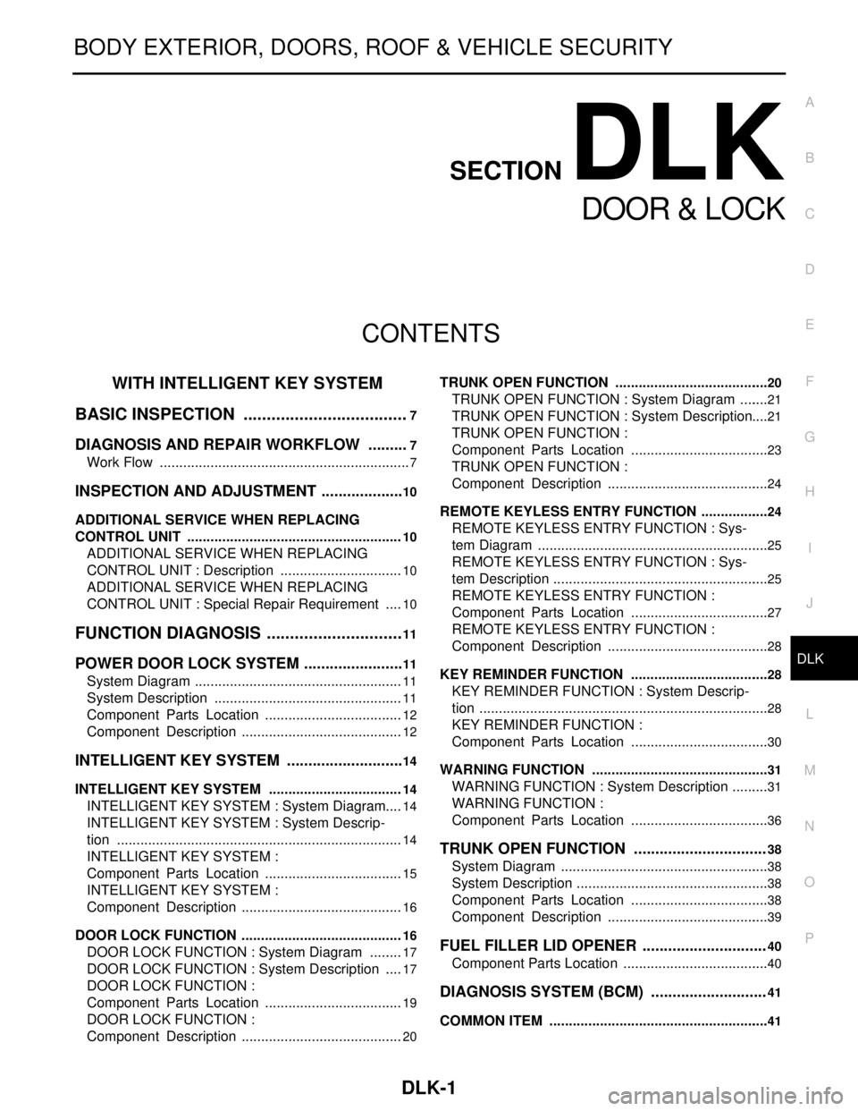
CONTENTS
DOOR & LOCK
WITH INTELLIGE NT KEY SYSTEM
BASIC INSPECTION ....... .............................
7
DIAGNOSIS AND REPAIR WORKFLOW ..... .....7
Work Flow ........................................................... ......7
INSPECTION AND ADJUSTMENT ....................10
ADDITIONAL SERVICE WHEN REPLACING
CONTROL UNIT .................................................... ....
10
ADDITIONAL SERVICE WHEN REPLACING
CONTROL UNIT : Description ................................
10
ADDITIONAL SERVICE WHEN REPLACING
CONTROL UNIT : Special Repair Requirement .....
10
FUNCTION DIAGNOSIS .. ............................11
POWER DOOR LOCK SYSTEM .................... ....11
System Diagram .................................................. ....11
System Description .................................................11
Component Parts Location ....................................12
Component Description ..........................................12
INTELLIGENT KEY SYSTEM ............................14
INTELLIGENT KEY SYSTEM ...................................14
INTELLIGENT KEY SYSTEM : System Diagram ....14
INTELLIGENT KEY SYSTEM : System Descrip-
tion ..........................................................................
14
INTELLIGENT KEY SYSTEM :
Component Parts Location ....................................
15
INTELLIGENT KEY SYSTEM :
Component Description ..........................................
16
DOOR LOCK FUNCTION ...................................... ....16
DOOR LOCK FUNCTION : System Diagram .........17
DOOR LOCK FUNCTION : System Description .....17
DOOR LOCK FUNCTION :
Component Parts Location ....................................
19
DOOR LOCK FUNCTION :
Component Description ..........................................
20
TRUNK OPEN FUNCTION .................................... ....20
TRUNK OPEN FUNCTION : System Diagram ........21
TRUNK OPEN FUNCTION : System Description ....21
TRUNK OPEN FUNCTION :
Component Parts Location ....................................
23
TRUNK OPEN FUNCTION :
Component Description ..........................................
24
REMOTE KEYLESS ENTRY FUNCTION ..................24
REMOTE KEYLESS ENTRY FUNCTION : Sys-
tem Diagram ........................................................ ....
25
REMOTE KEYLESS ENTRY FUNCTION : Sys-
tem Description ........................................................
25
REMOTE KEYLESS ENTRY FUNCTION :
Component Parts Location ....................................
27
REMOTE KEYLESS ENTRY FUNCTION :
Component Description ..........................................
28
KEY REMINDER FUNCTION ................................ ....28
KEY REMINDER FUNCTION : System Descrip-
tion ...........................................................................
28
KEY REMINDER FUNCTION :
Component Parts Location ....................................
30
WARNING FUNCTION .......................................... ....31
WARNING FUNCTION : System Description ..........31
WARNING FUNCTION :
Component Parts Location ................................ ....
36
TRUNK OPEN FUNCTION ...............................38
System Diagram ......................................................38
System Description ..................................................38
Component Parts Location ....................................38
Component Description ..........................................39
FUEL FILLER LID OPENER .............................40
Component Parts Location ......................................40
DIAGNOSIS SYSTEM (BCM) ...........................41
COMMON ITEM ..................................................... ....41
Page 1218 of 5121

DLK-2
COMMON ITEM : CONSULT-III Function (BCM -
COMMON ITEM) ....................................................
41
DOOR LOCK .............................................................42
DOOR LOCK : CONSULT-III Function (BCM -
DOOR LOCK) .........................................................
42
INTELLIGENT KEY ...................................................43
INTELLIGENT KEY : CONSULT-III Function
(BCM - INTELLIGENT KEY) ...................................
43
TRUNK ......................................................................46
TRUNK : CONSULT-III Function (BCM - TRUNK) ...46
COMPONENT DIAGNOSIS ........................48
U1000 CAN COMM CIRCUIT ............................48
BCM ...........................................................................48
BCM : Description ...................................................48
BCM : DTC Logic ....................................................48
BCM : Diagnosis Procedure ...................................48
U1010 CONTROL UNIT (CAN) .........................49
BCM ...........................................................................49
BCM : DTC Logic ....................................................49
BCM : Diagnosis Procedure ...................................49
BCM : Special Repair Requirement ........................49
B2621 INSIDE KEY ANTENNA 1 ......................50
Description ..............................................................50
DTC Logic ...............................................................50
Diagnosis Procedure ..............................................50
B2622 INSIDE KEY ANTENNA 2 ......................52
Description ..............................................................52
DTC Logic ...............................................................52
Diagnosis Procedure ..............................................52
B2623 INSIDE KEY ANTENNA 3 ......................54
Description ..............................................................54
DTC Logic ...............................................................54
Diagnosis Procedure ..............................................54
POWER SUPPLY AND GROUND CIRCUIT .....56
BCM (BODY CONTROL MODULE) .........................56
BCM (BODY CONTROL MODULE) : Diagnosis
Procedure ...............................................................
56
DOOR SWITCH .................................................57
Description ..............................................................57
Component Function Check .................................57
Diagnosis Procedure ..............................................57
Component Inspection ............................................59
DOOR LOCK AND UNLOCK SWITCH .............60
Description ..............................................................60
Component Function Check .................................60
Diagnosis Procedure ..............................................60
DOOR LOCK ACTUATOR ................................61
DRIVER SIDE ............................................................61
DRIVER SIDE : Description ....................................61
DRIVER SIDE : Component Function Check ........61
DRIVER SIDE : Diagnosis Procedure .....................61
PASSENGER SIDE ...................................................61
PASSENGER SIDE : Description ...........................62
PASSENGER SIDE :
Component Function Check ..................................
62
PASSENGER SIDE : Diagnosis Procedure ............62
REAR LH ...................................................................62
REAR LH : Description ...........................................62
REAR LH : Component Function Check ...............63
REAR LH : Diagnosis Procedure ............................63
REAR RH ...................................................................63
REAR RH : Description ...........................................63
REAR RH : Component Function Check ...............63
REAR RH : Diagnosis Procedure ...........................64
TRUNK LID OPENER ACTUATOR ..................65
Description ..............................................................65
Component Function Check ..................................65
Diagnosis Procedure ...............................................65
REMOTE KEYLESS ENTRY RECEIVER .........67
Description ..............................................................67
Component Function Check ..................................67
Diagnosis Procedure ...............................................67
TRUNK LID OPENER SWITCH ........................70
Description ..............................................................70
Component Function Check ..................................70
Diagnosis Procedure ...............................................70
Component Inspection ............................................71
DOOR REQUEST SWITCH ...............................72
Description ..............................................................72
Component Function Check ..................................72
Diagnosis Procedure ...............................................72
Component Inspection ............................................73
TRUNK LID OPENER REQUEST SWITCH ......74
Description ..............................................................74
Component Function Check ..................................74
Diagnosis Procedure ...............................................74
Component Inspection ............................................75
TRUNK ROOM LAMP SWITCH ........................76
Description ..............................................................76
Component Function Check ..................................76
Diagnosis Procedure ...............................................76
Component Inspection ............................................77
UNLOCK SENSOR ............................................78
Description ..............................................................78
Component Function Check ..................................78
Diagnosis Procedure ...............................................78
Component Inspection ............................................79
OUTSIDE KEY ANTENNA ................................80
Page 1230 of 5121
![NISSAN TEANA 2008 Service Manual DLK-14
< FUNCTION DIAGNOSIS >[WITH INTELLIGENT KEY SYSTEM]
INTELLIGENT KEY SYSTEM
INTELLIGENT KEY SYSTEM
INTELLIGENT KEY SYSTEM
INTELLIGENT KEY SYSTEM : System DiagramINFOID:0000000003794738
INTELLIGE NISSAN TEANA 2008 Service Manual DLK-14
< FUNCTION DIAGNOSIS >[WITH INTELLIGENT KEY SYSTEM]
INTELLIGENT KEY SYSTEM
INTELLIGENT KEY SYSTEM
INTELLIGENT KEY SYSTEM
INTELLIGENT KEY SYSTEM : System DiagramINFOID:0000000003794738
INTELLIGE](/manual-img/5/57391/w960_57391-1229.png)
DLK-14
< FUNCTION DIAGNOSIS >[WITH INTELLIGENT KEY SYSTEM]
INTELLIGENT KEY SYSTEM
INTELLIGENT KEY SYSTEM
INTELLIGENT KEY SYSTEM
INTELLIGENT KEY SYSTEM : System DiagramINFOID:0000000003794738
INTELLIGENT KEY SYSTEM : System DescriptionINFOID:0000000003794739
The Intelligent Key system is a system that makes it possible to lock and unlock the door locks (door lock/
unlock function) by carrying the Intelligent Key, which operates based on the results of electronic ID verifica-
tion using two-way communications between the Intelligent Key and the vehicle (BCM).
CAUTION:
The driver should always carry the Intelligent Key
The settings for each function can be changed with the CONSULT-III.
If an Intelligent Key is lost, a new Intelligent Key can be registered. A maximum of 4 Intelligent Keys can be
registered.
It is possible to perform a diagnosis on the system and register an Intelligent Key with CONSULT-III.
JMKIA2374GB
Function Description Refer
Door lock function Lock/unlock can be performed by pressing the request switch. DLK-17
Remote keyless entry func-
tionLock/unlock can be performed by pressing the remote controller button of the In-
telligent Key. DLK-25
Trunk lid open functionThe trunk lid can be opened by carrying the Intelligent Key and pressing the
trunk lid opener request switch. DLK-21
Key reminder functionThe key reminder buzzer sounds a warning if the door is locked with the key left
inside the vehicle. DLK-28
Warning functionIf an action that does not meet the operating condition of the Intelligent Key sys-
tem is taken, the buzzer sounds to inform the driver.DLK-31
Engine start function The engine be turned on while carrying the Intelligent Key. SEC-9
Page 1231 of 5121
![NISSAN TEANA 2008 Service Manual INTELLIGENT KEY SYSTEM
DLK-15
< FUNCTION DIAGNOSIS >[WITH INTELLIGENT KEY SYSTEM]
C
D
E
F
G
H
I
J
L
MA
B
DLK
N
O
P
INTELLIGENT KEY SYSTEM : Component Parts LocationINFOID:0000000003794740
1. BCM M118, NISSAN TEANA 2008 Service Manual INTELLIGENT KEY SYSTEM
DLK-15
< FUNCTION DIAGNOSIS >[WITH INTELLIGENT KEY SYSTEM]
C
D
E
F
G
H
I
J
L
MA
B
DLK
N
O
P
INTELLIGENT KEY SYSTEM : Component Parts LocationINFOID:0000000003794740
1. BCM M118,](/manual-img/5/57391/w960_57391-1230.png)
INTELLIGENT KEY SYSTEM
DLK-15
< FUNCTION DIAGNOSIS >[WITH INTELLIGENT KEY SYSTEM]
C
D
E
F
G
H
I
J
L
MA
B
DLK
N
O
P
INTELLIGENT KEY SYSTEM : Component Parts LocationINFOID:0000000003794740
1. BCM M118, M119, M120, M121,
M122, M1232. TCM F23 3. IPDM E/R E10, E11
4. Intelligent Key warning buzzer E25 5. Remote keyless entry receiver M78 6. Combination meter M34
7. Key slot M99 8. Control device (detention switch)
M579. Inside key antenna (console) M262
JMKIA2375ZZ
Page 1232 of 5121
![NISSAN TEANA 2008 Service Manual DLK-16
< FUNCTION DIAGNOSIS >[WITH INTELLIGENT KEY SYSTEM]
INTELLIGENT KEY SYSTEM
INTELLIGENT KEY SYSTEM : Component Description
INFOID:0000000003794741
DOOR LOCK FUNCTION
10. Inside key antenna (inst NISSAN TEANA 2008 Service Manual DLK-16
< FUNCTION DIAGNOSIS >[WITH INTELLIGENT KEY SYSTEM]
INTELLIGENT KEY SYSTEM
INTELLIGENT KEY SYSTEM : Component Description
INFOID:0000000003794741
DOOR LOCK FUNCTION
10. Inside key antenna (inst](/manual-img/5/57391/w960_57391-1231.png)
DLK-16
< FUNCTION DIAGNOSIS >[WITH INTELLIGENT KEY SYSTEM]
INTELLIGENT KEY SYSTEM
INTELLIGENT KEY SYSTEM : Component Description
INFOID:0000000003794741
DOOR LOCK FUNCTION
10. Inside key antenna (instrument cen-
ter) M10511. Inside key antenna (trunk room) B86 12. Outside key antenna (rear bumper)
D85
13. Front outside handle LH (request
switch) D1114. Front outside handle LH
(outside key antenna) D1215. Trunk lid lock assembly
(trunk lid opener actuator) T5
16. Front door switch (driver side) B34
A. Behind the combination meter B. Engine room (LH) C. Behind the instrument lower panel
RH
D. Behind the center console E. Behind the audio unit F. View with rear bumper removed
1. Front door lock assembly (driver
side) D92. Rear door lock assembly LH D85 3. Trunk lid opener request switch T6
A. View with front door finisher removed B. View with rear door finisher removed C. View with trunk lid
JMKIA2376ZZ
Item Function
BCM Controls the Intelligent Key system.
Front door lock assembly (door lock
actuator)Outputs lock/unlock signal from BCM and locks/unlocks each door.
Front door lock assembly (unlock
sensor)Detects door lock condition of driver door.
Door switch Inputs door open/close condition to BCM.
Remote keyless entry receiver Receives lock/unlock signal from the Intelligent Key, and then transmits to BCM.
Request switch Inputs lock/unlock operation to BCM.
Intelligent Key Transmits button operation to remote keyless entry receiver.
Outside key antenna Detects if Intelligent Key is outside the vehicle.
Inside key antenna Detects if Intelligent Key is inside the vehicle.
Intelligent Key warning buzzer Warns the user of the lock/unlock condition and inappropriate operations with the buzzer sound.
Page 1235 of 5121
![NISSAN TEANA 2008 Service Manual INTELLIGENT KEY SYSTEM
DLK-19
< FUNCTION DIAGNOSIS >[WITH INTELLIGENT KEY SYSTEM]
C
D
E
F
G
H
I
J
L
MA
B
DLK
N
O
P
DOOR LOCK FUNCTION : Component Parts LocationINFOID:0000000003841720
1. BCM M118, M11 NISSAN TEANA 2008 Service Manual INTELLIGENT KEY SYSTEM
DLK-19
< FUNCTION DIAGNOSIS >[WITH INTELLIGENT KEY SYSTEM]
C
D
E
F
G
H
I
J
L
MA
B
DLK
N
O
P
DOOR LOCK FUNCTION : Component Parts LocationINFOID:0000000003841720
1. BCM M118, M11](/manual-img/5/57391/w960_57391-1234.png)
INTELLIGENT KEY SYSTEM
DLK-19
< FUNCTION DIAGNOSIS >[WITH INTELLIGENT KEY SYSTEM]
C
D
E
F
G
H
I
J
L
MA
B
DLK
N
O
P
DOOR LOCK FUNCTION : Component Parts LocationINFOID:0000000003841720
1. BCM M118, M119, M120, M121,
M122, M1232. TCM F23 3. IPDM E/R E10, E11
4. Intelligent Key warning buzzer E25 5. Remote keyless entry receiver M78 6. Combination meter M34
7. Key slot M99 8. Control device (detention switch)
M579. Inside key antenna (console) M262
JMKIA2375ZZ