2008 NISSAN TEANA air filter
[x] Cancel search: air filterPage 4006 of 5121
![NISSAN TEANA 2008 Service Manual SE-142
< ON-VEHICLE REPAIR >[WITHOUT VENTILATION SEAT]
REAR SEAT
Removal and Installation
INFOID:0000000003840027
REMOVAL
CAUTION:
When removing and installing, use shop cloths to protect parts from d NISSAN TEANA 2008 Service Manual SE-142
< ON-VEHICLE REPAIR >[WITHOUT VENTILATION SEAT]
REAR SEAT
Removal and Installation
INFOID:0000000003840027
REMOVAL
CAUTION:
When removing and installing, use shop cloths to protect parts from d](/manual-img/5/57391/w960_57391-4005.png)
SE-142
< ON-VEHICLE REPAIR >[WITHOUT VENTILATION SEAT]
REAR SEAT
Removal and Installation
INFOID:0000000003840027
REMOVAL
CAUTION:
When removing and installing, use shop cloths to protect parts from damage.
1. Remove the headrest.
2. Remove the seat cushion.
Pull the lock lever (1) at the front bottom of the seat cushion
forward (1 for each side), and pull the seat cushion upward to
release the wire (2) from the seat cushion hook. Then pull the
seat cushion forward to remove.
Remove the seat cushion from the vehicle.
3. Remove the seatback.
Remove the bolts under seatback.
Lift up seatback from underneath, and then remove seatback from seatback hook that is fixed to the
vehicle.
Remove the seatback from the vehicle.
INSTALLATION
Install in the reverse order of removal.
CAUTION:
When removing and installing, use shop cloths to protect parts from damage.
Disassembly and AssemblyINFOID:0000000003840028
SEATBACK
Disassembly
1. Remove armrest assembly.
Remove the pawls, and pull out the cup holder.
19. Seatback center pad 20. Seat cushion heater unit 21. Seatback heater unit
22. Seatback pad 23. Seatback trim 24. Seat belt hook
25. Headrest holder (locked) 26. Headrest holder (free) 27. Headrest side (long type)
28. Headrest side (normal type) 29. Headrest center (normal type) 30. Headrest center (long type)
31. Seatback duct C 32. Seatback duct B 33. Ventilation motor (seatback)
34. Blower filter 35. Seatback duct A 36. Ventilation seat control unit
Refer to GI-4, "
Components" for symbols in the figure.
JMJIA0251ZZ
: Pawl
JMJIA1936ZZ
Page 4275 of 5121
SRC-32
< COMPONENT DIAGNOSIS >
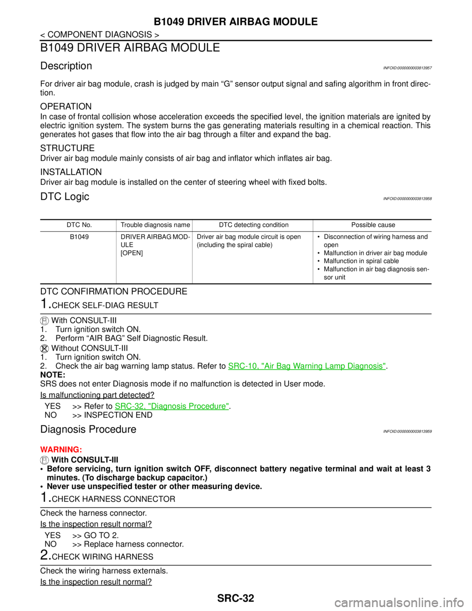
B1049 DRIVER AIRBAG MODULE
B1049 DRIVER AIRBAG MODULE
DescriptionINFOID:0000000003813957
For driver air bag module, crash is judged by main “G” sensor output signal and safing algorithm in front direc-
tion.
OPERATION
In case of frontal collision whose acceleration exceeds the specified level, the ignition materials are ignited by
electric ignition system. The system burns the gas generating materials resulting in a chemical reaction. This
generates hot gases that flow into the air bag through a filter and expand the bag.
STRUCTURE
Driver air bag module mainly consists of air bag and inflator which inflates air bag.
INSTALLATION
Driver air bag module is installed on the center of steering wheel with fixed bolts.
DTC LogicINFOID:0000000003813958
DTC CONFIRMATION PROCEDURE
1.CHECK SELF-DIAG RESULT
With CONSULT-III
1. Turn ignition switch ON.
2. Perform “AIR BAG” Self Diagnostic Result.
Without CONSULT-III
1. Turn ignition switch ON.
2. Check the air bag warning lamp status. Refer to SRC-10, "
Air Bag Warning Lamp Diagnosis".
NOTE:
SRS does not enter Diagnosis mode if no malfunction is detected in User mode.
Is malfunctioning part detected?
YES >> Refer to SRC-32, "Diagnosis Procedure".
NO >> INSPECTION END
Diagnosis ProcedureINFOID:0000000003813959
WARNING:
With CONSULT-III
Before servicing, turn ignition switch OFF, disconnect battery negative terminal and wait at least 3
minutes. (To discharge backup capacitor.)
Never use unspecified tester or other measuring device.
1.CHECK HARNESS CONNECTOR
Check the harness connector.
Is the inspection result normal?
YES >> GO TO 2.
NO >> Replace harness connector.
2.CHECK WIRING HARNESS
Check the wiring harness externals.
Is the inspection result normal?
DTC No. Trouble diagnosis name DTC detecting condition Possible cause
B1049 DRIVER AIRBAG MOD-
ULE
[OPEN]Driver air bag module circuit is open
(including the spiral cable) Disconnection of wiring harness and
open
Malfunction in driver air bag module
Malfunction in spiral cable
Malfunction in air bag diagnosis sen-
sor unit
Page 4277 of 5121
SRC-34
< COMPONENT DIAGNOSIS >
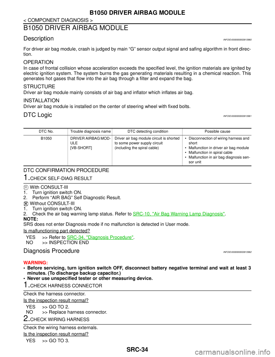
B1050 DRIVER AIRBAG MODULE
B1050 DRIVER AIRBAG MODULE
DescriptionINFOID:0000000003813960
For driver air bag module, crash is judged by main “G” sensor output signal and safing algorithm in front direc-
tion.
OPERATION
In case of frontal collision whose acceleration exceeds the specified level, the ignition materials are ignited by
electric ignition system. The system burns the gas generating materials resulting in a chemical reaction. This
generates hot gases that flow into the air bag through a filter and expand the bag.
STRUCTURE
Driver air bag module mainly consists of air bag and inflator which inflates air bag.
INSTALLATION
Driver air bag module is installed on the center of steering wheel with fixed bolts.
DTC LogicINFOID:0000000003813961
DTC CONFIRMATION PROCEDURE
1.CHECK SELF-DIAG RESULT
With CONSULT-III
1. Turn ignition switch ON.
2. Perform “AIR BAG” Self Diagnostic Result.
Without CONSULT-III
1. Turn ignition switch ON.
2. Check the air bag warning lamp status. Refer to SRC-10, "
Air Bag Warning Lamp Diagnosis".
NOTE:
SRS does not enter Diagnosis mode if no malfunction is detected in User mode.
Is malfunctioning part detected?
YES >> Refer to SRC-34, "Diagnosis Procedure".
NO >> INSPECTION END
Diagnosis ProcedureINFOID:0000000003813962
WARNING:
Before servicing, turn ignition switch OFF, disconnect battery negative terminal and wait at least 3
minutes. (To discharge backup capacitor.)
Never use unspecified tester or other measuring device.
1.CHECK HARNESS CONNECTOR
Check the harness connector.
Is the inspection result normal?
YES >> GO TO 2.
NO >> Replace harness connector.
2.CHECK WIRING HARNESS
Check the wiring harness externals.
Is the inspection result normal?
YES >> GO TO 3.
DTC No. Trouble diagnosis name DTC detecting condition Possible cause
B1050 DRIVER AIRBAG MOD-
ULE
[VB-SHORT]Driver air bag module circuit is shorted
to some power supply circuit
(including the spiral cable) Disconnection of wiring harness and
short
Malfunction in driver air bag module
Malfunction in spiral cable
Malfunction in air bag diagnosis sen-
sor unit
Page 4279 of 5121
SRC-36
< COMPONENT DIAGNOSIS >
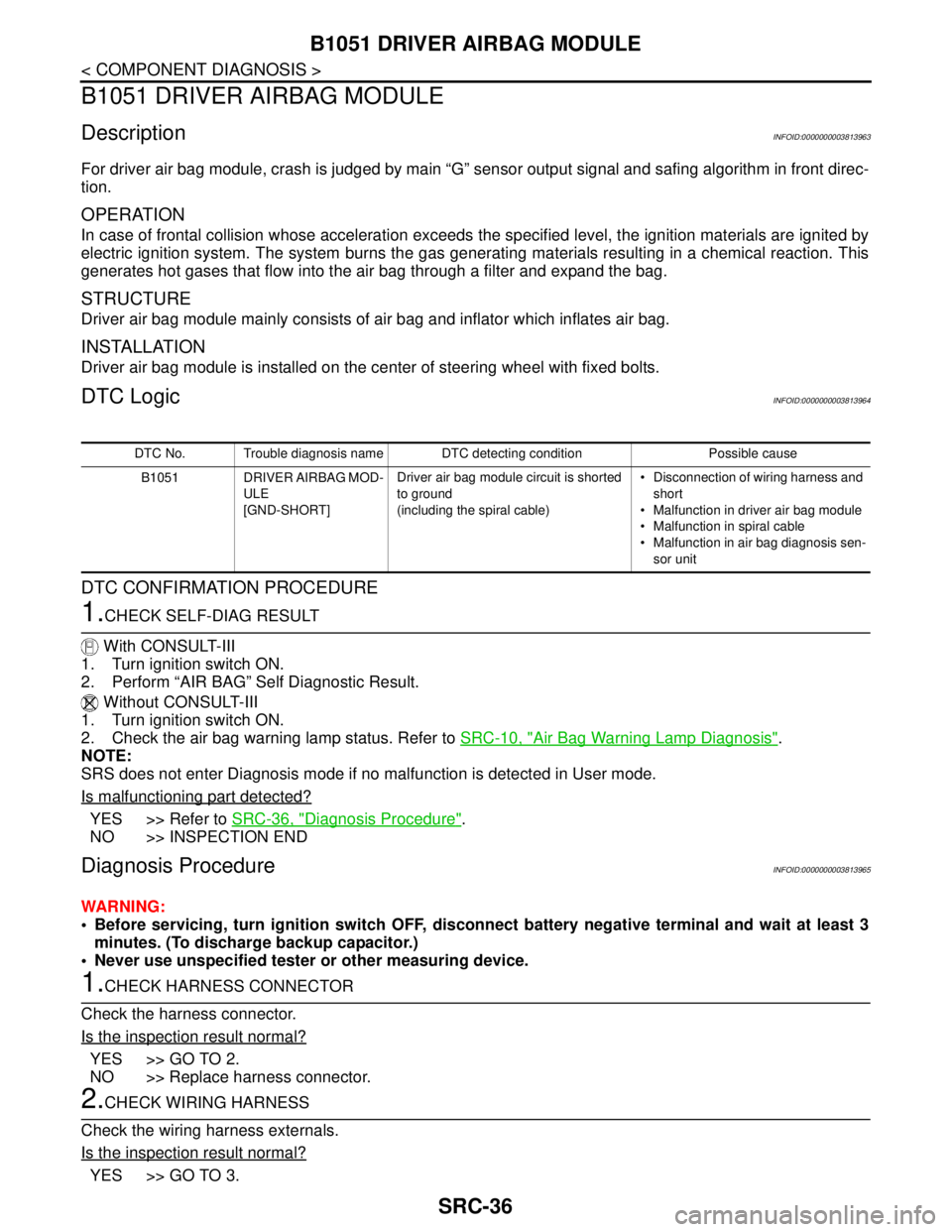
B1051 DRIVER AIRBAG MODULE
B1051 DRIVER AIRBAG MODULE
DescriptionINFOID:0000000003813963
For driver air bag module, crash is judged by main “G” sensor output signal and safing algorithm in front direc-
tion.
OPERATION
In case of frontal collision whose acceleration exceeds the specified level, the ignition materials are ignited by
electric ignition system. The system burns the gas generating materials resulting in a chemical reaction. This
generates hot gases that flow into the air bag through a filter and expand the bag.
STRUCTURE
Driver air bag module mainly consists of air bag and inflator which inflates air bag.
INSTALLATION
Driver air bag module is installed on the center of steering wheel with fixed bolts.
DTC LogicINFOID:0000000003813964
DTC CONFIRMATION PROCEDURE
1.CHECK SELF-DIAG RESULT
With CONSULT-III
1. Turn ignition switch ON.
2. Perform “AIR BAG” Self Diagnostic Result.
Without CONSULT-III
1. Turn ignition switch ON.
2. Check the air bag warning lamp status. Refer to SRC-10, "
Air Bag Warning Lamp Diagnosis".
NOTE:
SRS does not enter Diagnosis mode if no malfunction is detected in User mode.
Is malfunctioning part detected?
YES >> Refer to SRC-36, "Diagnosis Procedure".
NO >> INSPECTION END
Diagnosis ProcedureINFOID:0000000003813965
WARNING:
Before servicing, turn ignition switch OFF, disconnect battery negative terminal and wait at least 3
minutes. (To discharge backup capacitor.)
Never use unspecified tester or other measuring device.
1.CHECK HARNESS CONNECTOR
Check the harness connector.
Is the inspection result normal?
YES >> GO TO 2.
NO >> Replace harness connector.
2.CHECK WIRING HARNESS
Check the wiring harness externals.
Is the inspection result normal?
YES >> GO TO 3.
DTC No. Trouble diagnosis name DTC detecting condition Possible cause
B1051 DRIVER AIRBAG MOD-
ULE
[GND-SHORT]Driver air bag module circuit is shorted
to ground
(including the spiral cable) Disconnection of wiring harness and
short
Malfunction in driver air bag module
Malfunction in spiral cable
Malfunction in air bag diagnosis sen-
sor unit
Page 4281 of 5121

SRC-38
< COMPONENT DIAGNOSIS >
B1052 DRIVER AIRBAG MODULE
B1052 DRIVER AIRBAG MODULE
DescriptionINFOID:0000000003813966
For driver air bag module, crash is judged by main “G” sensor output signal and safing algorithm in front direc-
tion.
OPERATION
In case of frontal collision whose acceleration exceeds the specified level, the ignition materials are ignited by
electric ignition system. The system burns the gas generating materials resulting in a chemical reaction. This
generates hot gases that flow into the air bag through a filter and expand the bag.
STRUCTURE
Driver air bag module mainly consists of air bag and inflator which inflates air bag.
INSTALLATION
Driver air bag module is installed on the center of steering wheel with fixed bolts.
DTC LogicINFOID:0000000003813967
DTC CONFIRMATION PROCEDURE
1.CHECK SELF-DIAG RESULT
With CONSULT-III
1. Turn ignition switch ON.
2. Perform “AIR BAG” Self Diagnostic Result.
Without CONSULT-III
1. Turn ignition switch ON.
2. Check the air bag warning lamp status. Refer to SRC-10, "
Air Bag Warning Lamp Diagnosis".
NOTE:
SRS does not enter Diagnosis mode if no malfunction is detected in User mode.
Is malfunctioning part detected?
YES >> Refer to SRC-38, "Diagnosis Procedure".
NO >> INSPECTION END
Diagnosis ProcedureINFOID:0000000003813968
WARNING:
Before servicing, turn ignition switch OFF, disconnect battery negative terminal and wait at least 3
minutes. (To discharge backup capacitor.)
Never use unspecified tester or other measuring device.
1.CHECK HARNESS CONNECTOR
Check the harness connector.
Is the inspection result normal?
YES >> GO TO 2.
NO >> Replace harness connector.
2.CHECK WIRING HARNESS
Check the wiring harness externals.
Is the inspection result normal?
YES >> GO TO 3.
DTC No. Trouble diagnosis name DTC detecting condition Possible cause
B1052 DRIVER AIRBAG MOD-
ULE
[SHORT]Driver air bag module circuit are shorted
to each other
(including the spiral cable) Disconnection of wiring harness
and short
Malfunction in driver air bag module
Malfunction in spiral cable
Malfunction in air bag diagnosis sen-
sor unit
Page 4285 of 5121
SRC-42
< COMPONENT DIAGNOSIS >
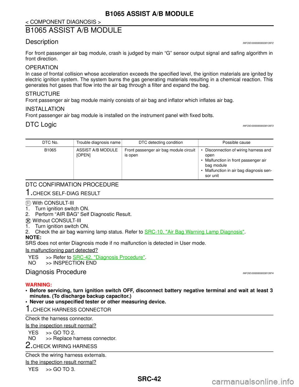
B1065 ASSIST A/B MODULE
B1065 ASSIST A/B MODULE
DescriptionINFOID:0000000003813972
For front passenger air bag module, crash is judged by main “G” sensor output signal and safing algorithm in
front direction.
OPERATION
In case of frontal collision whose acceleration exceeds the specified level, the ignition materials are ignited by
electric ignition system. The system burns the gas generating materials resulting in a chemical reaction. This
generates hot gases that flow into the air bag through a filter and expand the bag.
STRUCTURE
Front passenger air bag module mainly consists of air bag and inflator which inflates air bag.
INSTALLATION
Front passenger air bag module is installed on the instrument panel with fixed bolts.
DTC LogicINFOID:0000000003813973
DTC CONFIRMATION PROCEDURE
1.CHECK SELF-DIAG RESULT
With CONSULT-III
1. Turn ignition switch ON.
2. Perform “AIR BAG” Self Diagnostic Result.
Without CONSULT-III
1. Turn ignition switch ON.
2. Check the air bag warning lamp status. Refer to SRC-10, "
Air Bag Warning Lamp Diagnosis".
NOTE:
SRS does not enter Diagnosis mode if no malfunction is detected in User mode.
Is malfunctioning part detected?
YES >> Refer to SRC-42, "Diagnosis Procedure".
NO >> INSPECTION END
Diagnosis ProcedureINFOID:0000000003813974
WARNING:
Before servicing, turn ignition switch OFF, disconnect battery negative terminal and wait at least 3
minutes. (To discharge backup capacitor.)
Never use unspecified tester or other measuring device.
1.CHECK HARNESS CONNECTOR
Check the harness connector.
Is the inspection result normal?
YES >> GO TO 2.
NO >> Replace harness connector.
2.CHECK WIRING HARNESS
Check the wiring harness externals.
Is the inspection result normal?
YES >> GO TO 3.
DTC No. Trouble diagnosis name DTC detecting condition Possible cause
B1065 ASSIST A/B MODULE
[OPEN]Front passenger air bag module circuit
is open Disconnection of wiring harness and
open
Malfunction in front passenger air
bag module
Malfunction in air bag diagnosis sen-
sor unit
Page 4287 of 5121
SRC-44
< COMPONENT DIAGNOSIS >
B1066 ASSIST A/B MODULE
B1066 ASSIST A/B MODULE
DescriptionINFOID:0000000003813975
For front passenger air bag module, crash is judged by main “G” sensor output signal and safing algorithm in
front direction.
OPERATION
In case of frontal collision whose acceleration exceeds the specified level, the ignition materials are ignited by
electric ignition system. The system burns the gas generating materials resulting in a chemical reaction. This
generates hot gases that flow into the air bag through a filter and expand the bag.
STRUCTURE
Front passenger air bag module mainly consists of air bag and inflator which inflates air bag.
INSTALLATION
Front passenger air bag module is installed on the instrument panel with fixed bolts.
DTC LogicINFOID:0000000003813976
DTC CONFIRMATION PROCEDURE
1.CHECK SELF-DIAG RESULT
With CONSULT-III
1. Turn ignition switch ON.
2. Perform “AIR BAG” Self Diagnostic Result.
Without CONSULT-III
1. Turn ignition switch ON.
2. Check the air bag warning lamp status. Refer to SRC-10, "
Air Bag Warning Lamp Diagnosis".
NOTE:
SRS does not enter Diagnosis mode if no malfunction is detected in User mode.
Is malfunctioning part detected?
YES >> Refer to SRC-44, "Diagnosis Procedure".
NO >> INSPECTION END
Diagnosis ProcedureINFOID:0000000003813977
WARNING:
Before servicing, turn ignition switch OFF, disconnect battery negative terminal and wait at least 3
minutes. (To discharge backup capacitor.)
Never use unspecified tester or other measuring device.
1.CHECK HARNESS CONNECTOR
Check the harness connector.
Is the inspection result normal?
YES >> GO TO 2.
NO >> Replace harness connector.
2.CHECK WIRING HARNESS
Check the wiring harness externals.
Is the inspection result normal?
YES >> GO TO 3.
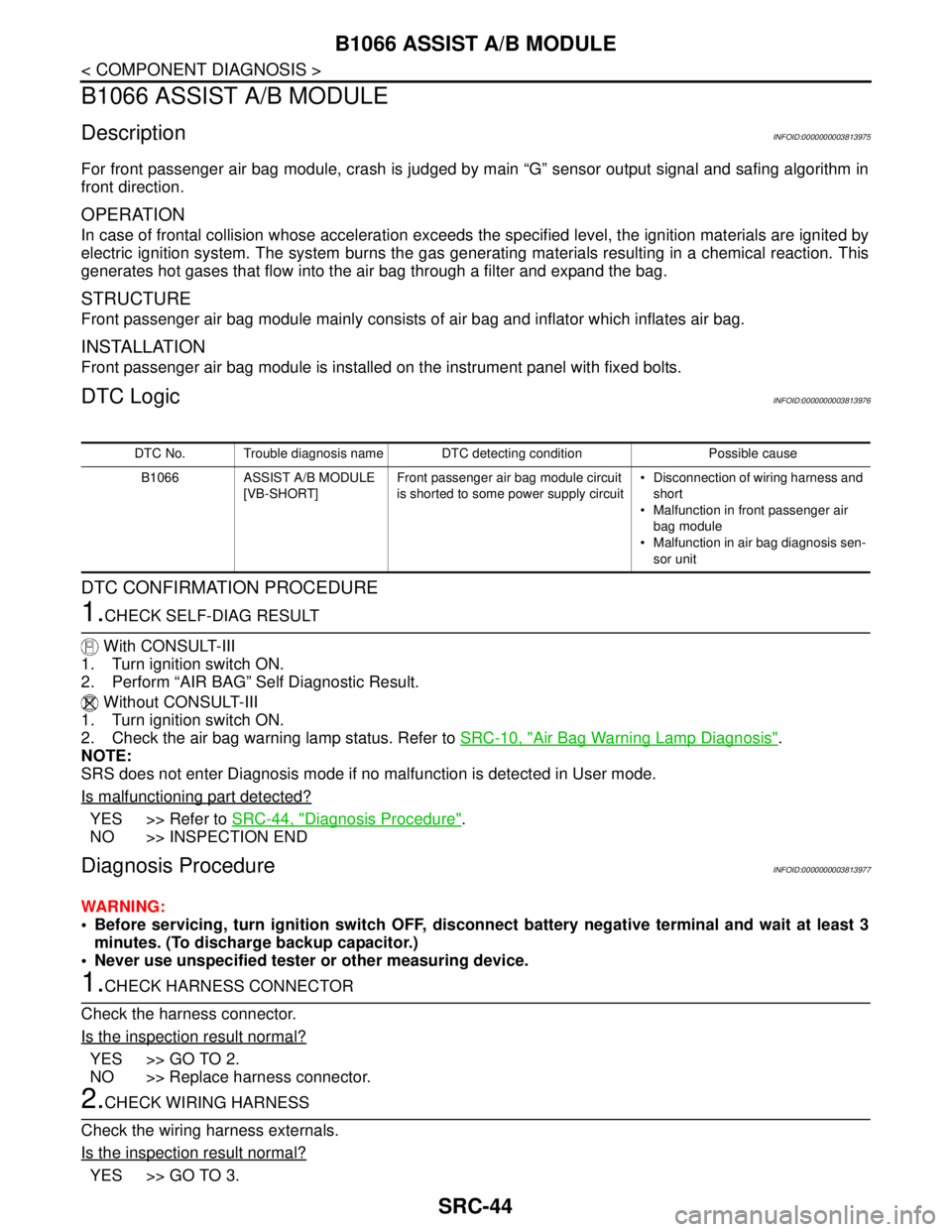
DTC No. Trouble diagnosis name DTC detecting condition Possible cause
B1066 ASSIST A/B MODULE
[VB-SHORT]Front passenger air bag module circuit
is shorted to some power supply circuit Disconnection of wiring harness and
short
Malfunction in front passenger air
bag module
Malfunction in air bag diagnosis sen-
sor unit
Page 4289 of 5121
SRC-46
< COMPONENT DIAGNOSIS >
B1067 ASSIST A/B MODULE
B1067 ASSIST A/B MODULE
DescriptionINFOID:0000000003813978
For front passenger air bag module, crash is judged by main “G” sensor output signal and safing algorithm in
front direction.
OPERATION
In case of frontal collision whose acceleration exceeds the specified level, the ignition materials are ignited by
electric ignition system. The system burns the gas generating materials resulting in a chemical reaction. This
generates hot gases that flow into the air bag through a filter and expand the bag.
STRUCTURE
Front passenger air bag module mainly consists of air bag and inflator which inflates air bag.
INSTALLATION
Front passenger air bag module is installed on the instrument panel with fixed bolts.
DTC LogicINFOID:0000000003813979
DTC CONFIRMATION PROCEDURE
1.CHECK SELF-DIAG RESULT
With CONSULT-III
1. Turn ignition switch ON.
2. Perform “AIR BAG” Self Diagnostic Result.
Without CONSULT-III
1. Turn ignition switch ON.
2. Check the air bag warning lamp status. Refer to SRC-10, "
Air Bag Warning Lamp Diagnosis".
NOTE:
SRS does not enter Diagnosis mode if no malfunction is detected in User mode.
Is malfunctioning part detected?
YES >> Refer to SRC-46, "Diagnosis Procedure".
NO >> INSPECTION END
Diagnosis ProcedureINFOID:0000000003813980
WARNING:
Before servicing, turn ignition switch OFF, disconnect battery negative terminal and wait at least 3
minutes. (To discharge backup capacitor.)
Never use unspecified tester or other measuring device.
1.CHECK HARNESS CONNECTOR
Check the harness connector.
Is the inspection result normal?
YES >> GO TO 2.
NO >> Replace harness connector.
2.CHECK WIRING HARNESS
Check the wiring harness externals.
Is the inspection result normal?
YES >> GO TO 3.
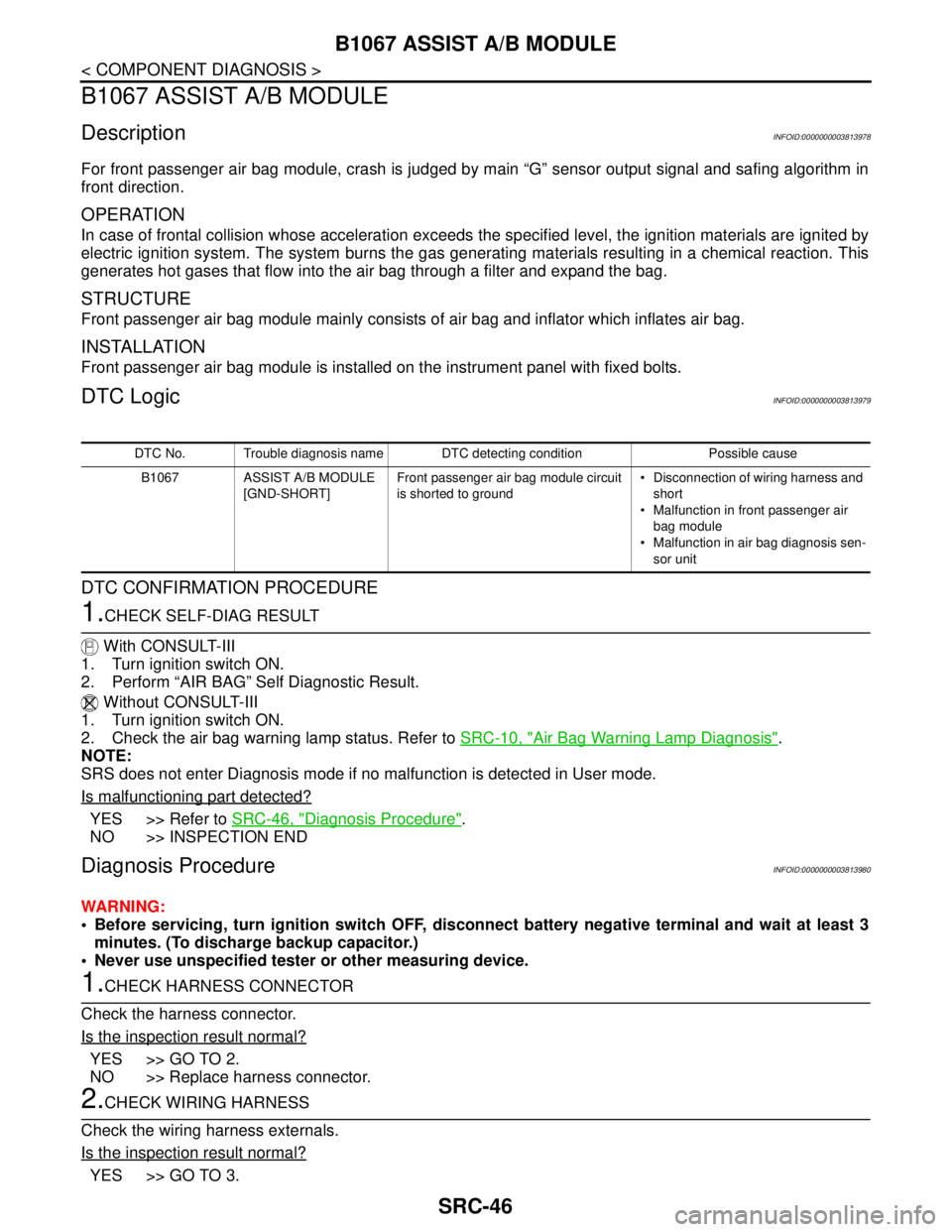
DTC No. Trouble diagnosis name DTC detecting condition Possible cause
B1067 ASSIST A/B MODULE
[GND-SHORT]Front passenger air bag module circuit
is shorted to ground Disconnection of wiring harness and
short
Malfunction in front passenger air
bag module
Malfunction in air bag diagnosis sen-
sor unit