2008 NISSAN TEANA air filter
[x] Cancel search: air filterPage 2472 of 5121

FUEL TANK
FL-9
< ON-VEHICLE REPAIR >
C
D
E
F
G
H
I
J
K
L
MA
FL
N
P O
FUEL TANK
Exploded ViewINFOID:0000000003793254
In regard to the notation of torque in the figure, (A) shows an ISO standard, (B) shows a conventional stan-
dard.
Removal and InstallationINFOID:0000000003793255
WARNING:
Be sure to read “General Precautions” when working on the fuel system. Refer to FL-2, "
General Pre-
cautions".
REMOVAL
Drain fuel from fuel tank if necessary. Refer to FL-5, "Removal and Installation".
Perform work on level place.
1. Perform steps 2 to 7 of “REMOVAL” in “FUEL LEVEL SENSOR UNIT, FUEL FILTER AND FUEL PUMP
ASSEMBLY” on fuel level sensor units. Refer to FL-5, "
Removal and Installation".
2. Remove center muffler. Refer to EX-5, "
Exploded View".
3. Remove fuel tank protector.
1. Clamp 2. Vent hose 3. Clamp
4. EVAP hose 5. Fuel tank 6. Fuel tank mounting band (RH)
7. Clip 8. Fuel tank protector 9. Fuel tank mounting band (LH)
10. Clamp 11. Fuel filler hose 12. Clamp
13. Fuel filler tube 14. Grommet 15. Fuel filler cap
A.The measurement of hexagonal
width across flats: 16 mm (0.63 in)B.The measurement of hexagonal
width across flats: 14 mm (0.55 in)
Refer to GI-4, "
Components" for symbols in the figure.
JPBIA2202GB
Page 2521 of 5121
GI-28
< PRECAUTION >
PRECAUTIONS
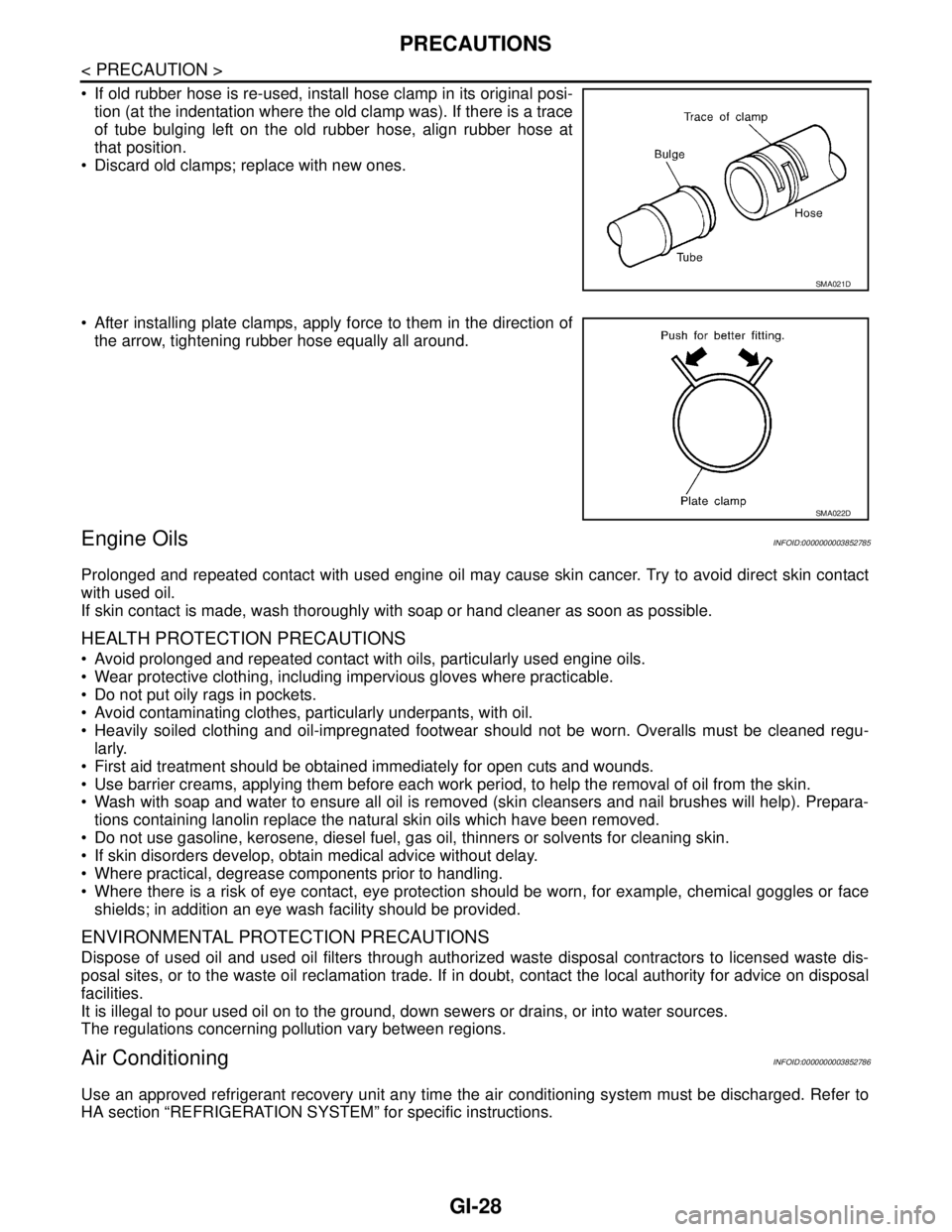
If old rubber hose is re-used, install hose clamp in its original posi-
tion (at the indentation where the old clamp was). If there is a trace
of tube bulging left on the old rubber hose, align rubber hose at
that position.
Discard old clamps; replace with new ones.
After installing plate clamps, apply force to them in the direction of
the arrow, tightening rubber hose equally all around.
Engine OilsINFOID:0000000003852785
Prolonged and repeated contact with used engine oil may cause skin cancer. Try to avoid direct skin contact
with used oil.
If skin contact is made, wash thoroughly with soap or hand cleaner as soon as possible.
HEALTH PROTECTION PRECAUTIONS
Avoid prolonged and repeated contact with oils, particularly used engine oils.
Wear protective clothing, including impervious gloves where practicable.
Do not put oily rags in pockets.
Avoid contaminating clothes, particularly underpants, with oil.
Heavily soiled clothing and oil-impregnated footwear should not be worn. Overalls must be cleaned regu-
larly.
First aid treatment should be obtained immediately for open cuts and wounds.
Use barrier creams, applying them before each work period, to help the removal of oil from the skin.
Wash with soap and water to ensure all oil is removed (skin cleansers and nail brushes will help). Prepara-
tions containing lanolin replace the natural skin oils which have been removed.
Do not use gasoline, kerosene, diesel fuel, gas oil, thinners or solvents for cleaning skin.
If skin disorders develop, obtain medical advice without delay.
Where practical, degrease components prior to handling.
Where there is a risk of eye contact, eye protection should be worn, for example, chemical goggles or face
shields; in addition an eye wash facility should be provided.
ENVIRONMENTAL PROTECTION PRECAUTIONS
Dispose of used oil and used oil filters through authorized waste disposal contractors to licensed waste dis-
posal sites, or to the waste oil reclamation trade. If in doubt, contact the local authority for advice on disposal
facilities.
It is illegal to pour used oil on to the ground, down sewers or drains, or into water sources.
The regulations concerning pollution vary between regions.
Air ConditioningINFOID:0000000003852786
Use an approved refrigerant recovery unit any time the air conditioning system must be discharged. Refer to
HA section “REFRIGERATION SYSTEM” for specific instructions.
SMA021D
SMA022D
Page 2621 of 5121
HA-52
< ON-VEHICLE REPAIR >
EVAPORATOR
EVAPORATOR
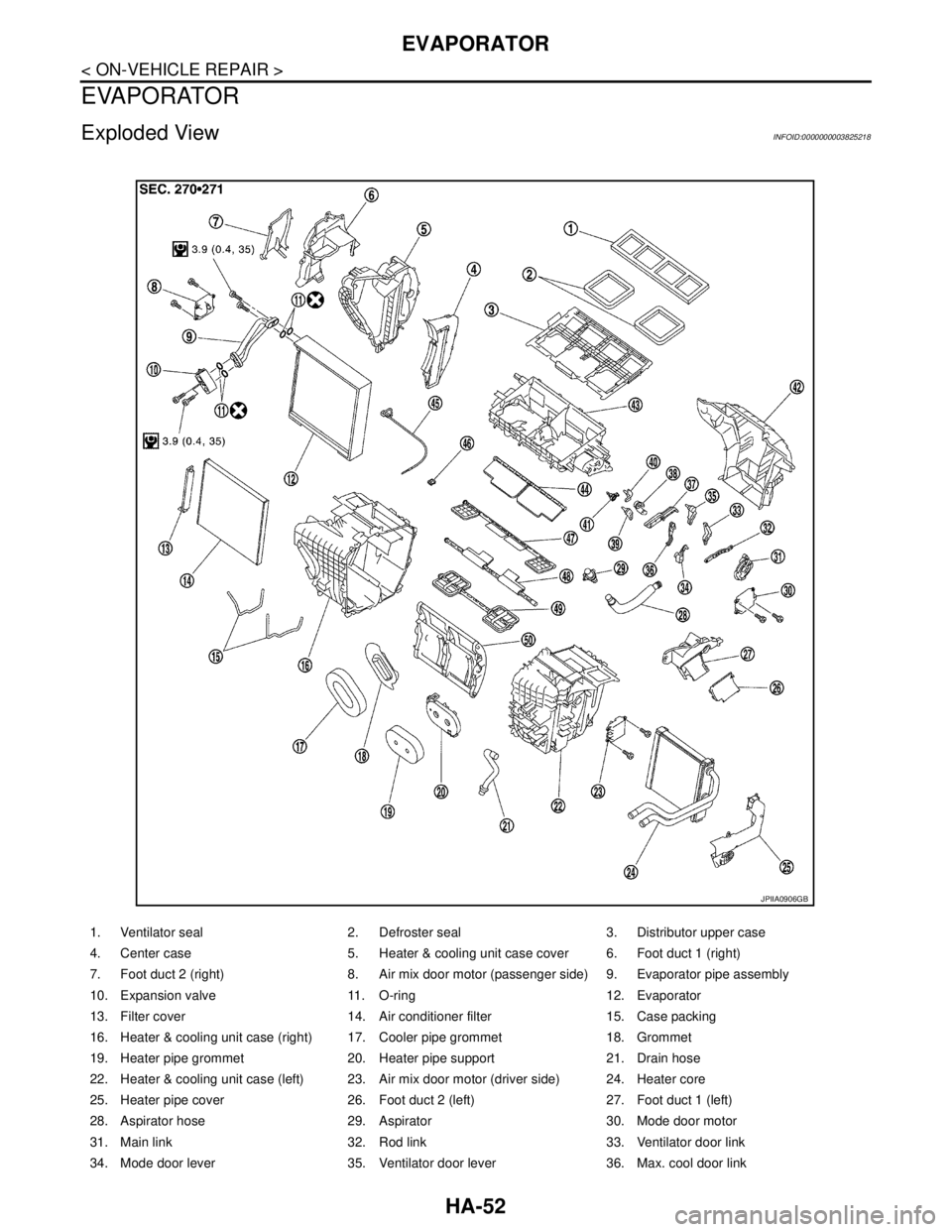
Exploded ViewINFOID:0000000003825218
1. Ventilator seal 2. Defroster seal 3. Distributor upper case
4. Center case 5. Heater & cooling unit case cover 6. Foot duct 1 (right)
7. Foot duct 2 (right) 8. Air mix door motor (passenger side) 9. Evaporator pipe assembly
10. Expansion valve 11. O-ring 12. Evaporator
13. Filter cover 14. Air conditioner filter 15. Case packing
16. Heater & cooling unit case (right) 17. Cooler pipe grommet 18. Grommet
19. Heater pipe grommet 20. Heater pipe support 21. Drain hose
22. Heater & cooling unit case (left) 23. Air mix door motor (driver side) 24. Heater core
25. Heater pipe cover 26. Foot duct 2 (left) 27. Foot duct 1 (left)
28. Aspirator hose 29. Aspirator 30. Mode door motor
31. Main link 32. Rod link 33. Ventilator door link
34. Mode door lever 35. Ventilator door lever 36. Max. cool door link
JPIIA0906GB
Page 2623 of 5121
HA-54
< ON-VEHICLE REPAIR >
EVAPORATOR PIPE ASSEMBLY
EVAPORATOR PIPE ASSEMBLY
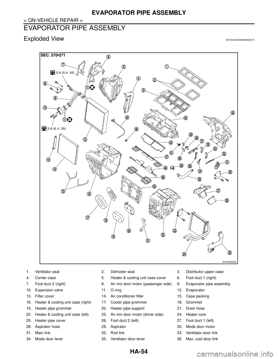
Exploded ViewINFOID:0000000003825219
1. Ventilator seal 2. Defroster seal 3. Distributor upper case
4. Center case 5. Heater & cooling unit case cover 6. Foot duct 1 (right)
7. Foot duct 2 (right) 8. Air mix door motor (passenger side) 9. Evaporator pipe assembly
10. Expansion valve 11. O-ring 12. Evaporator
13. Filter cover 14. Air conditioner filter 15. Case packing
16. Heater & cooling unit case (right) 17. Cooler pipe grommet 18. Grommet
19. Heater pipe grommet 20. Heater pipe support 21. Drain hose
22. Heater & cooling unit case (left) 23. Air mix door motor (driver side) 24. Heater core
25. Heater pipe cover 26. Foot duct 2 (left) 27. Foot duct 1 (left)
28. Aspirator hose 29. Aspirator 30. Mode door motor
31. Main link 32. Rod link 33. Ventilator door link
34. Mode door lever 35. Ventilator door lever 36. Max. cool door link
JPIIA0906GB
Page 2626 of 5121
EXPANSION VALVE
HA-57
< ON-VEHICLE REPAIR >
C
D
E
F
G
H
J
K
L
MA
B
HA
N
O
P
EXPANSION VALVE
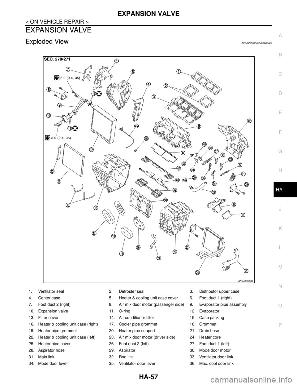
Exploded ViewINFOID:0000000003825220
1. Ventilator seal 2. Defroster seal 3. Distributor upper case
4. Center case 5. Heater & cooling unit case cover 6. Foot duct 1 (right)
7. Foot duct 2 (right) 8. Air mix door motor (passenger side) 9. Evaporator pipe assembly
10. Expansion valve 11. O-ring 12. Evaporator
13. Filter cover 14. Air conditioner filter 15. Case packing
16. Heater & cooling unit case (right) 17. Cooler pipe grommet 18. Grommet
19. Heater pipe grommet 20. Heater pipe support 21. Drain hose
22. Heater & cooling unit case (left) 23. Air mix door motor (driver side) 24. Heater core
25. Heater pipe cover 26. Foot duct 2 (left) 27. Foot duct 1 (left)
28. Aspirator hose 29. Aspirator 30. Mode door motor
31. Main link 32. Rod link 33. Ventilator door link
34. Mode door lever 35. Ventilator door lever 36. Max. cool door link
JPIIA0906GB
Page 2803 of 5121
![NISSAN TEANA 2008 Service Manual B262A, B262B, B2657, B2658 GAS SENSOR
HAC-175
< COMPONENT DIAGNOSIS >[WITH 7 INCH DISPLAY]
C
D
E
F
G
H
J
K
L
MA
B
HAC
N
O
P
B262A, B262B, B2657, B2658 GAS SENSOR
WITH INTELLIGENT AIR CONDITIONER SYSTE NISSAN TEANA 2008 Service Manual B262A, B262B, B2657, B2658 GAS SENSOR
HAC-175
< COMPONENT DIAGNOSIS >[WITH 7 INCH DISPLAY]
C
D
E
F
G
H
J
K
L
MA
B
HAC
N
O
P
B262A, B262B, B2657, B2658 GAS SENSOR
WITH INTELLIGENT AIR CONDITIONER SYSTE](/manual-img/5/57391/w960_57391-2802.png)
B262A, B262B, B2657, B2658 GAS SENSOR
HAC-175
< COMPONENT DIAGNOSIS >[WITH 7 INCH DISPLAY]
C
D
E
F
G
H
J
K
L
MA
B
HAC
N
O
P
B262A, B262B, B2657, B2658 GAS SENSOR
WITH INTELLIGENT AIR CONDITIONER SYSTEM
WITH INTELLIGENT AIR CONDITIONER SYSTEM : DescriptionINFOID:0000000003884752
COMPONENT DESCRIPTION
Gas Sensor
The gas sensor (1) is attached on the bumper upper retainer. It
detects smell of exhaust gas and converts it into a duty ratio which is
then input into the A/C auto amp.
Gas Sensor Circuit
SMELL OF EXHAUST GAS INPUT PROCESS
Gas sensor detects ambient atmospheric CO and NO2, and converts them to values of resistance. The values
are converted to signals with the gas sensor internal circuit, then auto amp. inputs the signals.
Gas sensor has a construction that detects CO and NO
2 by gas sensor element from the air intake of the case
through a filter (waterproof sheet). It sends output signals to auto amp. in response to a resistance value con-
version by gas sensor elements. Output signals prevent a smell of exhaust gas from getting into vehicle by
performing corrections according to various driving conditions.
WITH INTELLIGENT AIR CONDITIONER SYSTEM : DTC LogicINFOID:0000000003884753
DTC DETECTION LOGIC
JPIIA0900ZZ
JPIIA1009GB
PJIA0049E
Page 3173 of 5121

LU-1
ENGINE
C
DE
F
G H
I
J
K L
M
SECTION LU
A
LU
N
O P
CONTENTS
ENGINE LUBRICATION SYSTEM
FUNCTION DIAGNOSIS .. .............................2
DESCRIPTION ............................................... .....2
Engine Lubrication System ................................ ......2
Engine Lubrication System Schematic ......................3
PRECAUTION ...............................................4
PRECAUTIONS .............................................. .....4
Precaution for Liquid Gasket ............................... ......4
PREPARATION ............................................5
PREPARATION .............................................. .....5
Special Service Tool ........................................... ......5
Commercial Service Tool ..........................................5
ON-VEHICLE MAINTENANCE .....................7
ENGINE OIL ................................................... .....7
Inspection ............................................................ ......7
Draining .....................................................................8
Refilling .....................................................................9
OIL FILTER ........................................................10
Removal and Installation ..................................... ....10
Inspection ................................................................10
ON-VEHICLE REPAIR .................................11
OIL COOLER ....................................................11
Exploded View ..................................................... ....11
Removal and Installation .........................................11
Inspection ................................................................12
DISASSEMBLY AND ASSEMBLY ..............13
OIL PUMP .........................................................13
Exploded View ..................................................... ....13
Removal and Installation .........................................13
Disassembly and Assembly .....................................13
Inspection ................................................................14
SERVICE DATA AND SPECIFICATIONS
(SDS) ............... .............................................
16
SERVICE DATA AND SPECIFICATIONS
(SDS) .................................................................
16
Periodical Maintenance Specification ................ ....16
Engine Oil Pressure ...............................................16
Oil Pump .................................................................16
Regulator Valve ......................................................16
Page 3179 of 5121
ENGINE OIL
LU-7
< ON-VEHICLE MAINTENANCE >
C
D
E
F
G
H
I
J
K
L
MA
LU
N
P O
ON-VEHICLE MAINTENANCE
ENGINE OIL
InspectionINFOID:0000000003793121
ENGINE OIL LEVEL
NOTE:
Before starting engine, put vehicle horizontally and check the engine oil level. If engine is already started, stop
it and allow 10 minutes before checking.
1. Pull out oil level gauge and wipe it clean.
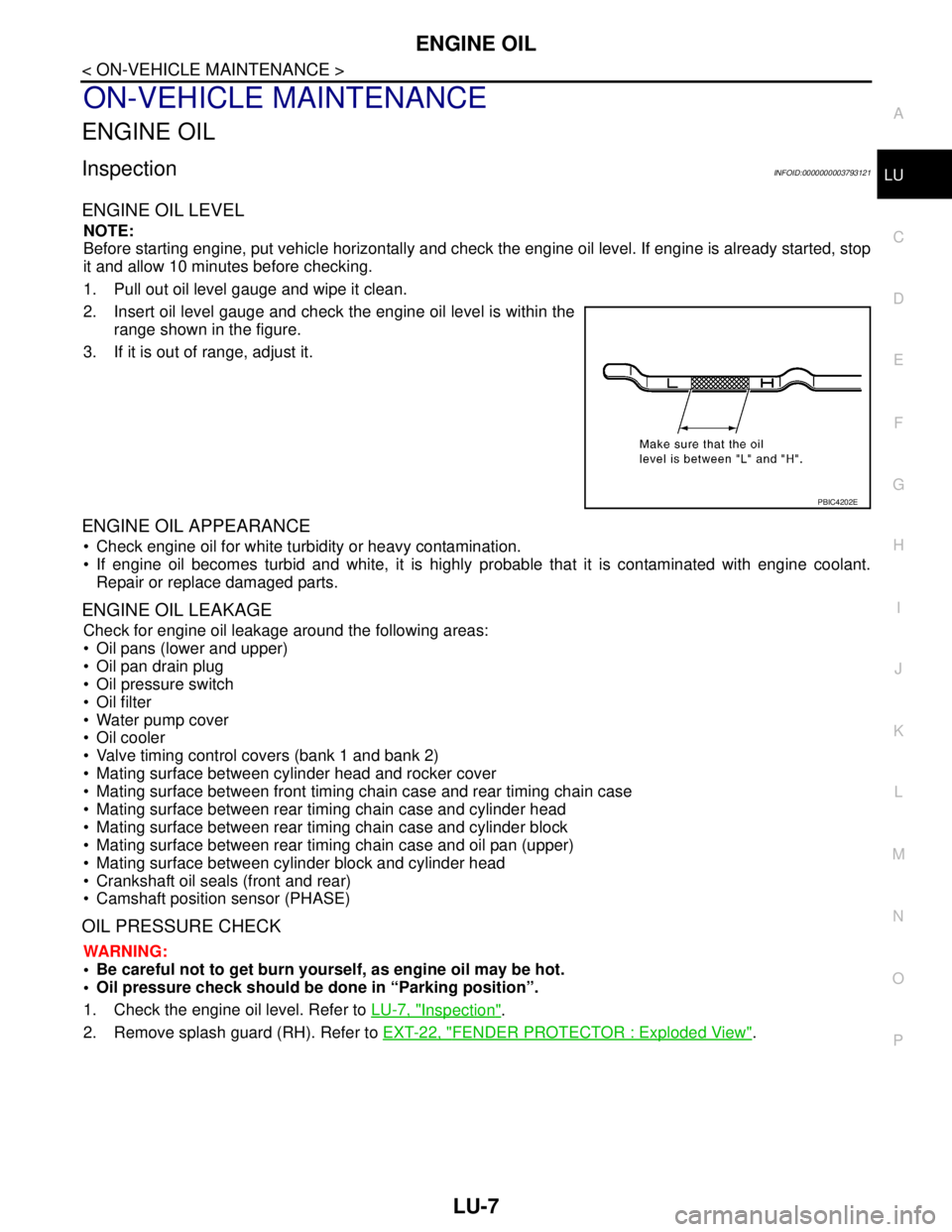
2. Insert oil level gauge and check the engine oil level is within the
range shown in the figure.
3. If it is out of range, adjust it.
ENGINE OIL APPEARANCE
Check engine oil for white turbidity or heavy contamination.
If engine oil becomes turbid and white, it is highly probable that it is contaminated with engine coolant.
Repair or replace damaged parts.
ENGINE OIL LEAKAGE
Check for engine oil leakage around the following areas:
Oil pans (lower and upper)
Oil pan drain plug
Oil pressure switch
Oil filter
Water pump cover
Oil cooler
Valve timing control covers (bank 1 and bank 2)
Mating surface between cylinder head and rocker cover
Mating surface between front timing chain case and rear timing chain case
Mating surface between rear timing chain case and cylinder head
Mating surface between rear timing chain case and cylinder block
Mating surface between rear timing chain case and oil pan (upper)
Mating surface between cylinder block and cylinder head
Crankshaft oil seals (front and rear)
Camshaft position sensor (PHASE)
OIL PRESSURE CHECK
WARNING:
• Be careful not to get burn yourself, as engine oil may be hot.
Oil pressure check should be done in “Parking position”.
1. Check the engine oil level. Refer to LU-7, "
Inspection".
2. Remove splash guard (RH). Refer to EXT-22, "
FENDER PROTECTOR : Exploded View".
PBIC4202E