2008 NISSAN TEANA engine
[x] Cancel search: enginePage 1879 of 5121
EM-4
< SYMPTOM DIAGNOSIS >
NOISE, VIBRATION AND HARSHNESS (NVH) TROUBLESHOOTING
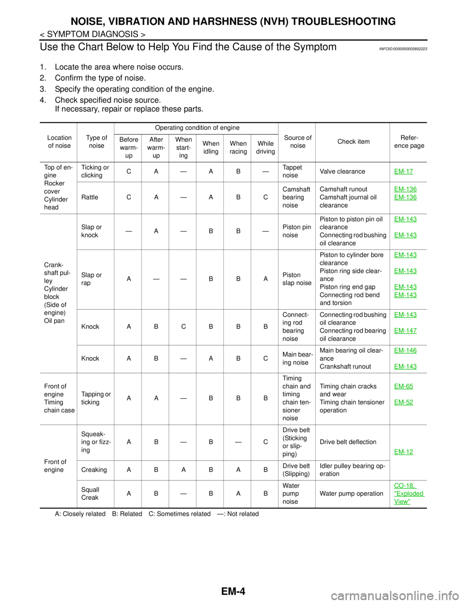
Use the Chart Below to Help You Find the Cause of the Symptom
INFOID:0000000003802223
1. Locate the area where noise occurs.
2. Confirm the type of noise.
3. Specify the operating condition of the engine.
4. Check specified noise source.
If necessary, repair or replace these parts.
A: Closely related B: Related C: Sometimes related —: Not related Location
of noiseType of
noiseOperating condition of engine
Source of
noiseCheck itemRefer-
ence page Before
warm-
upAfter
warm-
upWhen
start-
ingWhen
idlingWhen
racingWhile
driving
Top of en-
gine
Rocker
cover
Cylinder
headTicking or
clickingCA—AB—Tappet
noiseValve clearanceEM-17
Rattle C A — A B CCamshaft
bearing
noiseCamshaft runout
Camshaft journal oil
clearanceEM-136EM-136
Crank-
shaft pul-
ley
Cylinder
block
(Side of
engine)
Oil panSlap or
knock—A—B B—Piston pin
noisePiston to piston pin oil
clearance
Connecting rod bushing
oil clearanceEM-143
EM-143
Slap or
rapA——B B APiston
slap noisePiston to cylinder bore
clearance
Piston ring side clear-
ance
Piston ring end gap
Connecting rod bend
and torsionEM-143EM-143
EM-143
EM-143
Knock A B C B B BConnect-
ing rod
bearing
noiseConnecting rod bushing
oil clearance
Connecting rod bearing
oil clearanceEM-143EM-147
Knock A B — A B CMain bear-
ing noiseMain bearing oil clear-
ance
Crankshaft runoutEM-146
EM-143
Front of
engine
Timing
chain caseTapping or
tickingAA—BBBTiming
chain and
timing
chain ten-
sioner
noiseTiming chain cracks
and wear
Timing chain tensioner
operationEM-65
EM-52
Front of
engineSqueak-
ing or fizz-
ingAB—B—CDrive belt
(Sticking
or slip-
ping)Drive belt deflection
EM-12
CreakingABABABDrive belt
(Slipping)Idler pulley bearing op-
eration
Squall
CreakAB—BABWater
pump
noiseWater pump operationCO-18,
"Exploded
View"
Page 1881 of 5121

EM-6
< PRECAUTION >
PRECAUTIONS
3. Disconnect both battery cables. The steering lock will remain released with both battery cables discon-
nected and the steering wheel can be turned.
4. Perform the necessary repair operation.
5. When the repair work is completed, re-connect both battery cables. With the brake pedal released, turn
the push-button ignition switch from ACC position to ON position, then to LOCK position. (The steering
wheel will lock when the push-button ignition switch is turned to LOCK position.)
6. Perform self-diagnosis check of all control units using CONSULT-III.
Precaution for Drain Engine Coolant and Engine OilINFOID:0000000003802227
Drain engine coolant and engine oil when the engine is cooled.
Precaution for Disconnecting Fuel PipingINFOID:0000000003802228
Before starting work, check no fire or spark producing items are in the work area.
Release fuel pressure before disconnecting and disassembly.
After disconnecting pipes, plug openings to stop fuel leakage.
Precaution for Removal and DisassemblyINFOID:0000000003802229
When instructed to use SST, use the specified tools. Always be careful to work safely, avoid forceful or unin-
structed operations.
Exercise maximum care to avoid damage to mating or sliding surfaces.
Dowel pins are used for several parts alignment. When replacing and reassembling parts with dowel pins,
check that dowel pins are installed in the original position.
Cover openings of engine system with a tape or the equivalent, if necessary, to seal out foreign materials.
Mark and arrange disassembly parts in an organized way for easy troubleshooting and reassembly.
When loosening nuts and bolts, as a basic rule, start with the one furthest outside, then the one diagonally
opposite, and so on. If the order of loosening is specified, do exactly as specified. Power tools may be used
in the step.
Precaution for Inspection, Repair and ReplacementINFOID:0000000003802230
Before repairing or replacing, thoroughly inspect parts. Inspect new replacement parts in the same way, and
replace if necessary.
Precaution for Assembly and InstallationINFOID:0000000003802231
Use torque wrench to tighten bolts or nuts to specification.
When tightening nuts and bolts, as a basic rule, equally tighten in several different steps starting with the
ones in center, then ones on inside and outside diagonally in this order. If the order of tightening is specified,
do exactly as specified.
Replace with new gasket, packing, oil seal or O-ring.
Dowel pins are used for several parts alignment. When replacing and reassembling parts with dowel pins,
check that dowel pins are installed in the original position.
Thoroughly wash, clean, and air-blow each part. Carefully check engine oil or engine coolant passages for
any restriction and blockage.
Avoid damaging sliding or mating surfaces. Completely remove foreign materials such as cloth lint or dust.
Before assembly, oil sliding surfaces well.
Release air within route when refilling after draining engine coolant.
After repairing, start the engine and increase engine speed to check engine coolant, fuel, engine oil, and
exhaust gases for leakage.
Precaution for Angle TighteningINFOID:0000000003802232
Use the angle wrench [SST: KV10112100 (BT8653-A)] for the final tightening of the following engine parts:
- Cylinder head bolts
- Main bearing cap bolts
- Connecting rod cap bolts
- Crankshaft pulley bolt (No the angle wrench is required as bolt flange is provided with notches for angle
tightening)
Never use a torque value for final tightening.
The torque value for these parts are for a preliminary step.
Page 1882 of 5121
PRECAUTIONS
EM-7
< PRECAUTION >
C
D
E
F
G
H
I
J
K
L
MA
EM
N
P O
Ensure thread and seat surfaces are clean and coated with engine oil.
Precaution for Liquid GasketINFOID:0000000003802233
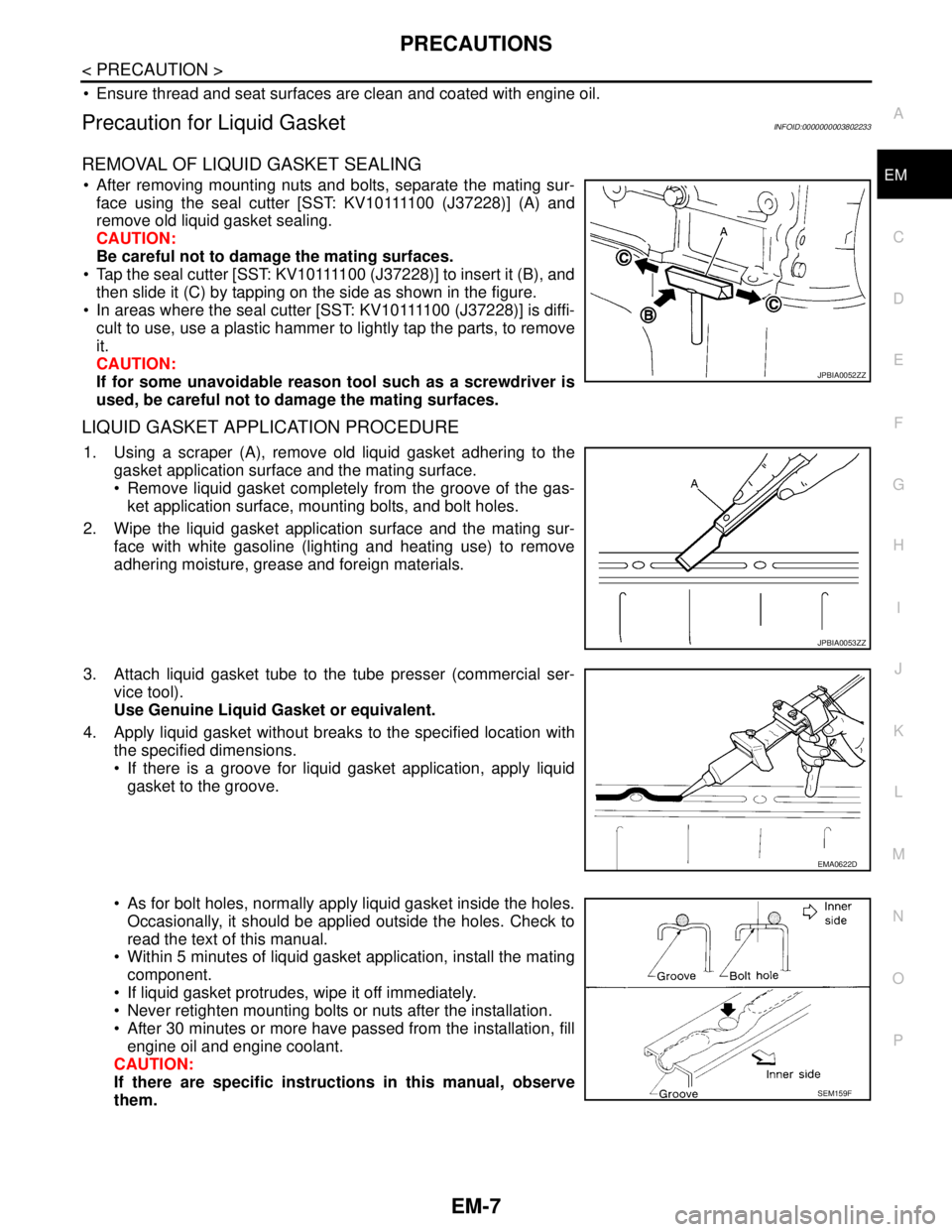
REMOVAL OF LIQUID GASKET SEALING
After removing mounting nuts and bolts, separate the mating sur-
f a c e u s i n g t h e s e a l c u t t e r [ S S T: K V 1 0 1111 0 0 ( J37228)] (A) and
remove old liquid gasket sealing.
CAUTION:
Be careful not to damage the mating surfaces.
Tap the seal cutter [SST: KV10111100 (J37228)] to insert it (B), and
then slide it (C) by tapping on the side as shown in the figure.
In areas where the seal cutter [SST: KV10111100 (J37228)] is diffi-
cult to use, use a plastic hammer to lightly tap the parts, to remove
it.
CAUTION:
If for some unavoidable reason tool such as a screwdriver is
used, be careful not to damage the mating surfaces.
LIQUID GASKET APPLICATION PROCEDURE
1. Using a scraper (A), remove old liquid gasket adhering to the
gasket application surface and the mating surface.
Remove liquid gasket completely from the groove of the gas-
ket application surface, mounting bolts, and bolt holes.
2. Wipe the liquid gasket application surface and the mating sur-
face with white gasoline (lighting and heating use) to remove
adhering moisture, grease and foreign materials.
3. Attach liquid gasket tube to the tube presser (commercial ser-
vice tool).
Use Genuine Liquid Gasket or equivalent.
4. Apply liquid gasket without breaks to the specified location with
the specified dimensions.
If there is a groove for liquid gasket application, apply liquid
gasket to the groove.
As for bolt holes, normally apply liquid gasket inside the holes.
Occasionally, it should be applied outside the holes. Check to
read the text of this manual.
Within 5 minutes of liquid gasket application, install the mating
component.
If liquid gasket protrudes, wipe it off immediately.
Never retighten mounting bolts or nuts after the installation.
After 30 minutes or more have passed from the installation, fill
engine oil and engine coolant.
CAUTION:
If there are specific instructions in this manual, observe
them.
JPBIA0052ZZ
JPBIA0053ZZ
EMA0622D
SEM159F
Page 1885 of 5121

EM-10
< PREPARATION >
PREPARATION
(—)
Manual lift table caddyRemoving and installing engine
(J24239-01)
Cylinder head bolt wrenchLoosening and tightening cylinder head bolt,
and used with the angle wrench [SST:
KV10112100 (BT8653-A)]
a: 13 mm (0.51 in) dia.
b: 12 mm (0.47 in)
c: 10 mm (0.39 in)
(—)
1.Compression tester
2.AdapterChecking compression pressure
(—)
Spark plug wrenchRemoving and installing spark plug
a: 14 mm (0.55 in)
(—)
Pulley holderRemoving and installing crankshaft pulley
(—)
Valve seat cutter setFinishing valve seat dimensions
(—)
Piston ring expanderRemoving and installing piston ring (SPX North America No.)
Tool nameDescription
ZZA1210D
NT583
ZZA0008D
JPBIA0399ZZ
ZZA1010D
NT048
NT030
Page 1887 of 5121
EM-12
< ON-VEHICLE MAINTENANCE >
DRIVE BELT
ON-VEHICLE MAINTENANCE
DRIVE BELT
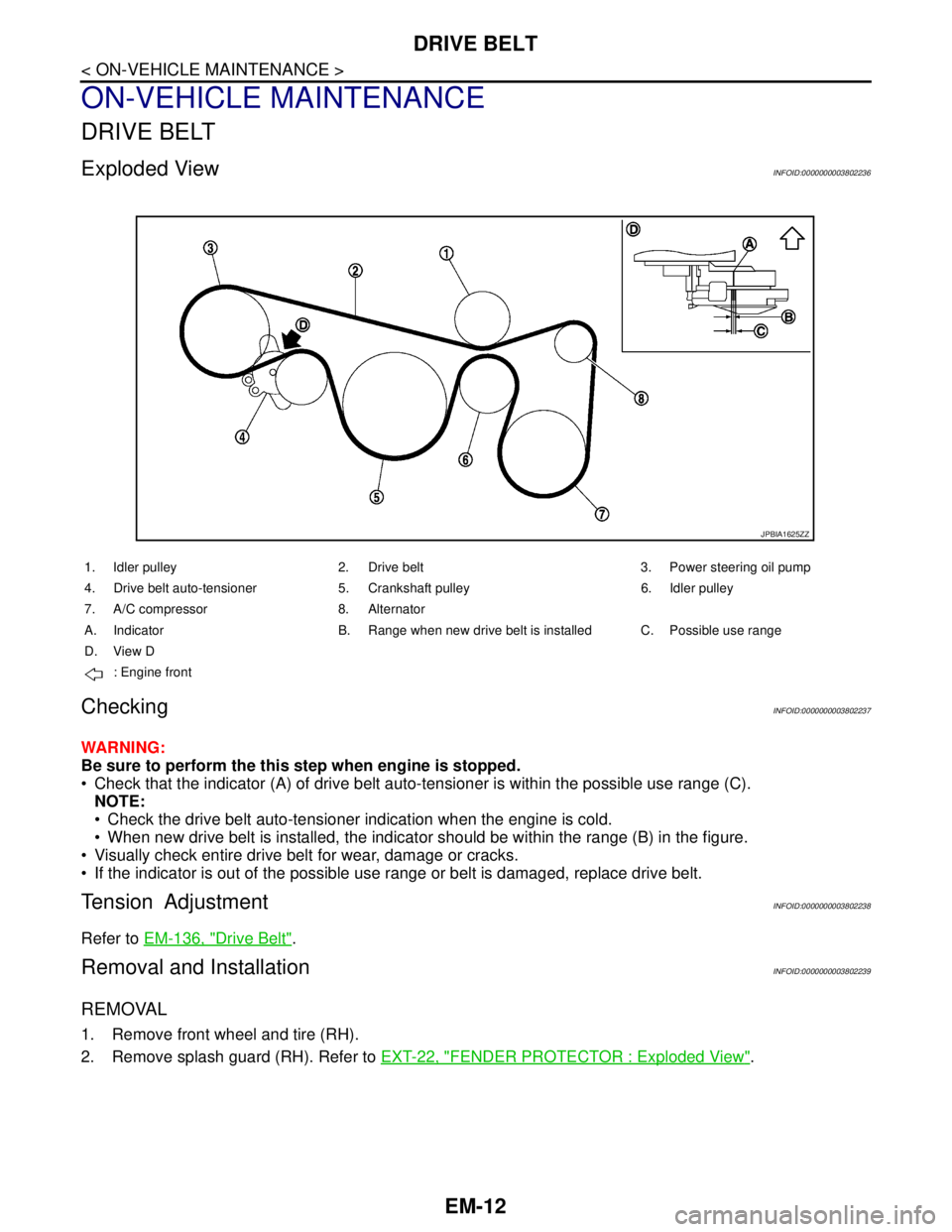
Exploded ViewINFOID:0000000003802236
CheckingINFOID:0000000003802237
WARNING:
Be sure to perform the this step when engine is stopped.
Check that the indicator (A) of drive belt auto-tensioner is within the possible use range (C).
NOTE:
Check the drive belt auto-tensioner indication when the engine is cold.
When new drive belt is installed, the indicator should be within the range (B) in the figure.
Visually check entire drive belt for wear, damage or cracks.
If the indicator is out of the possible use range or belt is damaged, replace drive belt.
Tension AdjustmentINFOID:0000000003802238
Refer to EM-136, "Drive Belt".
Removal and InstallationINFOID:0000000003802239
REMOVAL
1. Remove front wheel and tire (RH).
2. Remove splash guard (RH). Refer to EXT-22, "
FENDER PROTECTOR : Exploded View".
JPBIA1625ZZ
1. Idler pulley 2. Drive belt 3. Power steering oil pump
4. Drive belt auto-tensioner 5. Crankshaft pulley 6. Idler pulley
7. A/C compressor 8. Alternator
A. Indicator B. Range when new drive belt is installed C. Possible use range
D. View D
: Engine front
Page 1888 of 5121
DRIVE BELT
EM-13
< ON-VEHICLE MAINTENANCE >
C
D
E
F
G
H
I
J
K
L
MA
EM
N
P O
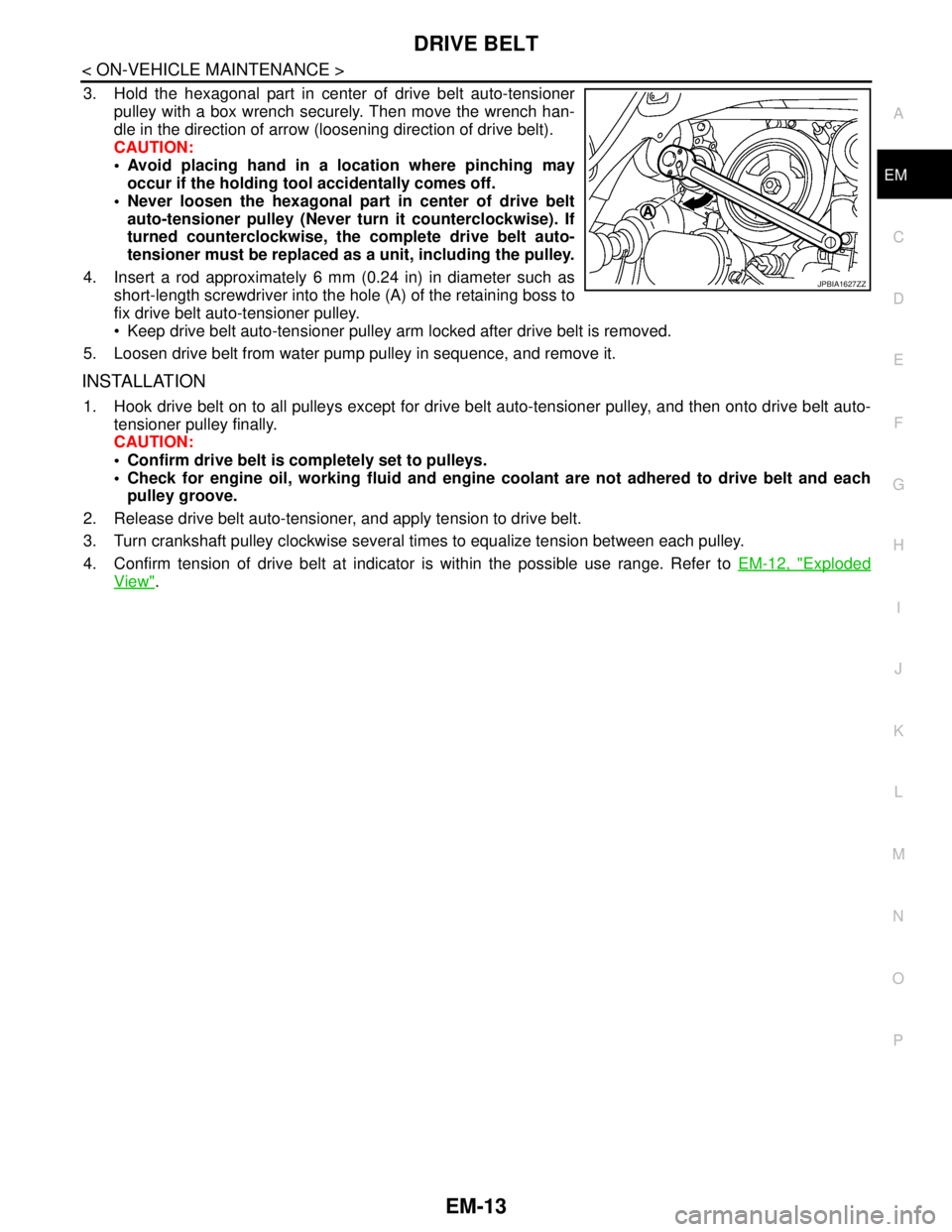
3. Hold the hexagonal part in center of drive belt auto-tensioner
pulley with a box wrench securely. Then move the wrench han-
dle in the direction of arrow (loosening direction of drive belt).
CAUTION:
Avoid placing hand in a location where pinching may
occur if the holding tool accidentally comes off.
Never loosen the hexagonal part in center of drive belt
auto-tensioner pulley (Never turn it counterclockwise). If
turned counterclockwise, the complete drive belt auto-
tensioner must be replaced as a unit, including the pulley.
4. Insert a rod approximately 6 mm (0.24 in) in diameter such as
short-length screwdriver into the hole (A) of the retaining boss to
fix drive belt auto-tensioner pulley.
Keep drive belt auto-tensioner pulley arm locked after drive belt is removed.
5. Loosen drive belt from water pump pulley in sequence, and remove it.
INSTALLATION
1. Hook drive belt on to all pulleys except for drive belt auto-tensioner pulley, and then onto drive belt auto-
tensioner pulley finally.
CAUTION:
Confirm drive belt is completely set to pulleys.
Check for engine oil, working fluid and engine coolant are not adhered to drive belt and each
pulley groove.
2. Release drive belt auto-tensioner, and apply tension to drive belt.
3. Turn crankshaft pulley clockwise several times to equalize tension between each pulley.
4. Confirm tension of drive belt at indicator is within the possible use range. Refer to EM-12, "
Exploded
View".
JPBIA1627ZZ
Page 1890 of 5121
SPARK PLUG
EM-15
< ON-VEHICLE MAINTENANCE >
C
D
E
F
G
H
I
J
K
L
MA
EM
N
P O
SPARK PLUG
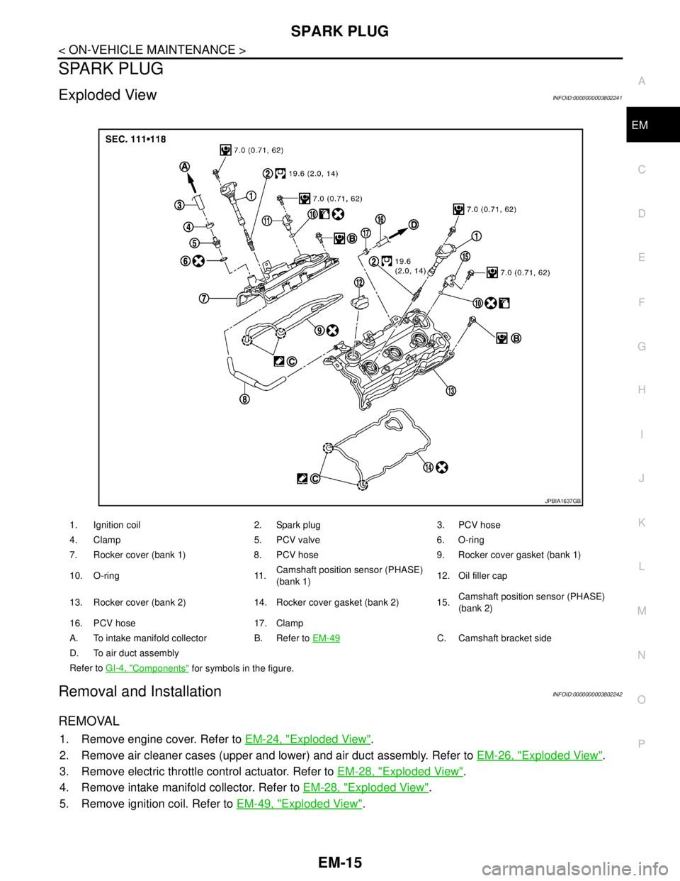
Exploded ViewINFOID:0000000003802241
Removal and InstallationINFOID:0000000003802242
REMOVAL
1. Remove engine cover. Refer to EM-24, "Exploded View".
2. Remove air cleaner cases (upper and lower) and air duct assembly. Refer to EM-26, "
Exploded View".
3. Remove electric throttle control actuator. Refer to EM-28, "
Exploded View".
4. Remove intake manifold collector. Refer to EM-28, "
Exploded View".
5. Remove ignition coil. Refer to EM-49, "
Exploded View".
1. Ignition coil 2. Spark plug 3. PCV hose
4. Clamp 5. PCV valve 6. O-ring
7. Rocker cover (bank 1) 8. PCV hose 9. Rocker cover gasket (bank 1)
10. O-ring 11.Camshaft position sensor (PHASE)
(bank 1)12. Oil filler cap
13. Rocker cover (bank 2) 14. Rocker cover gasket (bank 2) 15.Camshaft position sensor (PHASE)
(bank 2)
16. PCV hose 17. Clamp
A. To intake manifold collector B. Refer to EM-49
C. Camshaft bracket side
D. To air duct assembly
Refer to GI-4, "
Components" for symbols in the figure.
JPBIA1637GB
Page 1892 of 5121
CAMSHAFT VALVE CLEARANCE
EM-17
< ON-VEHICLE MAINTENANCE >
C
D
E
F
G
H
I
J
K
L
MA
EM
N
P O
CAMSHAFT VALVE CLEARANCE
Inspection and AdjustmentINFOID:0000000003802244
INSPECTION
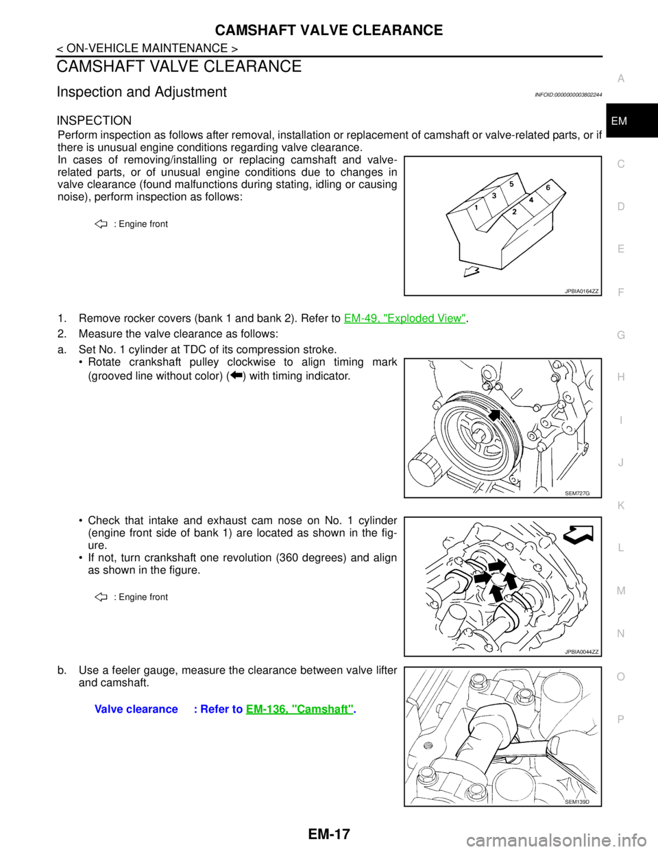
Perform inspection as follows after removal, installation or replacement of camshaft or valve-related parts, or if
there is unusual engine conditions regarding valve clearance.
In cases of removing/installing or replacing camshaft and valve-
related parts, or of unusual engine conditions due to changes in
valve clearance (found malfunctions during stating, idling or causing
noise), perform inspection as follows:
1. Remove rocker covers (bank 1 and bank 2). Refer to EM-49, "
Exploded View".
2. Measure the valve clearance as follows:
a. Set No. 1 cylinder at TDC of its compression stroke.
Rotate crankshaft pulley clockwise to align timing mark
(grooved line without color) ( ) with timing indicator.
Check that intake and exhaust cam nose on No. 1 cylinder
(engine front side of bank 1) are located as shown in the fig-
ure.
If not, turn crankshaft one revolution (360 degrees) and align
as shown in the figure.
b. Use a feeler gauge, measure the clearance between valve lifter
and camshaft.
: Engine front
JPBIA0164ZZ
SEM727G
: Engine front
JPBIA0044ZZ
Valve clearance : Refer to EM-136, "Camshaft".
SEM139D