2008 NISSAN TEANA engine
[x] Cancel search: enginePage 1868 of 5121
![NISSAN TEANA 2008 Service Manual PRECAUTIONS
EC-407
< PRECAUTION >[VQ25DE, VQ35DE]
C
D
E
F
G
H
I
J
K
L
MA
EC
N
P O
When connecting or disconnecting pin connectors into or
from ECM, never damage pin terminals (bends or break).
Check NISSAN TEANA 2008 Service Manual PRECAUTIONS
EC-407
< PRECAUTION >[VQ25DE, VQ35DE]
C
D
E
F
G
H
I
J
K
L
MA
EC
N
P O
When connecting or disconnecting pin connectors into or
from ECM, never damage pin terminals (bends or break).
Check](/manual-img/5/57391/w960_57391-1867.png)
PRECAUTIONS
EC-407
< PRECAUTION >[VQ25DE, VQ35DE]
C
D
E
F
G
H
I
J
K
L
MA
EC
N
P O
When connecting or disconnecting pin connectors into or
from ECM, never damage pin terminals (bends or break).
Check that there are not any bends or breaks on ECM pin ter-
minal, when connecting pin connectors.
Securely connect ECM harness connectors.
A poor connection can cause an extremely high (surge) volt-
age to develop in coil and condenser, thus resulting in dam-
age to ICs.
Keep engine control system harness at least 10 cm (4 in) away
from adjacent harness, to prevent engine control system mal-
functions due to receiving external noise, degraded operation
of ICs, etc.
Keep engine control system parts and harness dry.
Before replacing ECM, perform ECM Terminals and Reference
Value inspection and check ECM functions properly. Refer to
EC-357, "
Reference Value".
Handle mass air flow sensor carefully to avoid damage.
Never clean mass air flow sensor with any type of detergent.
Never disassemble electric throttle control actuator.
Even a slight leak in the air intake system can cause serious
incidents.
Never shock or jar the camshaft position sensor (PHASE),
crankshaft position sensor (POS).
After performing each TROUBLE DIAGNOSIS, perform DTC
Confirmation Procedure or Component Function Check.
The DTC should not be displayed in the DTC Confirmation
Procedure if the repair is completed. The Component Func-
tion Check should be a good result if the repair is completed.
PBIB0090E
MEF040D
SAT652J
Page 1869 of 5121
![NISSAN TEANA 2008 Service Manual EC-408
< PRECAUTION >[VQ25DE, VQ35DE]
PRECAUTIONS
When measuring ECM signals with a circuit tester, never allow
the two tester probes to contact.
Accidental contact of probes will cause a short circu NISSAN TEANA 2008 Service Manual EC-408
< PRECAUTION >[VQ25DE, VQ35DE]
PRECAUTIONS
When measuring ECM signals with a circuit tester, never allow
the two tester probes to contact.
Accidental contact of probes will cause a short circu](/manual-img/5/57391/w960_57391-1868.png)
EC-408
< PRECAUTION >[VQ25DE, VQ35DE]
PRECAUTIONS
When measuring ECM signals with a circuit tester, never allow
the two tester probes to contact.
Accidental contact of probes will cause a short circuit and
damage the ECM power transistor.
Never use ECM ground terminals when measuring input/out-
put voltage. Doing so may result in damage to the ECM's tran-
sistor. Use a ground other than ECM terminals, such as the
ground.
B1 indicates bank 1, B2 indicates bank 2 as shown in the fig-
ure.
Never operate fuel pump when there is no fuel in lines.
Tighten fuel hose clamps to the specified torque.
Never depress accelerator pedal when starting.
Immediately after starting, never rev up engine unnecessarily.
Never rev up engine just prior to shutdown.
SEF348N
SEC893C
SEF709Y
Page 1871 of 5121
![NISSAN TEANA 2008 Service Manual EC-410
< PREPARATION >[VQ25DE, VQ35DE]
PREPARATION
PREPARATION
PREPARATION
Special Service ToolsINFOID:0000000003943273
Commercial Service ToolsINFOID:0000000003943274
Tool name Description
Fuel tube NISSAN TEANA 2008 Service Manual EC-410
< PREPARATION >[VQ25DE, VQ35DE]
PREPARATION
PREPARATION
PREPARATION
Special Service ToolsINFOID:0000000003943273
Commercial Service ToolsINFOID:0000000003943274
Tool name Description
Fuel tube](/manual-img/5/57391/w960_57391-1870.png)
EC-410
< PREPARATION >[VQ25DE, VQ35DE]
PREPARATION
PREPARATION
PREPARATION
Special Service ToolsINFOID:0000000003943273
Commercial Service ToolsINFOID:0000000003943274
Tool name Description
Fuel tube adapter Measuring fuel pressure
PBIB3043E
Tool name Description
Quick connector re-
leaseRemoves fuel tube quick connectors in engine
room
Socket wrench Removes and installing engine coolant tempera-
ture sensor
Oxygen sensor thread
cleanerReconditions the exhaust system threads before
installing a new oxygen sensor. Use with anti-
seize lubricant shown below.
a: 18 mm diameter with pitch 1.5 mm for Zirco-
nia Oxygen Sensor
b: 12 mm diameter with pitch 1.25 mm for Tita-
nia Oxygen Sensor
Anti-seize lubricant
i.e.: (Permatex
TM
133AR or equivalent
meeting MIL specifica-
tion MIL-A-907)Lubricates oxygen sensor thread cleaning tool
when reconditioning exhaust system threads.
PBIC0198E
S-NT705
AEM488
S-NT779
Page 1872 of 5121
![NISSAN TEANA 2008 Service Manual FUEL PRESSURE
EC-411
< ON-VEHICLE MAINTENANCE >[VQ25DE, VQ35DE]
C
D
E
F
G
H
I
J
K
L
MA
EC
N
P O
ON-VEHICLE MAINTENANCE
FUEL PRESSURE
InspectionINFOID:0000000003856884
FUEL PRESSURE RELEASE
With CONSU NISSAN TEANA 2008 Service Manual FUEL PRESSURE
EC-411
< ON-VEHICLE MAINTENANCE >[VQ25DE, VQ35DE]
C
D
E
F
G
H
I
J
K
L
MA
EC
N
P O
ON-VEHICLE MAINTENANCE
FUEL PRESSURE
InspectionINFOID:0000000003856884
FUEL PRESSURE RELEASE
With CONSU](/manual-img/5/57391/w960_57391-1871.png)
FUEL PRESSURE
EC-411
< ON-VEHICLE MAINTENANCE >[VQ25DE, VQ35DE]
C
D
E
F
G
H
I
J
K
L
MA
EC
N
P O
ON-VEHICLE MAINTENANCE
FUEL PRESSURE
InspectionINFOID:0000000003856884
FUEL PRESSURE RELEASE
With CONSULT-III
1. Turn ignition switch ON.
2. Perform “FUEL PRESSURE RELEASE” in “WORK SUPPORT” mode with CONSULT-III.
3. Start engine.
4. After engine stalls, crank it 2 or 3 times to release all fuel pressure.
5. Turn ignition switch OFF.
Without CONSULT-III
1. Remove fuel pump fuse located in IPDM E/R.
2. Start engine.
3. After engine stalls, crank it 2 or 3 times to release all fuel pressure.
4. Turn ignition switch OFF.
5. Reinstall fuel pump fuse after servicing fuel system.
FUEL PRESSURE CHECK
CAUTION:
Before disconnecting fuel line, release fuel pressure from fuel line to eliminate danger.
NOTE:
Prepare pans or saucers under the disconnected fuel line because the fuel may spill out. The fuel
pressure cannot be completely released because J32 models do not have fuel return system.
Be careful not to scratch or get the fuel hose connection area dirty when servicing, so that the quick
connector o-ring maintains seal ability.
1. Release fuel pressure to zero.
2. Remove fuel hose using Quick Connector Release.
Do not twist or kink fuel hose because it is plastic hose.
Keep fuel hose connections clean.
3. Install Fuel pressure adapter (B) and Fuel pressure gauge (A)
as shown in figure.
Do not distort or bend fuel rail tube when installing fuel pres-
sure gauge adapter.
When reconnecting fuel hose, check the original fuel hose for
damage and abnormality.
4. Turn ignition switch ON (reactivate fuel pump) and check for fuel
leakage.
5. Start engine and check for fuel leakage.
6. Read the indication of fuel pressure gauge kit.
During fuel pressure check, check for fuel leakage from fuel
connection every 3 minutes.
7. If result is unsatisfactory, go to next step.
8. Check the following.
Fuel hoses and fuel tubes for clogging
Fuel filter for clogging
Fuel pump
Fuel pressure regulator for clogging
9. If OK, replace fuel pressure regulator.
If NG, repair or replace malfunctioning part.
At idling
: Approximately 350 kPa (3.5 bar, 3.57 kg/cm2, 51 psi)
JMBIA1392ZZ
Page 1875 of 5121
![NISSAN TEANA 2008 Service Manual EC-414
< SERVICE DATA AND SPECIFICATIONS (SDS) [VQ25DE, VQ35DE]
SERVICE DATA AND SPECIFICATIONS (SDS)
SERVICE DATA AND SPECIFICATIONS (SDS)
SERVICE DATA AND SPECIFICATIONS (SDS)
Idle SpeedINFOID:00000 NISSAN TEANA 2008 Service Manual EC-414
< SERVICE DATA AND SPECIFICATIONS (SDS) [VQ25DE, VQ35DE]
SERVICE DATA AND SPECIFICATIONS (SDS)
SERVICE DATA AND SPECIFICATIONS (SDS)
SERVICE DATA AND SPECIFICATIONS (SDS)
Idle SpeedINFOID:00000](/manual-img/5/57391/w960_57391-1874.png)
EC-414
< SERVICE DATA AND SPECIFICATIONS (SDS) [VQ25DE, VQ35DE]
SERVICE DATA AND SPECIFICATIONS (SDS)
SERVICE DATA AND SPECIFICATIONS (SDS)
SERVICE DATA AND SPECIFICATIONS (SDS)
Idle SpeedINFOID:0000000003856889
Ignition TimingINFOID:0000000003856890
Calculated Load ValueINFOID:0000000003856891
Mass Air Flow SensorINFOID:0000000003856892
*: Engine is warmed up to normal operating temperature and running under no load.Condition Specification
No load (in P or N position) 600 ± 50 rpm
Condition Specification
No load (in P or N position) 12 ± 5° BTDC
Condition Specification (Using CONSULT-III or GST)
At idle10 – 35 %
At 2,500 rpm10 – 35 %
Supply voltageBattery voltage (11 – 14 V)
Output voltage at idle (in N position) 0.9 – 1.2 V*
Mass air flow (Using CONSULT-III or GST)2.0 – 6.0 g·m/sec at idle*
7.0 – 20.0 g·m/sec at 2,500 rpm*
Page 1876 of 5121

EM-1
ENGINE
C
D
E
F
G
H
I
J
K
L
M
SECTION EM
A
EM
N
O
P
CONTENTS
ENGINE MECHANICAL
SYMPTOM DIAGNOSIS ...............................3
NOISE, VIBRATION AND HARSHNESS
(NVH) TROUBLESHOOTING .............................
3
NVH Troubleshooting - Engine Noise .......................3
Use the Chart Below to Help You Find the Cause
of the Symptom .........................................................
4
PRECAUTION ...............................................5
PRECAUTIONS ...................................................5
Precaution for Procedure without Cowl Top Cover ......5
Precaution for Supplemental Restraint System
(SRS) "AIR BAG" and "SEAT BELT PRE-TEN-
SIONER" ...................................................................
5
Precaution Necessary for Steering Wheel Rota-
tion after Battery Disconnect .....................................
5
Precaution for Drain Engine Coolant and Engine
Oil ..............................................................................
6
Precaution for Disconnecting Fuel Piping .................6
Precaution for Removal and Disassembly ................6
Precaution for Inspection, Repair and Replace-
ment ..........................................................................
6
Precaution for Assembly and Installation ..................6
Precaution for Angle Tightening ................................6
Precaution for Liquid Gasket .....................................7
PREPARATION ............................................8
PREPARATION ...................................................8
Special Service Tool .................................................8
Commercial Service Tool ..........................................9
ON-VEHICLE MAINTENANCE ....................12
DRIVE BELT .......................................................12
Exploded View ........................................................12
Checking .................................................................12
Tension Adjustment ................................................12
Removal and Installation .........................................12
AIR CLEANER FILTER ......................................14
Removal and Installation .........................................14
SPARK PLUG ...................................................15
Exploded View .........................................................15
Removal and Installation .........................................15
Inspection ................................................................16
CAMSHAFT VALVE CLEARANCE ..................17
Inspection and Adjustment ......................................17
COMPRESSION PRESSURE ...........................22
Inspection ................................................................22
ON-VEHICLE REPAIR .................................24
ENGINE COVER ...............................................24
Exploded View .........................................................24
Removal and Installation .........................................24
DRIVE BELT AUTO TENSIONER AND IDLER
PULLEY .............................................................
25
Exploded View .........................................................25
Removal and Installation .........................................25
AIR CLEANER AND AIR DUCT .......................26
Exploded View .........................................................26
Removal and Installation .........................................26
Inspection ................................................................27
INTAKE MANIFOLD COLLECTOR ..................28
Exploded View .........................................................28
Removal and Installation .........................................29
INTAKE MANIFOLD .........................................32
Exploded View .........................................................32
Removal and Installation .........................................32
Inspection ................................................................33
EXHAUST MANIFOLD AND THREE WAY
CATALYST ........................................................
34
Exploded View .........................................................34
Removal and Installation .........................................34
Inspection ................................................................37
Page 1877 of 5121

EM-2
OIL PAN AND OIL STRAINER ..........................38
Exploded View ........................................................38
Removal and Installation ........................................38
Inspection ...............................................................42
FUEL INJECTOR AND FUEL TUBE .................44
Exploded View ........................................................44
Removal and Installation ........................................44
Inspection ...............................................................48
IGNITION COIL, SPARK PLUG AND ROCK-
ER COVER .........................................................
49
Exploded View ........................................................49
Removal and Installation ........................................49
TIMING CHAIN ..................................................52
Exploded View ........................................................52
Removal and Installation ........................................53
Inspection ...............................................................65
REMOVAL AND INSTALLATION ...............67
ENGINE ASSEMBLY .........................................67
Exploded View ........................................................67
Removal and Installation ........................................67
Inspection ...............................................................75
DISASSEMBLY AND ASSEMBLY .............76
ENGINE STAND SETTING ................................76
Setting ....................................................................76
ENGINE UNIT ....................................................78
Disassembly ...........................................................78
Assembly ................................................................78
REAR TIMING CHAIN CASE ............................79
Exploded View ........................................................79
Disassembly and Assembly ....................................80
CAMSHAFT .......................................................84
Exploded View ........................................................84
Removal and Installation ........................................84
Inspection ...............................................................88
OIL SEAL ...........................................................93
VALVE OIL SEAL .....................................................93
VALVE OIL SEAL : Removal and Installation .........93
FRONT OIL SEAL .....................................................93
FRONT OIL SEAL : Removal and Installation ........93
REAR OIL SEAL .......................................................94
REAR OIL SEAL : Removal and Installation ...........94
CYLINDER HEAD ..............................................96
Exploded View ........................................................96
Removal and Installation .........................................97
Disassembly and Assembly ..................................100
Inspection ..............................................................104
CYLINDER BLOCK ..........................................107
Exploded View ......................................................107
Disassembly and Assembly ..................................110
Inspection ..............................................................119
HOW TO SELECT PISTON AND BEARING ...129
Description ............................................................129
Piston ....................................................................129
Connecting Rod Bearing .....................................130
Main Bearing ........................................................132
SERVICE DATA AND SPECIFICATIONS
(SDS) .........................................................
135
SERVICE DATA AND SPECIFICATIONS
(SDS) ................................................................
135
General Specification ...........................................135
Drive Belt ..............................................................136
Spark Plug ............................................................136
Intake Manifold ......................................................136
Exhaust Manifold ..................................................136
Camshaft ...............................................................136
Cylinder Head ......................................................139
Cylinder Block ......................................................143
Main Bearing ........................................................146
Connecting Rod Bearing .....................................147
Page 1878 of 5121

NOISE, VIBRATION AND HARSHNESS (NVH) TROUBLESHOOTING
EM-3
< SYMPTOM DIAGNOSIS >
C
D
E
F
G
H
I
J
K
L
MA
EM
N
P O
SYMPTOM DIAGNOSIS
NOISE, VIBRATION AND HARSHNESS (NVH) TROUBLESHOOTING
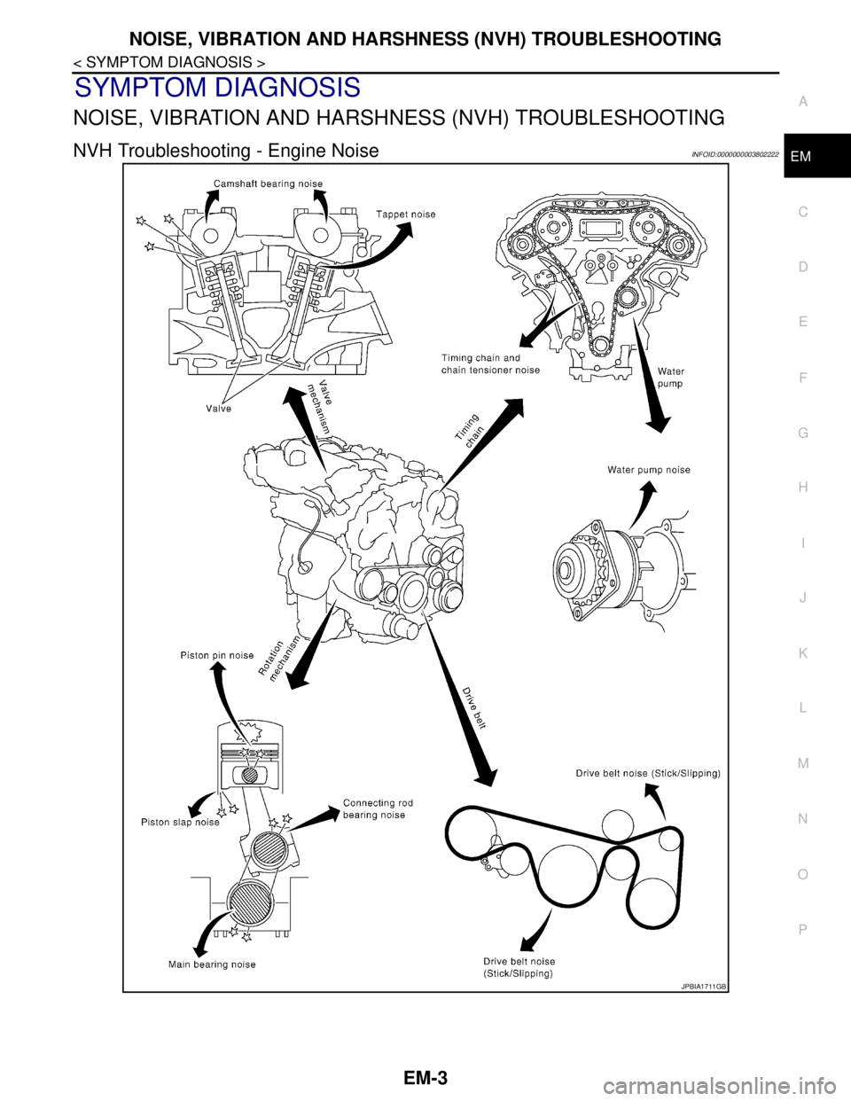
NVH Troubleshooting - Engine NoiseINFOID:0000000003802222
JPBIA1711GB