2008 NISSAN TEANA oil change
[x] Cancel search: oil changePage 3232 of 5121
MA-44
< SERVICE DATA AND SPECIFICATIONS (SDS)
SERVICE DATA AND SPECIFICATIONS (SDS)
SERVICE DATA AND SPECIFICATIONS (SDS)
SERVICE DATA AND SPECIFICATIONS (SDS)
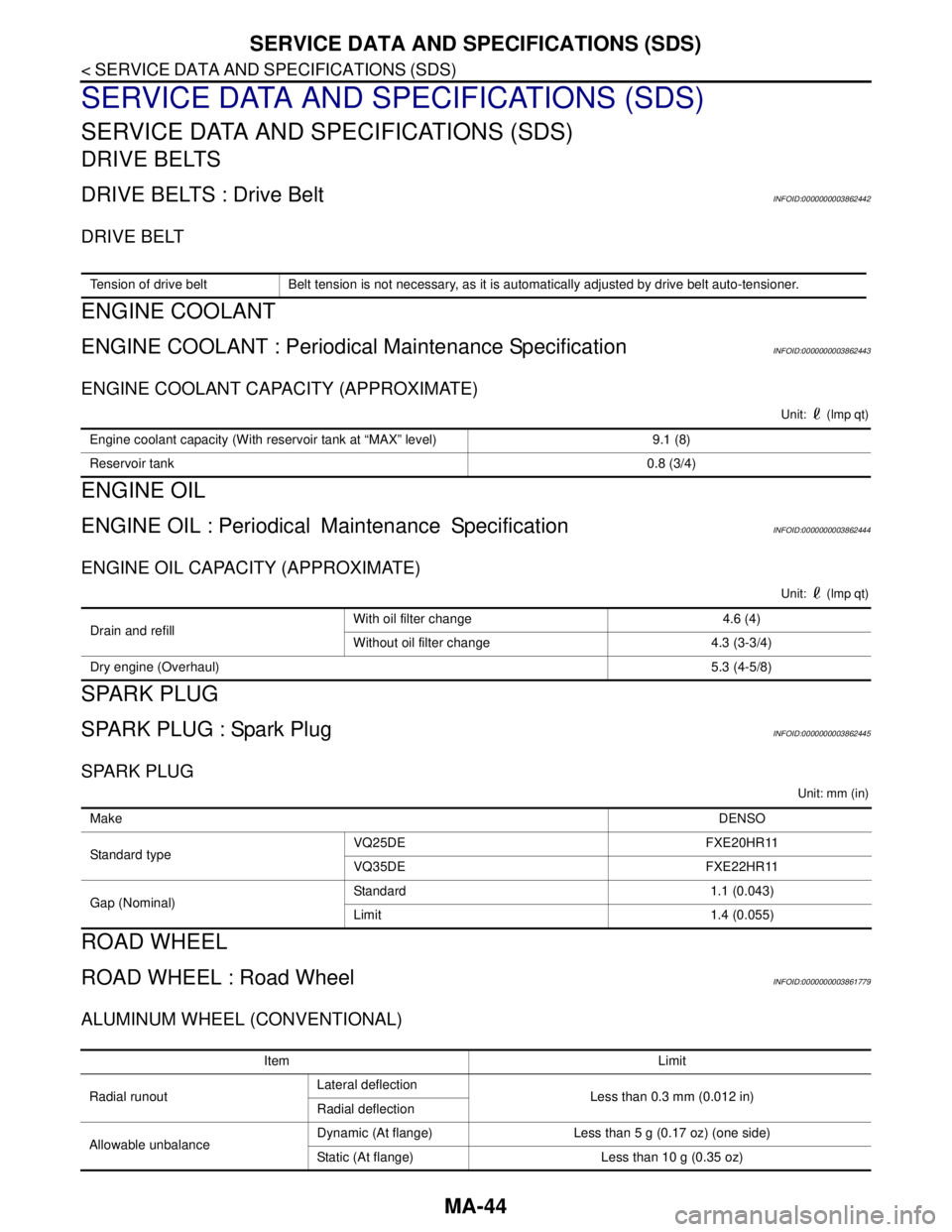
DRIVE BELTS
DRIVE BELTS : Drive BeltINFOID:0000000003862442
DRIVE BELT
ENGINE COOLANT
ENGINE COOLANT : Periodical Maintenance SpecificationINFOID:0000000003862443
ENGINE COOLANT CAPACITY (APPROXIMATE)
Unit: (lmp qt)
ENGINE OIL
ENGINE OIL : PeriodicalMaintenance SpecificationINFOID:0000000003862444
ENGINE OIL CAPACITY (APPROXIMATE)
Unit: (lmp qt)
SPARK PLUG
SPARK PLUG : Spark PlugINFOID:0000000003862445
SPARK PLUG
Unit: mm (in)
ROAD WHEEL
ROAD WHEEL : Road WheelINFOID:0000000003861779
ALUMINUM WHEEL (CONVENTIONAL)
Tension of drive belt Belt tension is not necessary, as it is automatically adjusted by drive belt auto-tensioner.
Engine coolant capacity (With reservoir tank at “MAX” level) 9.1 (8)
Reservoir tank0.8 (3/4)
Drain and refill With oil filter change 4.6 (4)
Without oil filter change 4.3 (3-3/4)
Dry engine (Overhaul)5.3 (4-5/8)
MakeDENSO
Standard typeVQ25DE FXE20HR11
VQ35DE FXE22HR11
Gap (Nominal)Standard 1.1 (0.043)
Limit 1.4 (0.055)
Item Limit
Radial runoutLateral deflection
Less than 0.3 mm (0.012 in)
Radial deflection
Allowable unbalanceDynamic (At flange) Less than 5 g (0.17 oz) (one side)
Static (At flange) Less than 10 g (0.35 oz)
Page 3283 of 5121

MWI
METER SYSTEM
MWI-29
< FUNCTION DIAGNOSIS >
C
D
E
F
G
H
I
J
K
L
MB A
O
P
NOTE:
The ambient sensor input value that is displayed on “Data Monitor” of CONSULT-III is the value before the
correction. It may not match the indicated temperature on the information display.
The ambient temperature may be indicated higher than the actual temperature, depending on heat in the
engine, the road surface temperature, and so on.
SETTING
Setting item list
* : Press and hold the switch (1 second or more).Items Setting range Setting unit Description
ALERTTIME TO REST No setting - 6 hours30 minutes,
[60 minutes]*Time to rest is displayed on the informa-
tion display if the vehicle reached the set
travel distance.
ICY ON/OFF —Low outside temp is displayed on the in-
formation display if the ambient tempera-
ture is 3°C (37°F) or less.
MAINTENANCEENGINE OIL No setting - 30,000 km500 km,
1000 km*The engine oil replacement interval is dis-
played on the information display if the ve-
hicle reached the set distance.
OIL FILTER No setting - 30,000 km500 km,
1000 km*The oil filter replacement interval is dis-
played on the information display if the ve-
hicle reached the set distance.
TIRE No setting - 30,000 km500 km,
1000 km*The tire replacement interval is displayed
on the information display if the vehicle
reached the set distance.
OTHER No setting - 30,000 km500 km,
1000 km*The other replacement interval is dis-
played on the information display if the ve-
hicle reached the set distance.
UNIT km, km/l / km, l/100km — The unit setting can be changed.
Page 3321 of 5121

MWI
COMBINATION METER
MWI-67
< ECU DIAGNOSIS >
C
D
E
F
G
H
I
J
K
L
MB A
O
P
DTC IndexINFOID:0000000003792591
Function Specifications
Speedometer
Reset to zero by suspending communication. Tachometer
Water temperature gauge
Illumination controlWhen suspending communication, changes to nighttime
mode.
Information displayDoor open warning
The display turns off by suspending communication. Trunk open warning
Parking brake release warning
Instantaneous fuel warning When reception time of an abnormal signal is 2 seconds or
less, the last received datum is used for calculation to indi-
cate the result.
When reception time of an abnormal signal is more than two
seconds, the last result calculated during normal condition
is indicated. Average fuel consumption
Average vehicle speed
Travel distance
Buzzer The buzzer turns off by suspending communication.
Warning lamp/indicator
lampABS warning lamp
The lamp turns on by suspending communication. VDC OFF indicator lamp
SLIP indicator lamp
Brake warning lamp
High beam indicator lamp
The lamp turns off by suspending communication. Front fog light indicator lamp
Rear fog light indicator lamp
Turn signal indicator lamp
Light indicator lamp
Oil pressure warning lamp
Malfunction indicator lamp
CRUISE indicator lamp
SPORT indicator lamp
Key warning lamp
Display contents of CONSULT-III Diagnostic item is detected when ... Refer to
CAN COMM CIRCUIT
[U1000]When combination meter is not transmitting or receiving CAN communication signal
for 2 seconds or more.MWI-37,
"Diagnosis
Procedure"
CONTROL UNIT (CAN)
[U1010]When detecting error during the initial diagnosis of the CAN controller of combina-
tion meter.MWI-38, "Diagnosis
Procedure"
VEHICLE SPEED
[B2205]The abnormal vehicle speed signal is input from the ABS actuator and electric unit
(control unit) for 2 seconds or more.MWI-39, "Diagnosis
Procedure"
ENGINE SPEED
[B2267]If ECM continuously transmits abnormal engine speed signals for 2 seconds or
more.MWI-40, "Diagnosis
Procedure"
WATER TEMP
[B2268]If ECM continuously transmits abnormal engine coolant temperature signals for 60
seconds or more.MWI-41, "Diagnosis
Procedure"
Page 4492 of 5121
![NISSAN TEANA 2008 Service Manual MECHANICAL SYSTEM
TM-19
< FUNCTION DIAGNOSIS >[CVT: RE0F09B]
C
E
F
G
H
I
J
K
L
MA
B
TM
N
O
P
CVT fluid temperature sensor
Secondary pressure sensor
ROM assembly
Component DescriptionINFOID:00000](/manual-img/5/57391/w960_57391-4491.png "NISSAN TEANA 2008 Service Manual MECHANICAL SYSTEM
TM-19
< FUNCTION DIAGNOSIS >[CVT: RE0F09B]
C
E
F
G
H
I
J
K
L
MA
B
TM
N
O
P
CVT fluid temperature sensor
Secondary pressure sensor
ROM assembly
Component DescriptionINFOID:00000")
MECHANICAL SYSTEM
TM-19
< FUNCTION DIAGNOSIS >[CVT: RE0F09B]
C
E
F
G
H
I
J
K
L
MA
B
TM
N
O
P
CVT fluid temperature sensor
Secondary pressure sensor
ROM assembly
Component DescriptionINFOID:0000000003848923
Item Function
Torque converterThe torque converter is the device that increases the engine torque as well as the con-
ventional AT and transmits it to the transaxle.
Oil pumpThe adoption of a trochoidal oil pump with a flow control valve actuated directly by the
engine enables the sufficient discharge from an oil pump in the low-rpm range and the
adequate discharge adjustments in the high-rpm range.
Planetary gear
Perform the transmission of drive power and the switching of forward/backward move-
ment. Forward clutch
Reverse brake
Primary pulley It is composed of a pair of pulleys (the groove width is changed freely in the axial direc-
tion) and the steel belt (the steel star wheels are placed continuously and the belt is guid-
ed with the multilayer steel rings on both sides). The groove width changes according to
wrapping radius of steel belt and pulley from low status to overdrive status continuously
with non-step. It is controlled with the oil pressures of primary pulley and secondary pul-
ley. Secondary pulley
Steel belt
Output gear
Reduction gear consists of primary deceleration (output gear and idler gear in pair) and
secondary deceleration (reduction gear and final gear in pair). Each of them uses a he-
lical gear. Idler gear
Reduction gear
Final gear
Differential
Manual shaft
The parking rod rotates the parking pole and the parking pole engages with the parking
gear when the manual shaft is in “P” position. As a result the parking gear and the output
axis are fixed. Parking rod
Parking pawl
Parking gear
Page 4570 of 5121
![NISSAN TEANA 2008 Service Manual P1777 STEP MOTOR
TM-97
< COMPONENT DIAGNOSIS >[CVT: RE0F09B]
C
E
F
G
H
I
J
K
L
MA
B
TM
N
O
P
P1777 STEP MOTOR
DescriptionINFOID:0000000003849040
The step motor changes the step by turning 4 coils ON/O](/manual-img/5/57391/w960_57391-4569.png "NISSAN TEANA 2008 Service Manual P1777 STEP MOTOR
TM-97
< COMPONENT DIAGNOSIS >[CVT: RE0F09B]
C
E
F
G
H
I
J
K
L
MA
B
TM
N
O
P
P1777 STEP MOTOR
DescriptionINFOID:0000000003849040
The step motor changes the step by turning 4 coils ON/O")
P1777 STEP MOTOR
TM-97
< COMPONENT DIAGNOSIS >[CVT: RE0F09B]
C
E
F
G
H
I
J
K
L
MA
B
TM
N
O
P
P1777 STEP MOTOR
DescriptionINFOID:0000000003849040
The step motor changes the step by turning 4 coils ON/OFF according to the signal from TCM. As a result, the
flow of line pressure to primary pulley is changed and pulley ratio is controlled.
DTC LogicINFOID:0000000003849041
DTC DETECTION LOGIC
DTC CONFIRMATION PROCEDURE
CAUTION:
Always drive vehicle at a safe speed.
NOTE:
If “DTC CONFIRMATION PROCEDURE” has been previously performed, always turn ignition switch OFF.
Then wait at least 10 seconds before performing the next test.
1.CHECK DTC DETECTION
With CONSULT-III
1. Start engine.
2. Drive vehicle for at least 5 consecutive seconds.
3. Perform “Self-Diagnostic Results” mode for “TRANSMISSION”.
With GST
Follow the procedure “With CONSULT-III”.
Is
“P1777 STEP MOTR CIRC” detected?
YES >> Go to TM-97, "Diagnosis Procedure".
NO >> Check intermittent incident. Refer to GI-35, "
Intermittent Incident".
Diagnosis ProcedureINFOID:0000000003849042
1.CHECK STEP MOTOR CIRCUIT
1. Turn ignition switch OFF.
2. Disconnect TCM connector.
3. Check resistance between TCM vehicle side harness connector terminals.
4. Check resistance between TCM vehicle side harness connector terminals and ground.
DTCItem
(CONSULT-III screen term)Malfunction is detected when... Possible cause
P1777 STEP MOTR CIRCEach coil of the step motor is not energized
properly due to an open or a short. Harness or connectors
(Step motor circuit is open or shorted.)
Step motor
TCM vehicle side harness connector
Resistance (Approx.)
Connector Terminal
F2327 28
30.0 Ω
29 30
TCM vehicle side harness connector
GroundResistance (Approx.)
Connector Terminal
F2327
15.0 Ω 28
29
30
Page 4573 of 5121
![NISSAN TEANA 2008 Service Manual TM-100
< COMPONENT DIAGNOSIS >[CVT: RE0F09B]
P1778 STEP MOTOR - FUNCTION
P1778 STEP MOTOR - FUNCTION
DescriptionINFOID:0000000003849044
The step motor changes the step by turning 4 coils ON/OFF acco](/manual-img/5/57391/w960_57391-4572.png "NISSAN TEANA 2008 Service Manual TM-100
< COMPONENT DIAGNOSIS >[CVT: RE0F09B]
P1778 STEP MOTOR - FUNCTION
P1778 STEP MOTOR - FUNCTION
DescriptionINFOID:0000000003849044
The step motor changes the step by turning 4 coils ON/OFF acco")
TM-100
< COMPONENT DIAGNOSIS >[CVT: RE0F09B]
P1778 STEP MOTOR - FUNCTION
P1778 STEP MOTOR - FUNCTION
DescriptionINFOID:0000000003849044
The step motor changes the step by turning 4 coils ON/OFF according to the signal from TCM. As a result,
the flow of line pressure to primary pulley is changed and pulley ratio is controlled.
This diagnosis item is detected when the electrical system is OK, but the mechanical system is NG.
This diagnosis item is detected when the state of the changing of the speed mechanism in the unit does not
operate normally.
DTC LogicINFOID:0000000003849045
DTC DETECTION LOGIC
DTC CONFIRMATION PROCEDURE
CAUTION:
Always drive vehicle at a safe speed.
Before starting “DTC CONFIRMATION PROCEDURE”, confirm “Hi” or “Mid” or “Low” fixation by
“PRI SPEED” and “VEHICLE SPEED” on “Data Monitor”.
If hi-geared fixation occurred, go to TM-100, "
Diagnosis Procedure".
NOTE:
Immediately after performing any “DTC CONFIRMATION PROCEDURE”, always turn ignition switch OFF.
Then wait at least 10 seconds before performing the next test.
1.CHECK DTC DETECTION
With CONSULT-III
1. Turn ignition switch ON.
2. Select “Data Monitor” mode for “TRANSMISSION”.
3. Make sure that output voltage of CVT fluid temperature sensor is within the range below.
4. Start engine and maintain the following conditions for at least 30 consecutive seconds.
With GST
Follow the procedure “With CONSULT-III”.
Is
“P1778 STEP MOTR/FNC” detected?
YES >> Go to TM-100, "Diagnosis Procedure".
NO >> Check intermittent incident. Refer to GI-35, "
Intermittent Incident".
Diagnosis ProcedureINFOID:0000000003849046
1.CHECK STEP MOTOR SYSTEM
Check step motor system. Refer to TM-97, "
Description".
Is the inspection result normal?
DTCItem
(CONSULT-III screen term)Malfunction is detected when... Possible cause
P1778 STEP MOTR/FNCThere is a big difference between the num-
ber of steps for the stepping motor and for
the actual gear ratio.Ste p m ot or
ATF TEMP SEN : 1.0 – 2.0 V
If it is out of range, drive the vehicle to decrease the voltage (warm up the fluid) or stop engine to increase the voltage
(cool down the fluid)
Start test from 0 km/h (0 MPH)
Constant acceleration : Keep 30 sec or more
VEHICLE SPEED : 10 km/h (6 MPH) or more
ACC PEDAL OPEN : More than 1.0/8
RANGE : “D” position
ENG SPEED : 450 rpm or more
Page 4585 of 5121
![NISSAN TEANA 2008 Service Manual TM-112
< ECU DIAGNOSIS >[CVT: RE0F09B]
TCM
INH SW3Selector lever in “D” and “L” positions On
Selector lever in “P”, “R” and “N” positions Off
INH SW2Selector lever in “N”, “D](/manual-img/5/57391/w960_57391-4584.png "NISSAN TEANA 2008 Service Manual TM-112
< ECU DIAGNOSIS >[CVT: RE0F09B]
TCM
INH SW3Selector lever in “D” and “L” positions On
Selector lever in “P”, “R” and “N” positions Off
INH SW2Selector lever in “N”, “D")
TM-112
< ECU DIAGNOSIS >[CVT: RE0F09B]
TCM
INH SW3Selector lever in “D” and “L” positions On
Selector lever in “P”, “R” and “N” positions Off
INH SW2Selector lever in “N”, “D” and “L” positions On
Selector lever in “P” and “R” positions Off
INH SW1Selector lever in “R”, “N” and “D” positions On
Selector lever in “P” and “L” positions Off
BRAKE SWDepressed brake pedal On
Released brake pedal Off
FULL SWFully depressed accelerator pedal On
Released accelerator pedal Off
IDLE SWReleased accelerator pedal On
Fully depressed accelerator pedal Off
SPORT MODE SWWhile pushing sport mode switch On
Other conditions Off
INDLRNGSelector lever in “L” position On
Selector lever in other positions Off
INDDRNGSelector lever in “D” position On
Selector lever in other positions Off
INDNRNGSelector lever in “N” position On
Selector lever in other positions Off
INDRRNGSelector lever in “R” position On
Selector lever in other positions Off
INDPRNGSelector lever in “P” position On
Selector lever in other positions Off
SPORT MODE INDWhen sport mode On
Other conditions Off
SMCOIL D During driving Changes ON ⇔ OFF.
SMCOIL C During driving Changes ON ⇔ OFF.
SMCOIL B During driving Changes ON ⇔ OFF.
SMCOIL A During driving Changes ON ⇔ OFF.
LUSEL SOL OUTSelector lever in “P” and “N” positions On
Wait at least for 5 seconds with the selector lever
in “R”, “D” and “L” positionsOff
LUSEL SOL MONSelector lever in “P” and “N” positions On
Wait at least for 5 seconds with the selector lever
in “R”, “D” and “L” positionsOff
STRTR RLY OUTSelector lever in “P” and “N” positions On
Selector lever in other positions Off
STRTR RLY MONSelector lever in “P” and “N” positions On
Selector lever in other positions Off
VDC ONVDC operate On
Other conditions Off
TCS ONTCS operate On
Other conditions Off Item name Condition Display value (Approx.)
Page 4594 of 5121
![NISSAN TEANA 2008 Service Manual TCM
TM-121
< ECU DIAGNOSIS >[CVT: RE0F09B]
C
E
F
G
H
I
J
K
L
MA
B
TM
N
O
P Output Speed Sensor (Secondary Speed Sensor)
The shift pattern is changed in accordance with the throttle position when an un](/manual-img/5/57391/w960_57391-4593.png "NISSAN TEANA 2008 Service Manual TCM
TM-121
< ECU DIAGNOSIS >[CVT: RE0F09B]
C
E
F
G
H
I
J
K
L
MA
B
TM
N
O
P Output Speed Sensor (Secondary Speed Sensor)
The shift pattern is changed in accordance with the throttle position when an un")
TCM
TM-121
< ECU DIAGNOSIS >[CVT: RE0F09B]
C
E
F
G
H
I
J
K
L
MA
B
TM
N
O
P Output Speed Sensor (Secondary Speed Sensor)
The shift pattern is changed in accordance with the throttle position when an unexpected signal is sent from
the output speed sensor (secondary speed sensor) to the TCM. The sport mode is inhibited, and the transaxle
is put in “D”.
Input Speed Sensor (Primary Speed Sensor)
The shift pattern is changed in accordance with the throttle position and secondary speed (vehicle speed)
when an unexpected signal is sent from the input speed sensor (primary speed sensor) to the TCM. The sport
mode is inhibited, and the transaxle is put in “D”.
PNP Switch
If an unexpected signal is sent from the PNP switch to the TCM, the transaxle is put in “D”.
CVT Fluid Temperature Sensor
If an unexpected signal is sent from the CVT fluid temperature sensor to the TCM, the gear ratio in use before
receiving the unexpected signal is maintained or the gear ratio is controlled to keep engine speed under 5,000
rpm.
Transmission Fluid Pressure Sensor A (Secondary Pressure Sensor)
If an unexpected signal is sent from the transmission fluid pressure sensor A (secondary pressure sensor) to
the TCM, the secondary pressure feedback control is stopped and the offset value obtained before the non-
standard condition occurs is used to control line pressure.
If transmission fluid pressure sensor A (secondary pressure sensor) error signal is inputted to the TCM, sec-
ondary pressure feedback control stops, but line pressure is controlled normally.
Pressure Control Solenoid A (Line Pressure Solenoid Valve)
If an unexpected signal is sent from the solenoid valve to the TCM, the pressure control solenoid A (line pres-
sure solenoid valve) is turned OFF to achieve the maximum fluid pressure.
Pressure Control Solenoid B (Secondary Pressure Solenoid Valve)
If an unexpected signal is sent from the solenoid valve to the TCM, the pressure control solenoid B (secondary
pressure solenoid valve) is turned OFF to achieve the maximum fluid pressure.
Torque Converter Clutch Solenoid Valve
If an unexpected signal is sent from the solenoid valve to the TCM, the torque converter clutch solenoid valve
is turned OFF to cancel the lock-up.
Ste p M oto r
If an unexpected signal is sent from the step motor to the TCM, the step motor coil phases “A” through “D” are
all turned OFF to hold the gear ratio used just before the non-standard condition occurred.
CVT Lock-up Select Solenoid Valve
If an unexpected signal is sent from the solenoid valve to the TCM, the CVT lock-up select solenoid valve is
turned OFF to cancel the lock-up.
TCM Power Supply (Memory Back-up)
Transaxle assembly is protected by limiting the engine torque when the memory back-up power supply (for
controlling) from the battery is not supplied to the TCM. Normal status is restored when turning the ignition
switch OFF to ON after the normal power supply.
DTC Inspection Priority ChartINFOID:0000000003849062
If some DTCs are displayed at the same time, perform inspections one by one based on the following priority
chart.
NOTE:
If DTC “U1000 CAN COMM CIRCUIT” is indicated with other DTCs, start from a diagnosis for “DTC
U1000 CAN COMMUNICATION LINE”. Refer to TM-41
.
DTC IndexINFOID:0000000003849063
NOTE:
Priority Detected items (DTC)
1 U1000 CAN communication line
2 Except above