Page 3204 of 5121
MA-16
< ON-VEHICLE MAINTENANCE >
ENGINE MAINTENANCE
Watch water temperature gauge so as not to overheat engine.
9. Stop the engine and cool down to less than approximately 50°C (122°F).
Cool down using fan to reduce the time.
If necessary, refill radiator up to filler neck with engine coolant.
CAUTION:
Never adhere the engine coolant to electronic equipments. (alternator etc.)
10. Refill reservoir tank to “MAX” level line with engine coolant.
11. Repeat steps 7 through 10 two or more times with radiator cap installed until engine coolant level no
longer drops.
12. Check cooling system for leakage with engine running.
13. Warm up the engine, and check for sound of engine coolant flow while running engine from idle up to
3,000 rpm with heater temperature controller set at several position between “COOL” and “WARM”.
Sound may be noticeable at heater unit.
14. Repeat step 13 three times.
15. If sound is heard, bleed air from cooling system by repeating step 5, and steps from 7 to 14 until engine
coolant level no longer drops.
ENGINE COOLANT : FlushingINFOID:0000000003862452
1. Install reservoir tank if removed, and radiator drain plug.
CAUTION:
Be sure to clean drain plug and install with new O-ring.
If water drain plugs on cylinder block are removed, close and tighten them. Refer to EM-110, "
Dis-
assembly and Assembly".
2. Remove air duct assembly and air cleaner cases (upper and lower) assembly. Refer to EM-26, "
Exploded
View".
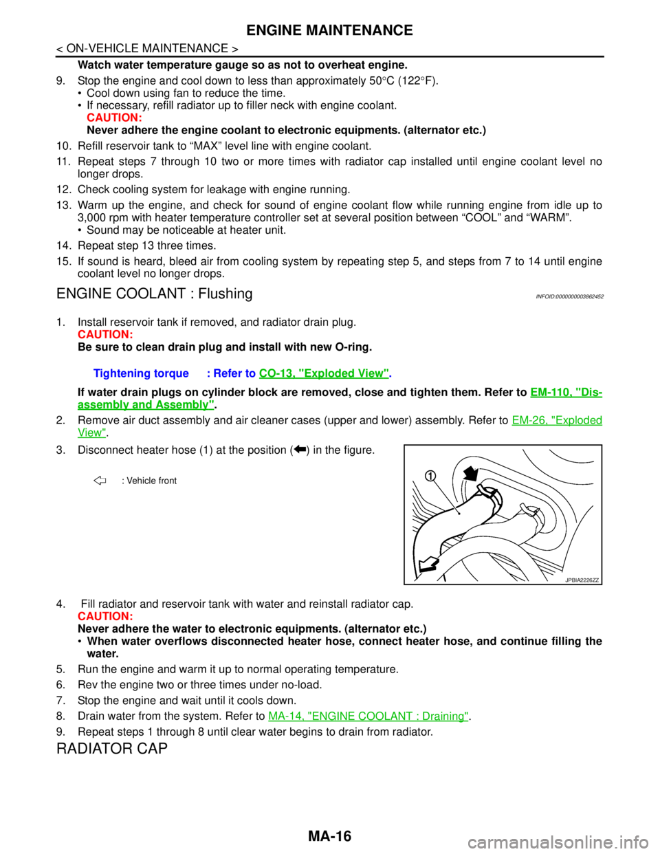
3. Disconnect heater hose (1) at the position ( ) in the figure.
4. Fill radiator and reservoir tank with water and reinstall radiator cap.
CAUTION:
Never adhere the water to electronic equipments. (alternator etc.)
When water overflows disconnected heater hose, connect heater hose, and continue filling the
water.
5. Run the engine and warm it up to normal operating temperature.
6. Rev the engine two or three times under no-load.
7. Stop the engine and wait until it cools down.
8. Drain water from the system. Refer to MA-14, "
ENGINE COOLANT : Draining".
9. Repeat steps 1 through 8 until clear water begins to drain from radiator.
RADIATOR CAP
Tightening torque : Refer to CO-13, "Exploded View".
: Vehicle front
JPBIA2226ZZ
Page 3232 of 5121
MA-44
< SERVICE DATA AND SPECIFICATIONS (SDS)
SERVICE DATA AND SPECIFICATIONS (SDS)
SERVICE DATA AND SPECIFICATIONS (SDS)
SERVICE DATA AND SPECIFICATIONS (SDS)
DRIVE BELTS
DRIVE BELTS : Drive BeltINFOID:0000000003862442
DRIVE BELT
ENGINE COOLANT
ENGINE COOLANT : Periodical Maintenance SpecificationINFOID:0000000003862443
ENGINE COOLANT CAPACITY (APPROXIMATE)
Unit: (lmp qt)
ENGINE OIL
ENGINE OIL : PeriodicalMaintenance SpecificationINFOID:0000000003862444
ENGINE OIL CAPACITY (APPROXIMATE)
Unit: (lmp qt)
SPARK PLUG
SPARK PLUG : Spark PlugINFOID:0000000003862445
SPARK PLUG
Unit: mm (in)
ROAD WHEEL
ROAD WHEEL : Road WheelINFOID:0000000003861779
ALUMINUM WHEEL (CONVENTIONAL)
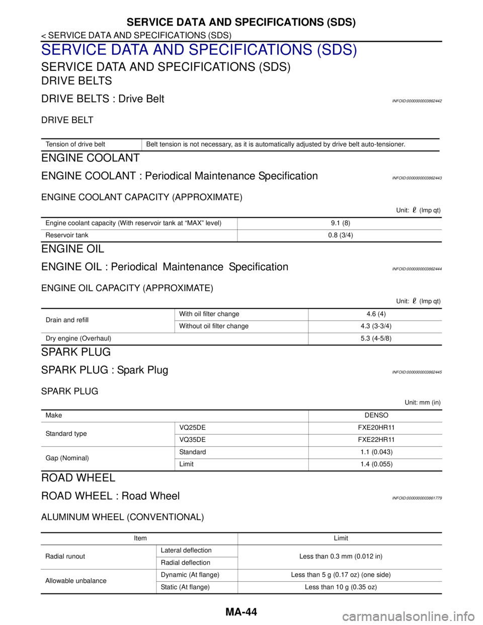
Tension of drive belt Belt tension is not necessary, as it is automatically adjusted by drive belt auto-tensioner.
Engine coolant capacity (With reservoir tank at “MAX” level) 9.1 (8)
Reservoir tank0.8 (3/4)
Drain and refill With oil filter change 4.6 (4)
Without oil filter change 4.3 (3-3/4)
Dry engine (Overhaul)5.3 (4-5/8)
MakeDENSO
Standard typeVQ25DE FXE20HR11
VQ35DE FXE22HR11
Gap (Nominal)Standard 1.1 (0.043)
Limit 1.4 (0.055)
Item Limit
Radial runoutLateral deflection
Less than 0.3 mm (0.012 in)
Radial deflection
Allowable unbalanceDynamic (At flange) Less than 5 g (0.17 oz) (one side)
Static (At flange) Less than 10 g (0.35 oz)
Page 4641 of 5121
TM-168
< REMOVAL AND INSTALLATION >[CVT: RE0F09B]
TRANSAXLE ASSEMBLY
REMOVAL AND INSTALLATION
TRANSAXLE ASSEMBLY
Exploded ViewINFOID:0000000003849108
Removal and InstallationINFOID:0000000003849109
WARNING:
Never remove the reservoir tank cap when the engine is hot. Serious burns could occur from high
pressure engine coolant escaping from the reservoir tank.
REMOVAL
1. Remove the engine, the transaxle assembly and front suspension member. Refer to EM-67, "Exploded
View".
2. Lift with hoist and separate engine, transaxle assembly from front suspension member. Refer to EM-67,
"Exploded View".
1. CVT fluid level gauge 2. CVT fluid charging pipe 3. O-ring
4. Transaxle assembly
A. For tightening torque, refer to TM-168, "
Removal and Installation".
Refer to GI-4, "
Components" for symbols in the figure.
JPDIA0799GB
Page 4805 of 5121
![NISSAN TEANA 2008 Service Manual TM-332
< REMOVAL AND INSTALLATION >[CVT: RE0F10A]
TRANSAXLE ASSEMBLY
REMOVAL AND INSTALLATION
TRANSAXLE ASSEMBLY
Exploded ViewINFOID:0000000003806551
Removal and InstallationINFOID:0000000003806552
WA](/manual-img/5/57391/w960_57391-4804.png "NISSAN TEANA 2008 Service Manual TM-332
< REMOVAL AND INSTALLATION >[CVT: RE0F10A]
TRANSAXLE ASSEMBLY
REMOVAL AND INSTALLATION
TRANSAXLE ASSEMBLY
Exploded ViewINFOID:0000000003806551
Removal and InstallationINFOID:0000000003806552
WA")
TM-332
< REMOVAL AND INSTALLATION >[CVT: RE0F10A]
TRANSAXLE ASSEMBLY
REMOVAL AND INSTALLATION
TRANSAXLE ASSEMBLY
Exploded ViewINFOID:0000000003806551
Removal and InstallationINFOID:0000000003806552
WARNING:
Never remove the reservoir tank cap when the engine is hot. Serious burns could occur from high
pressure engine coolant escaping from the reservoir tank.
REMOVAL
1. Remove the engine, the transaxle assembly and front suspension member. Refer to EM-67, "Exploded
View".
2. Lift with hoist and separate engine, transaxle assembly from front suspension member. Refer to EM-67,
"Exploded View".
3. Remove air breather hose. Refer to TM-328, "
Exploded View".
4. Remove CVT fluid level gauge and CVT fluid charging pipe.
5. Disconnect the following connectors:
Primary speed sensor connector
Secondary speed sensor connector
PNP switch connector
CVT unit connector
6. Remove crankshaft position sensor (POS). Refer to EM-38, "
Exploded View".
1. Transaxle assembly 2. O-ring 3. CVT fluid charging pipe
4. CVT fluid level gauge
A. For tightening torque, refer to TM-332, "
Removal and Installation".
B. To water outlet
Refer to GI-4, "
Components" for symbols in the figure.
JPDIA0736GB
Page:
< prev 1-8 9-16 17-24
![NISSAN TEANA 2008 Service Manual TM-168
< REMOVAL AND INSTALLATION >[CVT: RE0F09B]
TRANSAXLE ASSEMBLY
REMOVAL AND INSTALLATION
TRANSAXLE ASSEMBLY
Exploded ViewINFOID:0000000003849108
Removal and InstallationINFOID:0000000003849109
WA](/manual-img/5/57391/w960_57391-4640.png "NISSAN TEANA 2008 Service Manual TM-168
< REMOVAL AND INSTALLATION >[CVT: RE0F09B]
TRANSAXLE ASSEMBLY
REMOVAL AND INSTALLATION
TRANSAXLE ASSEMBLY
Exploded ViewINFOID:0000000003849108
Removal and InstallationINFOID:0000000003849109
WA")