2008 NISSAN TEANA coolant reservoir
[x] Cancel search: coolant reservoirPage 1413 of 5121
![NISSAN TEANA 2008 Service Manual RADIATOR CORE SUPPORT
DLK-197
< ON-VEHICLE REPAIR >[WITH INTELLIGENT KEY SYSTEM]
C
D
E
F
G
H
I
J
L
MA
B
DLK
N
O
P
13. Disconnect connector of refrigerant pressure sensor. Refer to HA-50, "Exploded Vie](/manual-img/5/57391/w960_57391-1412.png "NISSAN TEANA 2008 Service Manual RADIATOR CORE SUPPORT
DLK-197
< ON-VEHICLE REPAIR >[WITH INTELLIGENT KEY SYSTEM]
C
D
E
F
G
H
I
J
L
MA
B
DLK
N
O
P
13. Disconnect connector of refrigerant pressure sensor. Refer to HA-50, \"Exploded Vie")
RADIATOR CORE SUPPORT
DLK-197
< ON-VEHICLE REPAIR >[WITH INTELLIGENT KEY SYSTEM]
C
D
E
F
G
H
I
J
L
MA
B
DLK
N
O
P
13. Disconnect connector of refrigerant pressure sensor. Refer to HA-50, "Exploded View".
14. Remove mounting bolt, and then remove engine coolant reservoir tank. Refer to CO-13, "
Exploded View".
15. Remove mounting bolts, and then disconnect condenser pipe assembly. Refer to HA-48, "
Exploded
View".
16. Remove condenser. Refer to HA-46, "
Removal and Installation".
17. Remove mounting nut of radiator upper hose from radiator core support, and then remove radiator upper
hose and hood switch bracket. Refer to CO-25, "
Exploded View".
18. Disconnect radiator upper hose from radiator pipe (upper). Refer to CO-25, "
Exploded View".
19. Disconnect radiator lower hose (3). Refer to CO-25, "
Exploded View".
20. Disconnect CVT fluid cooler hose on radiator side. Refer to TM-165, "
Exploded View" (CVT: RE0F09B) or
TM-329, "
Exploded View" (CVT: RE0F10A).
21. Remove power steering oil cooler pipe from radiator core sup-
port at point shown by arrows in the figure.
22. Disconnect connectors of the following parts.
Cooling fan (RH/LH). Refer to CO-16, "
Exploded View".
Crash zone sensor. Refer to SR-18, "
Removal and Installation".
23. Remove radiator upper clip. Refer to CO-13, "
Exploded View".
24. Remove all harness clips from radiator core support.
CAUTION:
Never damage radiator.
25. Support hood assembly with a proper material to prevent it from falling.
WARNING:
Bodily injury may occur if no supporting rod is holding the hood open when removing the hood
stay.
26. Remove hood support rod. Refer to DLK-195, "
HOOD SUPPORT ROD : Removal and Installation".
27. Remove mounting bolts, and then remove radiator core support.
CAUTION:
Operate with two workers, because of its heavy weight.
Never damage power steering oil cooler pipe.
28. Remove the following parts after removing radiator core support.
Radiator lower hose, radiator upper hose, radiator pipe. Refer to CO-25, "
Exploded View".
Radiator. Refer to CO-13, "
Exploded View".
Cooling fan (RH/LH). Refer to CO-16, "
Exploded View".
Crash zone sensor. Refer to SR-18, "
Exploded View".
Power steering oil cooler pipe clip. Refer to ST-34, "
Exploded View".
INSTALLATION
Install in the reverse order of removal.
JMKIA2395ZZ
: harness clip
JMKIA2396ZZ
Page 1712 of 5121
![NISSAN TEANA 2008 Service Manual P1217 ENGINE OVER TEMPERATURE
EC-251
< COMPONENT DIAGNOSIS >[VQ25DE, VQ35DE]
C
D
E
F
G
H
I
J
K
L
MA
EC
N
P O
Check the coolant level in the reservoir tank and radiator.
Allow engine to cool before che](/manual-img/5/57391/w960_57391-1711.png "NISSAN TEANA 2008 Service Manual P1217 ENGINE OVER TEMPERATURE
EC-251
< COMPONENT DIAGNOSIS >[VQ25DE, VQ35DE]
C
D
E
F
G
H
I
J
K
L
MA
EC
N
P O
Check the coolant level in the reservoir tank and radiator.
Allow engine to cool before che")
P1217 ENGINE OVER TEMPERATURE
EC-251
< COMPONENT DIAGNOSIS >[VQ25DE, VQ35DE]
C
D
E
F
G
H
I
J
K
L
MA
EC
N
P O
Check the coolant level in the reservoir tank and radiator.
Allow engine to cool before checking coolant level.
Is the coolant level in the reservoir tank and/or radiator below the
proper range?
YES >> Go to EC-251, "Diagnosis Procedure".
NO >> GO TO 2.
2.PERFORM COMPONENT FUNCTION CHECK-II
Confirm whether customer filled the coolant or not.
Did customer fill the coolant?
YES >> Go to EC-251, "Diagnosis Procedure".
NO >> GO TO 3.
3.PERFORM COMPONENT FUNCTION CHECK-III
With CONSULT-III
1. Turn ignition switch ON.
2. Perform “COOLING FAN” in “ACTIVE TEST” mode with CONSULT-III.
3. Check that cooling fan motors-1 and -2 operate at each speed (LOW/MID/HI).
Without CONSULT-III
Perform IPDM E/R auto active test and check cooling fan motors operation, refer to PCS-11, "
Diagnosis
Description".
Is the inspection result normal?
YES >> INSPECTION END
NO >> Go to EC-251, "
Diagnosis Procedure".
Diagnosis ProcedureINFOID:0000000003856720
1.CHECK COOLING FAN OPERATION
With CONSULT-III
1. Turn ignition switch ON.
2. Perform “COOLING FAN” in “ACTIVE TEST” mode with CONSULT-III.
3. Check that cooling fans-1 and -2 operate at each speed (LOW/MID/HI).
Without CONSULT-III
1. Perform IPDM E/R auto active test and check cooling fan motors operation, refer to PCS-11, "
Diagnosis
Description".
2. Check that cooling fans-1 and -2 operate at each speed (Low/Middle/High).
Is the inspection result normal?
YES >> GO TO 2.
NO >> Go to EC-324, "
Diagnosis Procedure".
2.CHECK COOLING SYSTEM FOR LEAK-I
Check cooling system for leak. Refer to CO-8, "
Inspection".
Is leakage detected?
YES >> GO TO 3.
NO >> GO TO 4.
3.CHECK COOLING SYSTEM FOR LEAK-II
Check the following for leak.
Hose
Radiator
Water pump
SEF621W
Page 1713 of 5121
![NISSAN TEANA 2008 Service Manual EC-252
< COMPONENT DIAGNOSIS >[VQ25DE, VQ35DE]
P1217 ENGINE OVER TEMPERATURE
>> Repair or replace malfunctioning part.
4.CHECK RADIATOR CAP
Check radiator cap. Refer to CO-12, "
RADIATOR CAP : Inspect](/manual-img/5/57391/w960_57391-1712.png "NISSAN TEANA 2008 Service Manual EC-252
< COMPONENT DIAGNOSIS >[VQ25DE, VQ35DE]
P1217 ENGINE OVER TEMPERATURE
>> Repair or replace malfunctioning part.
4.CHECK RADIATOR CAP
Check radiator cap. Refer to CO-12, \"
RADIATOR CAP : Inspect")
EC-252
< COMPONENT DIAGNOSIS >[VQ25DE, VQ35DE]
P1217 ENGINE OVER TEMPERATURE
>> Repair or replace malfunctioning part.
4.CHECK RADIATOR CAP
Check radiator cap. Refer to CO-12, "
RADIATOR CAP : Inspection".
Is the inspection result normal?
YES >> GO TO 5.
NO >> Replace radiator cap.
5.CHECK THERMOSTAT
Check thermostat. Refer to CO-24, "
Inspection".
Is the inspection result normal?
YES >> GO TO 6.
NO >> Replace thermostat
6.CHECK ENGINE COOLANT TEMPERATURE SENSOR
Refer to EC-158, "
Component Inspection".
Is the inspection result normal?
YES >> GO TO 7.
NO >> Replace engine coolant temperature sensor.
7.CHECK MAIN 12 CAUSES
If the cause cannot be isolated, check the following.
*1: Turn the ignition switch ON.
*2: Engine running at 3,000 rpm for 10 minutes.
*3: Drive at 90 km/h (56 MPH) for 30 minutes and then let idle for 10 minutes.
*4: After 60 minutes of cool down time.
For more information, refer to CO-3, "
TroubleshootingChart". Engine Step Inspection item Equipment Standard Reference page
OFF 1 Blocked radiator
Blocked condenser
Blocked radiator grille
Blocked bumper Visual No blocking —
2 Coolant mixture Coolant testerMA-11, "
Fluids and Lubricants"
3 Coolant level Visual Coolant up to MAX level in
reservoir tank and radiator
filler neckCO-8, "Inspection"
4 Radiator cap Pressure testerCO-12, "RADIATOR CAP : Inspection"
ON*25 Coolant leaks Visual No leaksCO-8, "Inspection"
ON*26 Thermostat Touch the upper and
lower radiator hosesBoth hoses should be hotCO-24, "Inspection"
ON*17 Cooling fan CONSULT-III OperatingEC-324, "Component
Function Check"
OFF 8 Combustion gas leak Color checker chemical
tester 4 Gas analyzerNegative —
ON*
39 Coolant temperature
gauge Visual Gauge less than 3/4 when
driving—
Coolant overflow to res-
ervoir tank Visual No overflow during driving
and idlingCO-8, "
Inspection"
OFF*410 Coolant return from res-
ervoir tank to radiator Visual Should be initial level in
reservoir tankCO-8, "Inspection"
OFF 11 Cylinder head Straight gauge feeler
gauge0.1 mm (0.004 in) Maxi-
mum distortion (warping)EM-104, "Inspection"
12 Cylinder block and pis-
tons Visual No scuffing on cylinder
walls or pistonEM-119, "Inspection"
Page 1943 of 5121
EM-68
< REMOVAL AND INSTALLATION >
ENGINE ASSEMBLY
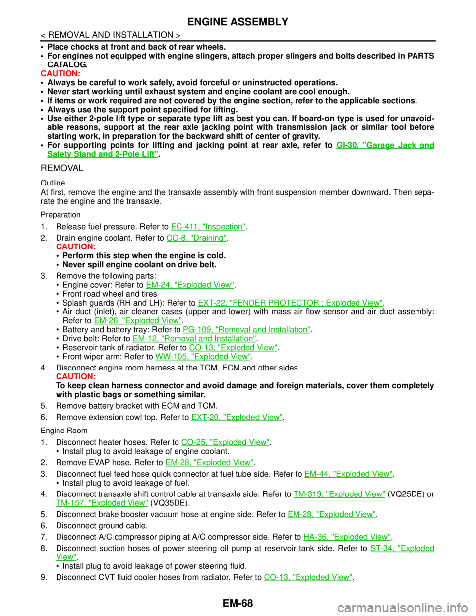
Place chocks at front and back of rear wheels.
For engines not equipped with engine slingers, attach proper slingers and bolts described in PARTS
CATALOG.
CAUTION:
Always be careful to work safely, avoid forceful or uninstructed operations.
Never start working until exhaust system and engine coolant are cool enough.
If items or work required are not covered by the engine section, refer to the applicable sections.
Always use the support point specified for lifting.
Use either 2-pole lift type or separate type lift as best you can. If board-on type is used for unavoid-
able reasons, support at the rear axle jacking point with transmission jack or similar tool before
starting work, in preparation for the backward shift of center of gravity.
For supporting points for lifting and jacking point at rear axle, refer to GI-30, "
Garage Jack and
Safety Stand and 2-Pole Lift".
REMOVAL
Outline
At first, remove the engine and the transaxle assembly with front suspension member downward. Then sepa-
rate the engine and the transaxle.
Preparation
1. Release fuel pressure. Refer to EC-411, "Inspection".
2. Drain engine coolant. Refer to CO-8, "
Draining".
CAUTION:
Perform this step when the engine is cold.
Never spill engine coolant on drive belt.
3. Remove the following parts:
Engine cover: Refer to EM-24, "
Exploded View".
Front road wheel and tires
Splash guards (RH and LH): Refer to EXT-22, "
FENDER PROTECTOR : Exploded View".
Air duct (inlet), air cleaner cases (upper and lower) with mass air flow sensor and air duct assembly:
Refer to EM-26, "
Exploded View".
Battery and battery tray: Refer to PG-109, "
Removal and Installation".
Drive belt: Refer to EM-12, "
Removal and Installation".
Reservoir tank of radiator. Refer to CO-13, "
Exploded View".
Front wiper arm: Refer to WW-105, "
Exploded View".
4. Disconnect engine room harness at the TCM, ECM and other sides.
CAUTION:
To keep clean harness connector and avoid damage and foreign materials, cover them completely
with plastic bags or something similar.
5. Remove battery bracket with ECM and TCM.
6. Remove extension cowl top. Refer to EXT-20, "
Exploded View".
Engine Room
1. Disconnect heater hoses. Refer to CO-25, "Exploded View".
Install plug to avoid leakage of engine coolant.
2. Remove EVAP hose. Refer to EM-28, "
Exploded View".
3. Disconnect fuel feed hose quick connector at fuel tube side. Refer to EM-44, "
Exploded View".
Install plug to avoid leakage of fuel.
4. Disconnect transaxle shift control cable at transaxle side. Refer to TM-319, "
Exploded View" (VQ25DE) or
TM-157, "
Exploded View" (VQ35DE).
5. Disconnect brake booster vacuum hose at engine side. Refer to EM-28, "
Exploded View".
6. Disconnect ground cable.
7. Disconnect A/C compressor piping at A/C compressor side. Refer to HA-36, "
Exploded View".
8. Disconnect suction hoses of power steering oil pump at reservoir tank side. Refer to ST-34, "
Exploded
View".
Install plug to avoid leakage of power steering fluid.
9. Disconnect CVT fluid cooler hoses from radiator. Refer to CO-13, "
Exploded View".
Page 3193 of 5121
GENERAL MAINTENANCE
MA-5
< ON-VEHICLE MAINTENANCE >
C
D
E
F
G
H
I
J
K
L
MB
MAN
OA
ON-VEHICLE MAINTENANCE
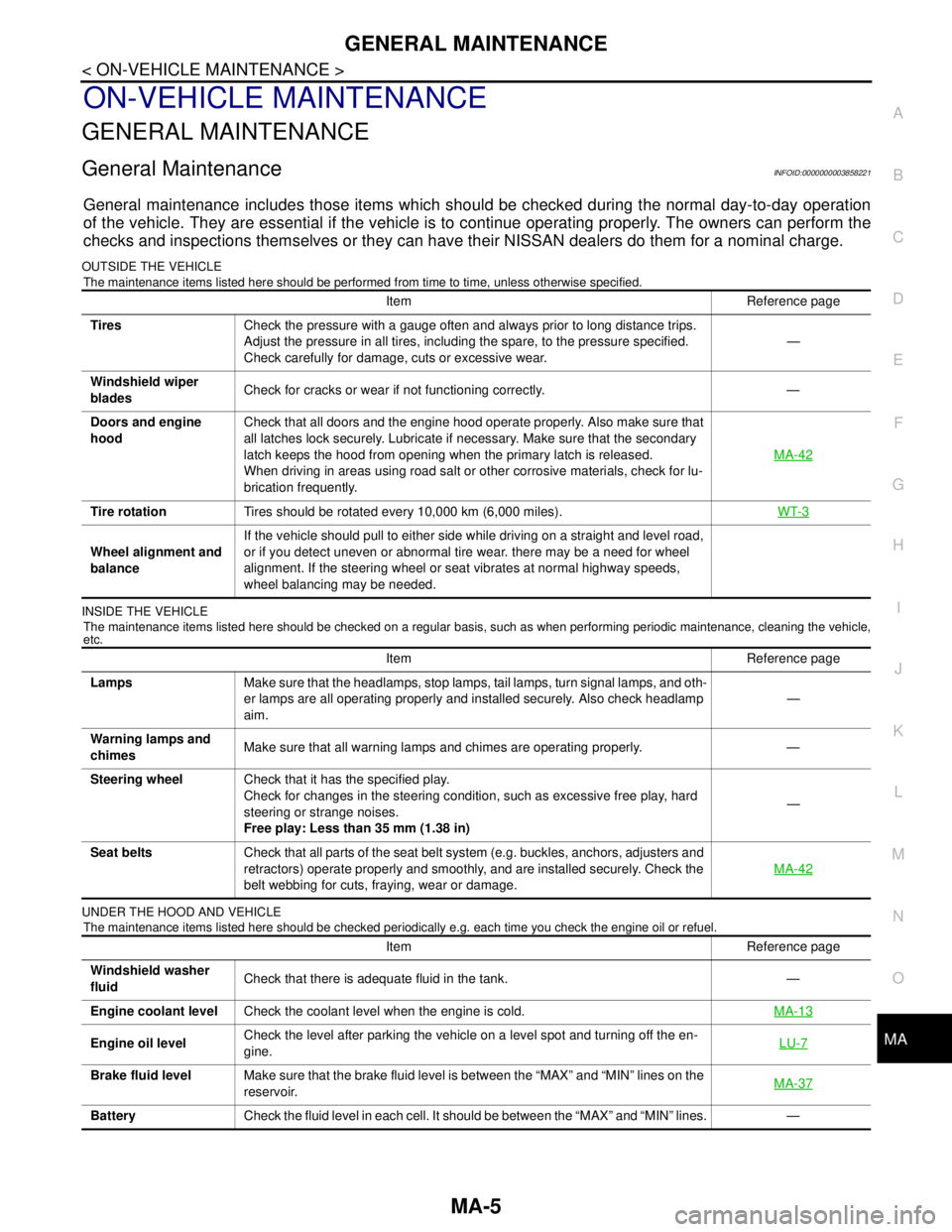
GENERAL MAINTENANCE
General MaintenanceINFOID:0000000003858221
General maintenance includes those items which should be checked during the normal day-to-day operation
of the vehicle. They are essential if the vehicle is to continue operating properly. The owners can perform the
checks and inspections themselves or they can have their NISSAN dealers do them for a nominal charge.
OUTSIDE THE VEHICLE
The maintenance items listed here should be performed from time to time, unless otherwise specified.
INSIDE THE VEHICLE
The maintenance items listed here should be checked on a regular basis, such as when performing periodic maintenance, cleaning the vehicle,
etc.
UNDER THE HOOD AND VEHICLE
The maintenance items listed here should be checked periodically e.g. each time you check the engine oil or refuel.
Item Reference page
TiresCheck the pressure with a gauge often and always prior to long distance trips.
Adjust the pressure in all tires, including the spare, to the pressure specified.
Check carefully for damage, cuts or excessive wear.—
Windshield wiper
bladesCheck for cracks or wear if not functioning correctly. —
Doors and engine
hoodCheck that all doors and the engine hood operate properly. Also make sure that
all latches lock securely. Lubricate if necessary. Make sure that the secondary
latch keeps the hood from opening when the primary latch is released.
When driving in areas using road salt or other corrosive materials, check for lu-
brication frequently.MA-42
Tire rotationTires should be rotated every 10,000 km (6,000 miles).WT-3
Wheel alignment and
balanceIf the vehicle should pull to either side while driving on a straight and level road,
or if you detect uneven or abnormal tire wear. there may be a need for wheel
alignment. If the steering wheel or seat vibrates at normal highway speeds,
wheel balancing may be needed.
Item Reference page
LampsMake sure that the headlamps, stop lamps, tail lamps, turn signal lamps, and oth-
er lamps are all operating properly and installed securely. Also check headlamp
aim.—
Warning lamps and
chimesMake sure that all warning lamps and chimes are operating properly. —
Steering wheelCheck that it has the specified play.
Check for changes in the steering condition, such as excessive free play, hard
steering or strange noises.
Free play: Less than 35 mm (1.38 in)—
Seat beltsCheck that all parts of the seat belt system (e.g. buckles, anchors, adjusters and
retractors) operate properly and smoothly, and are installed securely. Check the
belt webbing for cuts, fraying, wear or damage.MA-42
Item Reference page
Windshield washer
fluidCheck that there is adequate fluid in the tank. —
Engine coolant levelCheck the coolant level when the engine is cold.MA-13
Engine oil levelCheck the level after parking the vehicle on a level spot and turning off the en-
gine.LU-7
Brake fluid levelMake sure that the brake fluid level is between the “MAX” and “MIN” lines on the
reservoir.MA-37
BatteryCheck the fluid level in each cell. It should be between the “MAX” and “MIN” lines. —
Page 3199 of 5121

RECOMMENDED FLUIDS AND LUBRICANTS
MA-11
< ON-VEHICLE MAINTENANCE >
C
D
E
F
G
H
I
J
K
L
MB
MAN
OA
RECOMMENDED FLUIDS AND LUBRICANTS
Fluids and LubricantsINFOID:0000000003858223
*1: For further details, see “SAE Viscosity Number”.
*2: Use Genuine NISSAN Engine Coolant or equivalent in its quality, in order to avoid possible aluminum corrosion within the engine
cooling system caused by the use of non-genuine engine coolant.
Note that any repairs for the incidents within the engine cooling system while using non-genuine engine coolant may not be
covered by the warranty even if such incidents occurred during the warranty period.
*3: Using transmission fluid other than Genuine NISSAN CVT fluid NS-2 will damage the CVT, which is not covered by the war-
ranty.
*4: DEXRON
™ VI type ATF can be used.
*5: Never mix different types of fluids (DOT3 and DOT4).
SAE Viscosity NumberINFOID:0000000003858224
GASOLINE ENGINE
5W-30 is preferable.
Capacity (Approximate)
Recommended Fluids/Lubricants
LiterImp mea-
sure
Engine oil
Drain and refillWith oil filter change 4.6 4 qt
Genuine NISSAN engine oil
*1
API grade SL or SM*1
ILSAC grade GF-3 or GF-4*1
ACEA A1/B1, A3/B3, A3/B4, A5/B5, C2 or C3*1
Without oil filter
change4.3 3-3/4 qt
Dry engine (engine overhaul) 5.3 4-5/8 qt
Cooling system (with reservoir) 9.1 8 qt
Genuine NISSAN Engine Coolant or equivalent
in its quality
*2Reservoir tank 0.8 3/4 qt
CVT fluidRE0F10A 8.3 7-1/4 qt
Genuine NISSAN CVT Fluid NS-2
*3
RE0F09B 10.2 9 qt
Power steering fluid 1.0 7/8 qt
Genuine NISSAN PSF or equivalent
*4
Brake fluid — —Genuine NISSAN brake fluid, or equivalent DOT
3 or DOT4 (US FMVSS No. 116)*5
Multi-purpose grease — — NLGI No. 2 (Lithium soap base)
Page 3202 of 5121
MA-14
< ON-VEHICLE MAINTENANCE >
ENGINE MAINTENANCE
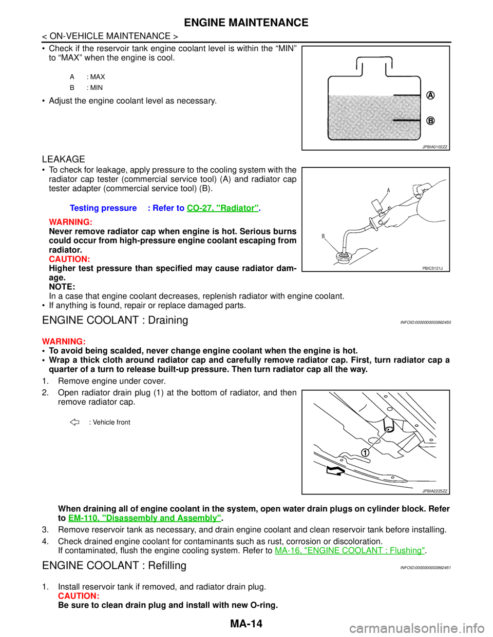
Check if the reservoir tank engine coolant level is within the “MIN”
to “MAX” when the engine is cool.
Adjust the engine coolant level as necessary.
LEAKAGE
To check for leakage, apply pressure to the cooling system with the
radiator cap tester (commercial service tool) (A) and radiator cap
tester adapter (commercial service tool) (B).
WARNING:
Never remove radiator cap when engine is hot. Serious burns
could occur from high-pressure engine coolant escaping from
radiator.
CAUTION:
Higher test pressure than specified may cause radiator dam-
age.
NOTE:
In a case that engine coolant decreases, replenish radiator with engine coolant.
If anything is found, repair or replace damaged parts.
ENGINE COOLANT : DrainingINFOID:0000000003862450
WARNING:
To avoid being scalded, never change engine coolant when the engine is hot.
Wrap a thick cloth around radiator cap and carefully remove radiator cap. First, turn radiator cap a
quarter of a turn to release built-up pressure. Then turn radiator cap all the way.
1. Remove engine under cover.
2. Open radiator drain plug (1) at the bottom of radiator, and then
remove radiator cap.
When draining all of engine coolant in the system, open water drain plugs on cylinder block. Refer
to EM-110, "
Disassembly and Assembly".
3. Remove reservoir tank as necessary, and drain engine coolant and clean reservoir tank before installing.
4. Check drained engine coolant for contaminants such as rust, corrosion or discoloration.
If contaminated, flush the engine cooling system. Refer to MA-16, "
ENGINE COOLANT : Flushing".
ENGINE COOLANT : RefillingINFOID:0000000003862451
1. Install reservoir tank if removed, and radiator drain plug.
CAUTION:
Be sure to clean drain plug and install with new O-ring.
A: MAX
B: MIN
JPBIA0102ZZ
Testing pressure : Refer to CO-27, "Radiator".
PBIC5121J
: Vehicle front
JPBIA2225ZZ
Page 3203 of 5121
ENGINE MAINTENANCE
MA-15
< ON-VEHICLE MAINTENANCE >
C
D
E
F
G
H
I
J
K
L
MB
MAN
OA
If water drain plugs on cylinder block are removed, close and tighten them. Refer to EM-110, "Dis-
assembly and Assembly".
2. Check that each hose clamp has been firmly tightened.
3. Remove air duct assembly and air cleaner cases (upper and lower) assembly. Refer to EM-26, "
Exploded
View".
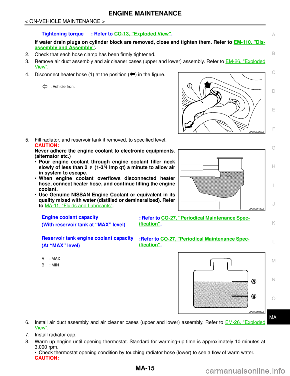
4. Disconnect heater hose (1) at the position ( ) in the figure.
5. Fill radiator, and reservoir tank if removed, to specified level.
CAUTION:
Never adhere the engine coolant to electronic equipments.
(alternator etc.)
Pour engine coolant through engine coolant filler neck
slowly of less than 2 (1-3/4 lmp qt) a minute to allow air
in system to escape.
When engine coolant overflows disconnected heater
hose, connect heater hose, and continue filling the engine
coolant.
Use Genuine NISSAN Engine Coolant or equivalent in its
quality mixed with water (distilled or demineralized). Refer
to MA-11, "
Fluids and Lubricants".
6. Install air duct assembly and air cleaner cases (upper and lower) assembly. Refer to EM-26, "
Exploded
View".
7. Install radiator cap.
8. Warm up engine until opening thermostat. Standard for warming-up time is approximately 10 minutes at
3,000 rpm.
Check thermostat opening condition by touching radiator hose (lower) to see a flow of warm water.
CAUTION:Tightening torque : Refer to CO-13, "
Exploded View".
: Vehicle front
JPBIA2226ZZ
Engine coolant capacity
: Refer to CO-27, "Periodical Maintenance Spec-
ification".
(With reservoir tank at “MAX” level)
Reservoir tank engine coolant capacity
:Refer to CO-27, "
Periodical Maintenance Spec-
ification".
(At “MAX” level)
A : MAX
B: MIN
JPBIA0412ZZ
JPBIA0102ZZ