2008 NISSAN LATIO sensor
[x] Cancel search: sensorPage 2676 of 2771

SRS-42
< ON-VEHICLE REPAIR >
SIDE AIR BAG (SATELLITE) SENSOR
SIDE AIR BAG (SATELLITE) SENSOR
Removal and InstallationINFOID:0000000001703932
REMOVAL
WARNING:
Do not reuse center pillar upper garnish if removed.
CAUTION:
• Before servicing the SRS, turn ignition switch OFF, disconnect both battery cables and wait at least
3 minutes.
• Do not disassemble the side air bag (satellite) sensor.
• Do not use old nuts after removal; replace with new nuts.
• Replace the side air bag (satellite) sensor if it has been
dropped or sustained an impact.
• Check side air bag (satellite) sensor to make sure it is free of
deformities, dents, cracks or rust. If it shows any visible signs
of damage, replace it with a new one.
1. Disconnect both the negative and positive battery cables, then wait at least 3 minutes.
2. Remove the front seat belt retractor. Refer to SB-3, "
Removal and Installation of Front Seat Belt".
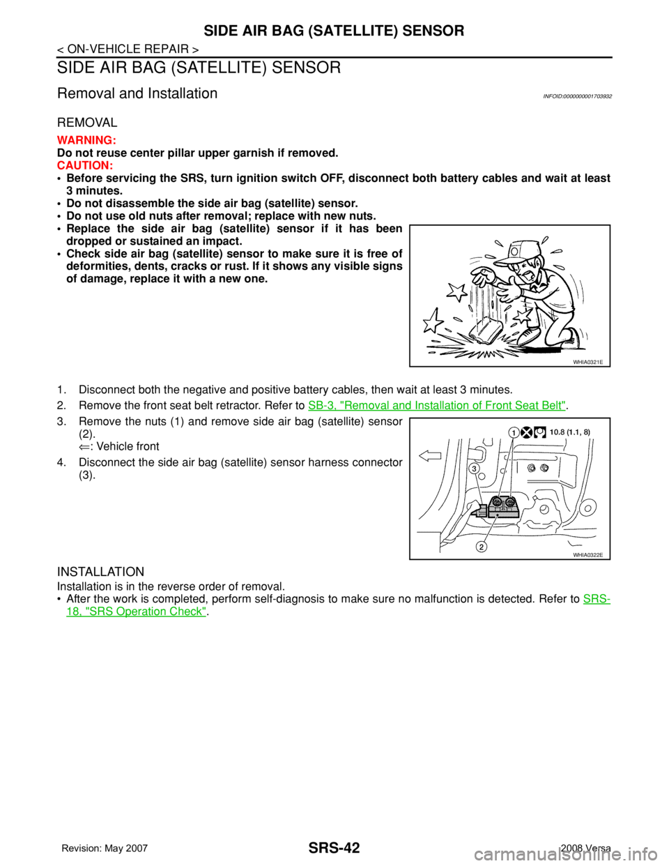
3. Remove the nuts (1) and remove side air bag (satellite) sensor
(2).
⇐: Vehicle front
4. Disconnect the side air bag (satellite) sensor harness connector
(3).
INSTALLATION
Installation is in the reverse order of removal.
• After the work is completed, perform self-diagnosis to make sure no malfunction is detected. Refer to SRS-
18, "SRS Operation Check".
WHIA0321E
WHIA0322E
Page 2678 of 2771

SRS-44
< ON-VEHICLE REPAIR >
DIAGNOSIS SENSOR UNIT
DIAGNOSIS SENSOR UNIT
Removal and InstallationINFOID:0000000001703934
REMOVAL
WARNING:
Before disconnecting diagnosis sensor unit harness connector(s), be sure to disconnect harness con-
nectors from air bag modules and front seat belt pre-tensioner to prevent deployment by static elec-
tricity.
CAUTION:
• Before servicing the SRS, turn the ignition switch OFF, disconnect both battery cables and wait at
least 3 minutes.
• Do not disassemble diagnosis sensor unit.
• Do not use old bolts; replace with new bolts.
• Replace the diagnosis sensor unit if it has been dropped or sustained an impact.
• Check diagnosis sensor unit bracket to make sure it is free of deformities, dents, cracks or rust. If it
shows any visible signs of damage, replace with new one.
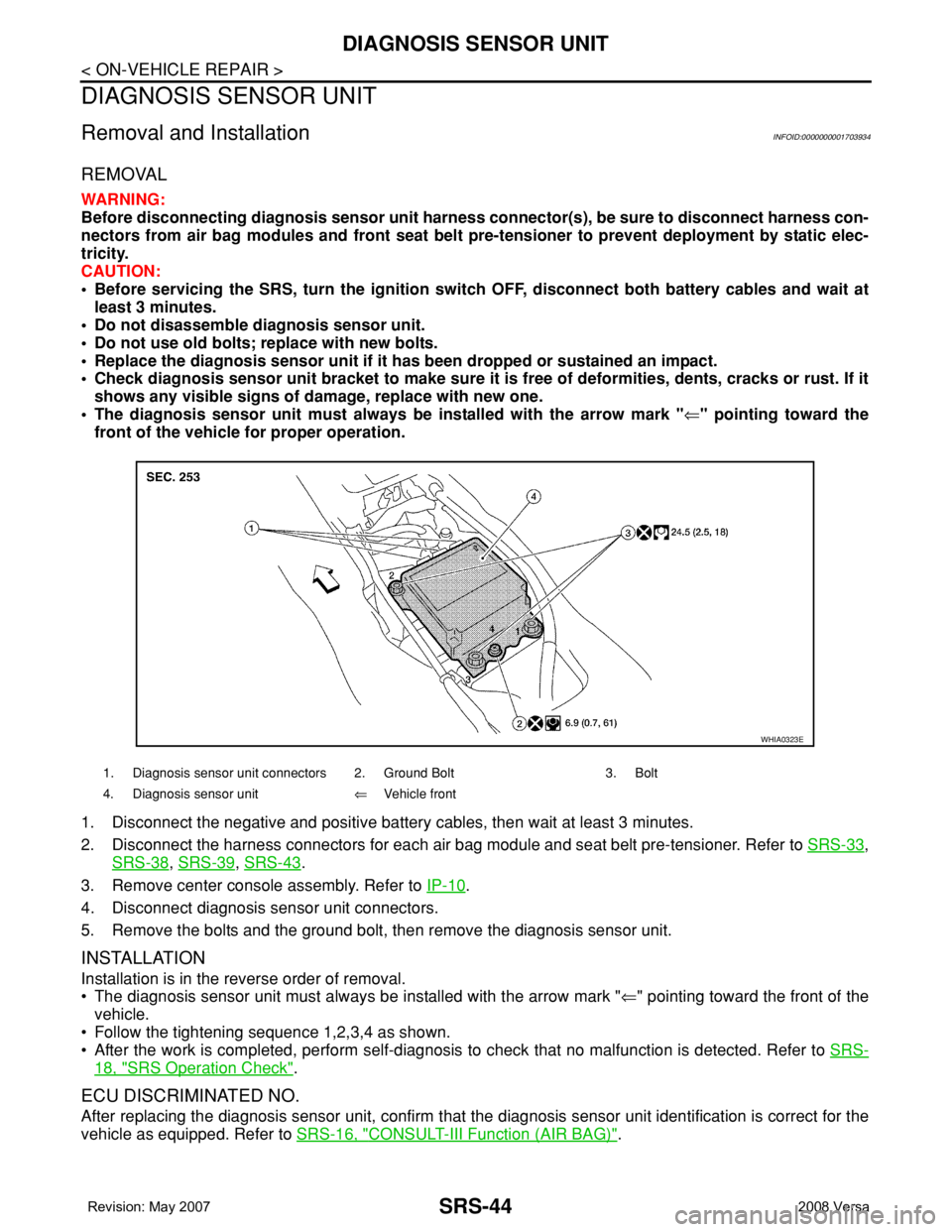
• The diagnosis sensor unit must always be installed with the arrow mark "⇐" pointing toward the
front of the vehicle for proper operation.
1. Disconnect the negative and positive battery cables, then wait at least 3 minutes.
2. Disconnect the harness connectors for each air bag module and seat belt pre-tensioner. Refer to SRS-33
,
SRS-38
, SRS-39, SRS-43.
3. Remove center console assembly. Refer to IP-10
.
4. Disconnect diagnosis sensor unit connectors.
5. Remove the bolts and the ground bolt, then remove the diagnosis sensor unit.
INSTALLATION
Installation is in the reverse order of removal.
• The diagnosis sensor unit must always be installed with the arrow mark "⇐" pointing toward the front of the
vehicle.
• Follow the tightening sequence 1,2,3,4 as shown.
• After the work is completed, perform self-diagnosis to check that no malfunction is detected. Refer to SRS-
18, "SRS Operation Check".
ECU DISCRIMINATED NO.
After replacing the diagnosis sensor unit, confirm that the diagnosis sensor unit identification is correct for the
vehicle as equipped. Refer to SRS-16, "
CONSULT-III Function (AIR BAG)".
1. Diagnosis sensor unit connectors 2. Ground Bolt 3. Bolt
4. Diagnosis sensor unit⇐Vehicle front
WHIA0323E
Page 2679 of 2771

OCCUPANT CLASSIFICATION SYSTEM CONTROL UNIT
SRS-45
< ON-VEHICLE REPAIR >
C
D
E
F
G
I
J
K
L
MA
B
SRS
N
O
P
OCCUPANT CLASSIFICATION SYSTEM CONTROL UNIT
Removal and InstallationINFOID:0000000001703935
The occupant classification system control unit, occupant classification system sensor, and bladder are an
integral part of the front passenger seat cushion and are replaced as an assembly. Refer to SE-10
to remove
the seat, and SE-12, "
Disassembly and Assembly" to replace the seat cushion.
Page 2680 of 2771

SRS-46
< ON-VEHICLE REPAIR >
COLLISION DIAGNOSIS
COLLISION DIAGNOSIS
For Frontal CollisionINFOID:0000000001703936
Check the SRS components using the following table.
• After the work is completed, perform self-diagnosis to check that no malfunction is detected. Refer to SRS-
18, "SRS Operation Check".
SRS INSPECTION (FOR FRONTAL COLLISION)
Part SRS is activated SRS is NOT activated
Driver air bag module If the driver air bag
has deployed:
REPLACE
Install with new fas-
teners.If the driver air bag has NOT been activated:
1. Remove driver air bag module. Check harness cover and connectors for dam-
age, terminals for deformities, and harness for binding.
2. Install driver air bag module into the steering wheel to check fit and alignment
with the wheel.
3. If no damage is found, reinstall with new fasteners.
4. If damaged—REPLACE. Install driver air bag modules with new fasteners.
Front passenger air
bag moduleIf the front passenger
air bag has deployed:
REPLACE
Install with new fas-
teners.If the front passenger air bag has NOT been activated:
1. Remove front passenger air bag module. Check harness cover and connectors
for damage, terminals for deformities, and harness for binding.
2. Install front passenger air bag module into the instrument panel to check fit with
the instrument panel.
3. If no damage is found, reinstall with new fasteners.
4. If damaged—REPLACE. Install front passenger air bag modules with new fas-
teners.
Crash zone sensor If any of the front air
bags or seat belt pre-
tensioners* have
been activated:
REPLACE the crash
zone sensor and
bracket with new fas-
teners.
*: Confirm seat belt
pre-tensioner activa-
tion using CONSULT-
III only.If the front air bags or seat belt pre-tensioners have NOT been activated:
1. Remove the crash zone sensor. Check harness connectors for damage, termi-
nals for deformities, and harness for binding.
2. Check for visible signs of damage (dents, cracks, deformation) of the crash zone
sensor and bracket.
3. Install the crash zone sensor to check fit.
4. If no damage is found, reinstall with new fasteners.
5. If damaged—REPLACE the crash zone sensor and bracket with new fasteners.
Seat belt pre-tension-
er assemblies
(All applicable loca-
tions: buckle, reel, lap
outer)If either the driver or
passenger seat belt
pre-tensioner* has
been activated:
REPLACE all seat
belt pre-tensioner as-
semblies with new
fasteners.
*: Confirm seat belt
pre-tensioner activa-
tion using CONSULT-
III only.If the pre-tensioners have NOT been activated:
1. Remove seat belt pre-tensioners.
Check harness cover and connectors for damage, terminals for deformities, and
harness for binding.
2. Check belts for damage and anchors for loose mounting.
3. Check retractor for smooth operation.
4. Check seat belt adjuster for damage.
5. Check for deformities of the center pillar inner.
6. If the center pillar inner has no damage, REPLACE the seat belt pre-tensioner
assembly.
7. If no damage is found, reinstall seat belt pre-tensioner assembly.
8. If damaged—REPLACE. Install the seat belt pre-tensioners with new fasteners.
Diagnosis sensor unit If any of the SRS com-
ponents have been
activated:
REPLACE the diag-
nosis sensor unit.
Install with new fas-
teners.If none of the SRS components have been activated:
1. Check case for dents, cracks or deformities.
2. Check connectors for damage, and terminals for deformities.
3. If no damage is found, reinstall with new fasteners.
4. If damaged—REPLACE. Install diagnosis sensor unit with new fasteners.
Page 2681 of 2771

COLLISION DIAGNOSIS
SRS-47
< ON-VEHICLE REPAIR >
C
D
E
F
G
I
J
K
L
MA
B
SRS
N
O
P
For Side and Rollover CollisionINFOID:0000000001703937
Check the SRS components using the following table.
• After the work is completed, perform self-diagnosis to check that no malfunction is detected. Refer to SRS-
18, "SRS Operation Check".
WHEN SRS IS ACTIVATED IN THE SIDE OR ROLLOVER COLLISION
1. Replace the following components:
- Front seat back assembly (on the side on which side air bag is activated)
- Diagnosis sensor unit
- (LH or RH) side air bag (satellite) sensor (on the side on which side air bag is activated)
2. Check the SRS components and the related parts using the following table.
- Replace any SRS components and the related parts showing visible signs of damage (dents, cracks,
deformation).
3. Conduct self-diagnosis using CONSULT-III and “AIR BAG” warning lamp. Refer to SRS-18, "
SRS Opera-
tion Check" for details. Ensure entire SRS operates properly.
WHEN SRS IS NOT ACTIVATED IN THE SIDE OR ROLLOVER COLLISION
1. Check the SRS components and the related parts using the following table.
- If the front seat back assembly is damaged, the front seat back assembly must be replaced.
2. Conduct self-diagnosis using CONSULT-III and “AIR BAG” warning lamp. Refer to SRS-18, "
SRS Opera-
tion Check" for details. Ensure entire SRS operates properly.
SRS INSPECTION (FOR SIDE AND ROLLOVER COLLISION)
Steering wheel 1. Visually check steering wheel for deformities.
2. Check harness (built into steering wheel) and connectors for damage, and terminals for deformities.
3. Install driver air bag module into the steering wheel to check fit and alignment with the wheel.
4. Check steering wheel for excessive free play.
5. If no damage is found, reinstall.
6. If damaged—REPLACE.
Spiral cable If the driver front air
bag has deployed:
REPLACE the spiral
cable.If the driver front air bag has not deployed:
1. Visually check spiral cable and combination switch for damage.
2. Check connectors and protective tape for damage.
3. Check steering wheel for noise, binding or heavy operation.
4. If no damage is found, reinstall.
5. If damaged—REPLACE.
Occupant classifica-
tion system (Passen-
ger seat)1. Remove passenger seat.
2. Check control unit case for dents, cracks of deformities.
3. Check connectors and pressure sensor tube for damage, and terminals for deformities.
4. Check seat frame and cushion pan for dents or deformities.
5. If no damage is found, reinstall seat with new fasteners.
6. If damaged — REPLACE seat cushion assembly with new fasteners.
Harness and connec-
tors1. Check connectors for poor connection, damage, and terminals for deformities.
2. Check harness for binding, chafing, cuts, or deformities.
3. If no damage is found, reinstall the harness and connectors.
4. If damaged—REPLACE the damaged harness. Do not attempt to repair, splice or modify any SRS har-
ness.
Instrument panel If the passenger front
air bag has deployed:
REPLACE the instru-
ment panel assembly.If the passenger front air bag has NOT deployed:
1. Visually check instrument panel for damage.
2. If no damage is found, reinstall the instrument panel.
3. If damaged—REPLACE the instrument panel. Part SRS is activated SRS is NOT activated
Page 2682 of 2771

SRS-48
< ON-VEHICLE REPAIR >
COLLISION DIAGNOSIS
Part SRS is activated SRS is NOT activated
LH side curtain air
bag moduleIf the LH side curtain
air bag has deployed:
REPLACE the LH
side curtain air bag
module. (Repair the
center pillar inner, etc.
before installing new
one if damaged.)If the LH side curtain air bag has NOT deployed:
1. Check for visible signs of damage (dents, tears, deformation) of the center pillar
on the collision side.
2. If damaged—Remove the LH side curtain air bag module.
3. Check for visible signs of damaged (tears etc.) of the LH side curtain air bag mod-
ule.
4. Check harness and connectors for damage, and terminals for deformities.
5. If no damage is found, reinstall the LH side curtain air bag module with new fas-
teners.
6. If damaged—REPLACE the LH side curtain air bag module with new fasteners.
RH side curtain air
bag moduleIf the RH side curtain
air bag has deployed:
REPLACE the RH
side curtain air bag
module. (Repair the
center pillar inner, etc.
before installing new
one if damaged.)If the RH side curtain air bag has NOT deployed:
1. Check for visible signs of damage (dents, tears, deformation) of the center pillar
on the collision side.
2. If damaged—Remove the RH side curtain air bag module.
3. Check for visible signs of damaged (tears etc.) of the RH side curtain air bag
module.
4. Check harness and connectors for damage, and terminals for deformities.
5. If no damage is found, reinstall the RH side curtain air bag module with new fas-
teners.
6. If damaged—REPLACE the RH side curtain air bag module with new fasteners.
Front LH side air bag
moduleIf the front LH side air
bag has deployed:
REPLACE front LH
seatback assembly.If the front LH side air bag has NOT deployed:
1. Check for visible signs of damage (dents, tears, deformation) of the seat back on
the collision side.
2. Check harness and connectors for damage, and terminals for deformities.
3. If damaged—REPLACE the front LH seatback assembly.
Front RH side air bag
moduleIf the front RH side air
bag has deployed:
REPLACE front RH
seatback assembly.If the front RH side air bag has NOT deployed:
1. Check for visible signs of damage (dents, tears, deformation) of the seat back on
the collision side.
2. Check harness and connectors for damage, and terminals for deformities.
3. If damaged—REPLACE the front RH seatback assembly.
(LH or RH) side air
bag (satellite) sensor If any of the SRS
components have de-
ployed:
REPLACE the side air
bag (satellite) sensor
on the collision side
with new fasteners.
(Repair the center pil-
lar inner, etc. before
installing new one if
damaged.)If none of the SRS components have been activated:
1. Remove the side air bag (satellite) sensor on the collision side. Check harness
connectors for damage, terminals for deformities, and harness for binding.
2. Check for visible signs of damage (dents, cracks, deformation) of the side air bag
(satellite) sensor.
3. Install the side air bag (satellite) sensor to check fit.
4. If no damage is found, reinstall the side sir bag (satellite) sensor with new fasten-
ers.
5. If damaged—REPLACE the side air bag (satellite) sensor with new fasteners.
Diagnosis sensor unit If any of the SRS
components have de-
ployed:
REPLACE the diag-
nosis sensor unit with
new fasteners.If none of the SRS components have been activated:
1. Check case and bracket for dents, cracks or deformities.
2. Check connectors for damage, and terminals for deformities.
3. If no damage is found, reinstall the diagnosis sensor unit with new fasteners.
4. If damaged—REPLACE the diagnosis sensor unit with new fasteners.
Seat belt pre-tension-
er assemblies
(All applicable loca-
tions: buckle, reel, lap
outer)If either the driver or
passenger seat belt
pre-tensioner* has
been activated:
REPLACE all seat
belt pre-tensioner as-
semblies with new
fasteners.
*: Confirm seat belt
pre-tensioner activa-
tion using CONSULT-
III only.If the pre-tensioners have NOT been activated:
1. Remove seat belt pre-tensioners.
Check harness cover and connectors for damage, terminals for deformities, and
harness for binding.
2. Check belts for damage and anchors for loose mounting.
3. Check retractor for smooth operation.
4. Check seat belt adjuster for damage.
5. Check for deformities of the center pillar inner.
6. If the center pillar inner has no damage, REPLACE the seat belt pre-tensioner
assembly.
7. If no damage is found, reinstall seat belt pre-tensioner assembly.
8. If damaged—REPLACE. Install the seat belt pre-tensioners with new fasteners.
Page 2684 of 2771

STC-1
STEERING
C
D
E
F
H
I
J
K
L
M
SECTION STC
A
B
STC
N
O
P
CONTENTS
STEERING CONTROL SYSTEM
EPS
SERVICE INFORMATION ............................
2
PRECAUTIONS ...................................................2
Precaution for Supplemental Restraint System
(SRS) "AIR BAG" and "SEAT BELT PRE-TEN-
SIONER" ...................................................................
2
Precaution Necessary for Steering Wheel Rota-
tion After Battery Disconnect .....................................
2
Service Notice or Precaution for EPS System ..........2
EPS SYSTEM ......................................................4
System Description ...................................................4
Schematic .................................................................5
CAN Communication .................................................5
TROUBLE DIAGNOSIS ......................................6
Fail-Safe Function .....................................................6
How to Perform Trouble Diagnosis ...........................6
Component Parts Location ........................................7
Wiring Diagram - EPS - .............................................8
EPS Control Unit Input/Output Signal Reference
Value .........................................................................
9
EPS Terminal and Reference Value ........................10
CONSULT-III Function (EPS) ..................................11
Symptom Chart ........................................................13
TROUBLE DIAGNOSIS FOR SYSTEM ............14
DTC C1601 BATTERY VOLT ..................................14
DTC C1604 TORQUE SENSOR .............................15
DTC C1606 EPS MOTOR .......................................16
DTC C1607 EEPROM .............................................17
DTC C1608 CONTROL UNIT ..................................17
DTC C1609 CAN VHCL SPEED .............................18
DTC C1610 CAN ENG RPM ...................................19
DTC U1000 CAN COMM CIRCUIT .........................19
Component Inspection .............................................19
TROUBLE DIAGNOSIS FOR SYMPTOMS ......21
EPS Warning Lamp Does Not Turn ON ..................21
EPS Warning Lamp Does Not Turn OFF ................21
Steering Wheel Turning Force Is Heavy or Light .....22
Unbalance Steering Wheel Turning Force and Re-
turn Between Right and Left ....................................
23
Unbalance Steering Wheel Turning Force (Torque
Variation) .................................................................
24
Page 2687 of 2771
![NISSAN LATIO 2008 Service Repair Manual STC-4
< SERVICE INFORMATION >[EPS]
EPS SYSTEM
EPS SYSTEM
System DescriptionINFOID:0000000001703872
EPS CONTROL UNIT
• EPS control unit performs an arithmetical operation on data, such
as steering wh NISSAN LATIO 2008 Service Repair Manual STC-4
< SERVICE INFORMATION >[EPS]
EPS SYSTEM
EPS SYSTEM
System DescriptionINFOID:0000000001703872
EPS CONTROL UNIT
• EPS control unit performs an arithmetical operation on data, such
as steering wh](/manual-img/5/57360/w960_57360-2686.png)
STC-4
< SERVICE INFORMATION >[EPS]
EPS SYSTEM
EPS SYSTEM
System DescriptionINFOID:0000000001703872
EPS CONTROL UNIT
• EPS control unit performs an arithmetical operation on data, such
as steering wheel turning force (sensor signal) from the torque
sensor, vehicle speed signal, etc. Then it generates an optimum
assist torque to the EPS motor according to the driving condition.
• EPS control unit decreases the output to EPS motor while
extremely using the power steering function (e.g., full steering) for
protecting EPS motor and EPS control unit (Protect overload sta-
tus). While activating protect overload status, the assist torque
gradually decreases, and the steering wheel turning force
becomes heavy. The normal assist torque reactivates by not steer-
ing.
• In case of an error in the electrical system, the fail-safe function
stops output signals to the EPS motor. Then the previous state is changed to the manual steering state.
• Self-diagnosis can be done with CONSULT-III.
EPS MOTOR
EPS motor provides the assist torque by control signal from EPS control unit.
TORQUE SENSOR
Torque sensor detects the steering torque, and transmit the signal to
EPS control unit.
REDUCTION GEAR
Reduction gear increases the assist torque provided from EPS motor with worm gears, and outputs to the col-
umn shaft.
EPS WARNING LAMP
Turns ON when there is a malfunction in EPS system. It indicates that fail-safe mode is engaged and enters a
manual steering state (Control turning force steering wheel becomes heavy).
Also turns ON when ignition switch is turned ON, for purpose of lamp check. Turns OFF after the engine starts
if system is normal.
EPS Warning Lamp Indication
SGIA1647E
SGIA1648E
Condition EPS warning lamp
Lamp checkTurns ON when ignition switch is turned ON.
Turns OFF after engine start.
EPS system malfunctionON
Other than above (system normal) OFF