2008 NISSAN LATIO sensor
[x] Cancel search: sensorPage 2491 of 2771

PG-58
< SERVICE INFORMATION >
HARNESS
Wiring Diagram Codes (Cell Codes)
INFOID:0000000001704709
Use the chart below to find out what each wiring diagram code stands for.
Refer to the wiring diagram code in the alphabetical index to find the location (page number) of each wiring
diagram.
D3 D404 W/3 : Rear wiper motor
D4 D405 W/4 : Back door lock assembly
D4 D406 W/2 : Back door request switch
E2 D407 W/2 : High mounted stop lamp
D4 D408 BR/2 : Back door opener switch
E4 D409 B/1 : Condenser-1
C2 D410 — : Body ground
E3 D411 B/1 : Condenser-1
E1 D412 B/1 : Rear window defogger (+)
C2 D413 B/1 : Rear window defogger (-)
F3 D414 — : Body ground
Code Section Wiring Diagram Name
ABS BRC Anti-lock Brake System
A/C,M MTC Manual Air Conditioner
APPS1 EC Accelerator Pedal Position Sensor
A/F EC Air Fuel Ratio Sensor 1
A/FH EC Air Fuel Ratio Sensor 1 Heater
APPS2 EC Accelerator Pedal Position Sensor
APPS3 EC Accelerator Pedal Position Sensor
ASC/BS EC ASCD Brake Switch
ASC/SW EC ASCD Steering Switch
ASCBOF EC ASCD Brake Switch
ASCIND EC ASCD Indicator
AT/IND DI A/T Indicator Lamp
AUDIO AV Audio
BACK/L LT Back-up Lamp
BA/FTS AT A/T Fluid Temperature Sensor and TCM Power Supply
B/DOOR BL Back Door Opener
BRK/SW EC Brake Switch
CAN AT CAN Communication Line
CAN CVT CAN Communication Line
CAN EC CAN Communication Line
CAN LAN CAN System
CHARGE SC Charging System
CHIME DI Warning Chime
COOL/F EC Cooling Fan Control
COMBSW LT Combination Switch
CVTIND DI CVT Indicator Lamp
D/LOCK BL Power Door Lock
DEF GW Rear Window Defogger
DTRL LT Headlamp - With Daytime Light System
ECTS EC Engine Coolant Temperature Sensor
ENGSS AT Engine Speed Signal
EPS STC Electronic Controlled Power Steering
ETC1 EC Electric Throttle Control Function
Page 2492 of 2771

HARNESS
PG-59
< SERVICE INFORMATION >
C
D
E
F
G
H
I
J
L
MA
B
PG
N
O
P
ETC2 EC Throttle Control Motor Relay
ETC3 EC Throttle Control Motor
F/FOG LT Front Fog Lamp
F/PUMP EC Fuel Pump
FTS AT A/T Fluid Temperature Sensor
FTS CVT CVT Fluid Temperature Sensor Circuit
FTTS EC Fuel Tank Temperature Sensor
FUEL EC Fuel Ignition System Function
HEATER MTC Heater System
H/LAMP LT Headlamp
H/PHON AV Hands Free Telephone
HORN WW Horn
HO2S2 EC Heated Oxygen Sensor 2
HO2S2H EC Heated Oxygen Sensor 2 Heater
IATS EC Intake Air Temperature Sensor
IGNSYS EC Ignition System
I/KEY BL Intelligent Key System
ILL LT Illumination
INJECT EC Injector
INT/L LT Room/Map, Vanity and Luggage Lamps
IVC EC Intake Valve Timing Control Solenoid Valve
KEYLES BL Remote Keyless Entry System
KS EC Knock Sensor
LPSV AT Line Pressure Solenoid Valve
LPSV CVT Line Pressure Solenoid Valve
L/USSV CVT Lock-up Select Solenoid Valve
MAFS EC Mass Air Flow Sensor
MAIN AT Main Power Supply and Ground Circuit
MAIN EC Main Power Supply and Ground Circuit
METER DI Speedometer, Tachometer, Temp. and Fuel Gauges
MIL/DL EC Malfunction Indicator Lamp
MIRROR GW Door Mirror
NATS BL Nissan Anti-Theft System
NONDTC AT Non-detectable Item
NONDTC CVT Non-detectable Item
ODSW CVT Overdrive Control Switch
OVRCSV AT Over Run Clutch Solenoid Valve
P/SCKT WW Power Socket
PGC/V EC EVAP Canister Purge Volume Control Solenoid Valve
PHASE EC Camshaft Position Sensor (PHASE)
PNP/SW AT Park/Neutral Position Switch
PNP/SW CVT Park/Neutral Position Switch
PNP/SW EC Park/Neutral Position Switch
POS EC Crankshaft Position Sensor (POS)
POWER CVT Transmission Control Module (Power Supply)
PRE/SE EC EVAP Control System Pressure Sensor
PRIPS CVT Primary Pressure Sensor
PRSCVT CVT Primary Speed Sensor CVT (Revolution Sensor)
PT/SEN AT Powertrain Revolution Sensor
RP/SEN EC Refrigerant Pressure Sensor
SECPS CVT Secondary Pressure Sensor
SECPSV CVT Secondary Speed Sensor CVT (Revolution Sensor)
Page 2493 of 2771

PG-60
< SERVICE INFORMATION >
HARNESS
SEN/PW EC Sensor Power Supply
SESCVT CVT Secondary Pressure Sensor Solenoid Valve
SHIFT AT A/T Shift Lock System
SHIFT CVT CVT Shift Lock System
SROOF RF Sunroof
SRS SRS Supplemental Restraint System
SSV/A AT Shift Solenoid Valve A
SSV/B AT Shift Solenoid Valve B
START SC Starting System
STM CVT Step Motor
STSIG CVT Start Signal Circuit
STOP/L LT Stop Lamp
TCV AT Torque Converter Clutch Solenoid Valve
TCV CVT Torque Converter Clutch Solenoid Valve
T/LID BL Trunk Lid Opener
T/WARN WT Low Tire Pressure Warning System
TAIL/L LT Parking, License and Tail Lamps
TPS1 EC Throttle Position Sensor
TPS2 EC Throttle Position Sensor
TPS3 EC Throttle Position Sensor
TURN LT Turn Signal and Hazard Warning Lamps
VEHSEC BL Vehicle Security (Theft Warning) System
VENT/V EC EVAP Canister Vent Control Valve
VSSA/T AT Vehicle Speed Sensor A/T (Revolution Sensor)
VSSMTR AT Vehicle Speed Sensor MTR
WARN DI Warning Lamps
WINDOW GW Power Window
WIP/R WW Rear Wiper and Washer
WIPER WW Front Wiper and Washer
Page 2515 of 2771
STEERING COLUMN
PS-9
< SERVICE INFORMATION >
C
D
E
F
H
I
J
K
L
MA
B
PS
N
O
P
STEERING COLUMN
Removal and InstallationINFOID:0000000001703861
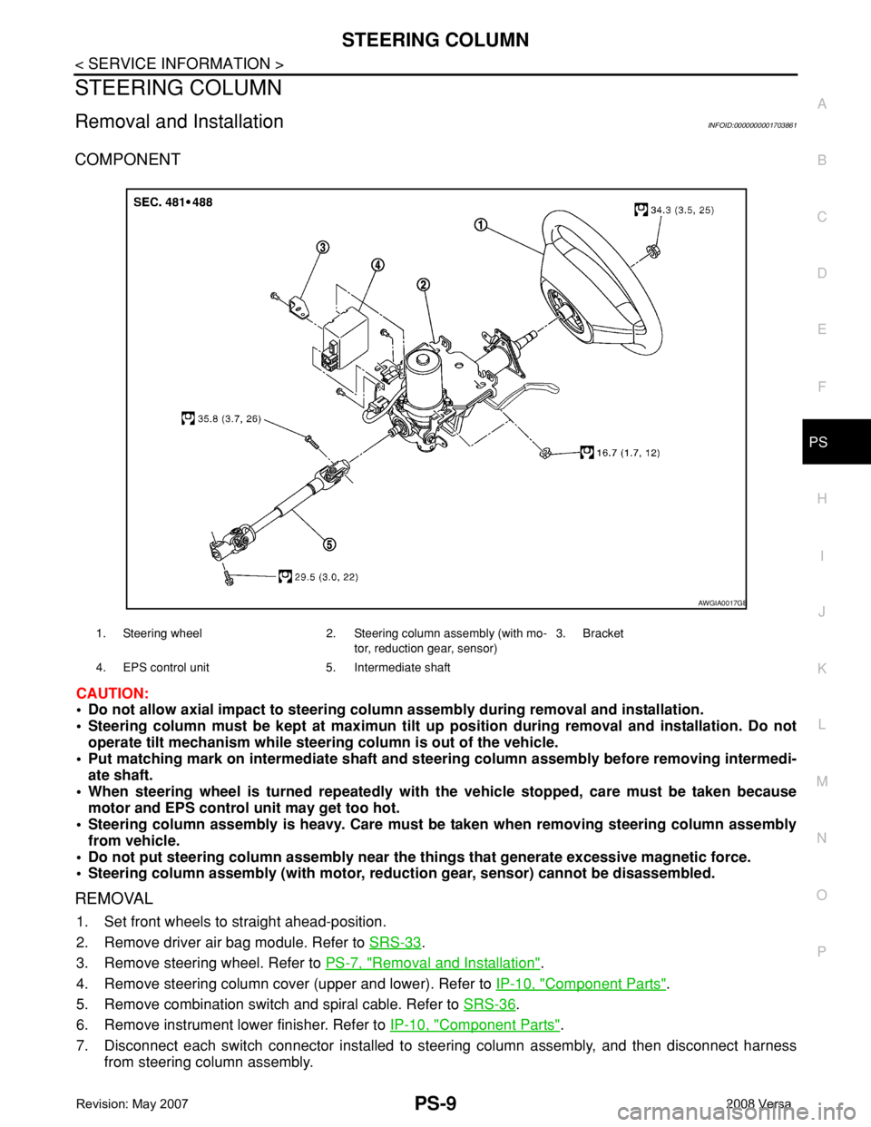
COMPONENT
CAUTION:
• Do not allow axial impact to steering column assembly during removal and installation.
• Steering column must be kept at maximun tilt up position during removal and installation. Do not
operate tilt mechanism while steering column is out of the vehicle.
• Put matching mark on intermediate shaft and steering column assembly before removing intermedi-
ate shaft.
• When steering wheel is turned repeatedly with the vehicle stopped, care must be taken because
motor and EPS control unit may get too hot.
• Steering column assembly is heavy. Care must be taken when removing steering column assembly
from vehicle.
• Do not put steering column assembly near the things that generate excessive magnetic force.
• Steering column assembly (with motor, reduction gear, sensor) cannot be disassembled.
REMOVAL
1. Set front wheels to straight ahead-position.
2. Remove driver air bag module. Refer to SRS-33
.
3. Remove steering wheel. Refer to PS-7, "
Removal and Installation".
4. Remove steering column cover (upper and lower). Refer to IP-10, "
Component Parts".
5. Remove combination switch and spiral cable. Refer to SRS-36
.
6. Remove instrument lower finisher. Refer to IP-10, "
Component Parts".
7. Disconnect each switch connector installed to steering column assembly, and then disconnect harness
from steering column assembly.
1. Steering wheel 2. Steering column assembly (with mo-
tor, reduction gear, sensor)3. Bracket
4. EPS control unit 5. Intermediate shaft
AWGIA0017GB
Page 2516 of 2771
PS-10
< SERVICE INFORMATION >
STEERING COLUMN
8. Remove bolt of intermediate shaft (upper side), and then remove intermediate shaft from steering column
assembly.
9. Remove steering column assembly mounting nuts, and then remove steering column assembly from vehi-
cle.
10. Remove bolt of intermediate shaft (lower side), and then remove intermediate shaft from vehicle.
11. Remove screws of bracket and EPS control unit, and then remove bracket and EPS control unit from
steering column assembly.
INSPECTION AFTER REMOVAL
• Check each part of steering column assembly, EPS control unit and intermediate shaft for damage and .
replace as necessary.
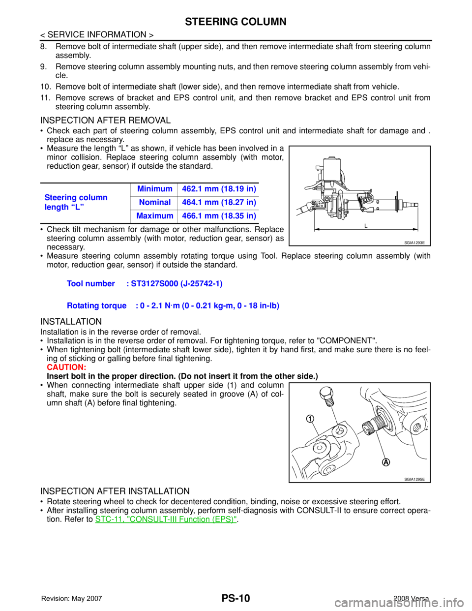
• Measure the length “L” as shown, if vehicle has been involved in a
minor collision. Replace steering column assembly (with motor,
reduction gear, sensor) if outside the standard.
• Check tilt mechanism for damage or other malfunctions. Replace
steering column assembly (with motor, reduction gear, sensor) as
necessary.
• Measure steering column assembly rotating torque using Tool. Replace steering column assembly (with
motor, reduction gear, sensor) if outside the standard.
INSTALLATION
Installation is in the reverse order of removal.
• Installation is in the reverse order of removal. For tightening torque, refer to "COMPONENT".
• When tightening bolt (intermediate shaft lower side), tighten it by hand first, and make sure there is no feel-
ing of sticking or galling before final tightening.
CAUTION:
Insert bolt in the proper direction. (Do not insert it from the other side.)
• When connecting intermediate shaft upper side (1) and column
shaft, make sure the bolt is securely seated in groove (A) of col-
umn shaft (A) before final tightening.
INSPECTION AFTER INSTALLATION
• Rotate steering wheel to check for decentered condition, binding, noise or excessive steering effort.
• After installing steering column assembly, perform self-diagnosis with CONSULT-II to ensure correct opera-
tion. Refer to STC-11, "
CONSULT-III Function (EPS)". Steering column
length “L”Minimum 462.1 mm (18.19 in)
Nominal 464.1 mm (18.27 in)
Maximum 466.1 mm (18.35 in)
Tool number : ST3127S000 (J-25742-1)
Rotating torque : 0 - 2.1 N·m (0 - 0.21 kg-m, 0 - 18 in-lb)
SGIA1293E
SGIA1295E
Page 2528 of 2771
RAX-4
< SERVICE INFORMATION >
WHEEL HUB
WHEEL HUB
On-Vehicle Inspection and ServiceINFOID:0000000001703712
• Check the axle and suspension parts for excessive play, wear, or damage.
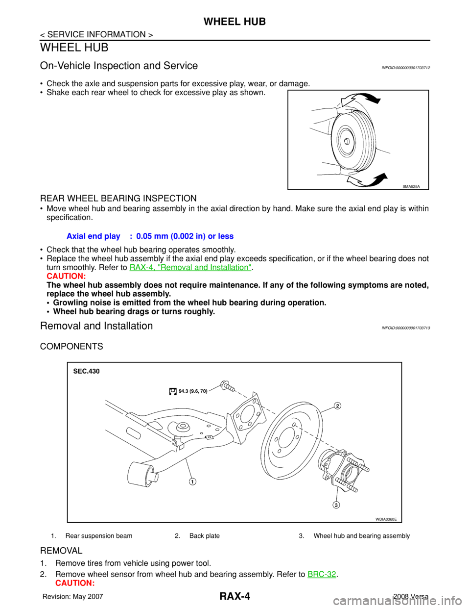
• Shake each rear wheel to check for excessive play as shown.
REAR WHEEL BEARING INSPECTION
• Move wheel hub and bearing assembly in the axial direction by hand. Make sure the axial end play is within
specification.
• Check that the wheel hub bearing operates smoothly.
• Replace the wheel hub assembly if the axial end play exceeds specification, or if the wheel bearing does not
turn smoothly. Refer to RAX-4, "
Removal and Installation".
CAUTION:
The wheel hub assembly does not require maintenance. If any of the following symptoms are noted,
replace the wheel hub assembly.
• Growling noise is emitted from the wheel hub bearing during operation.
• Wheel hub bearing drags or turns roughly.
Removal and InstallationINFOID:0000000001703713
COMPONENTS
REMOVAL
1. Remove tires from vehicle using power tool.
2. Remove wheel sensor from wheel hub and bearing assembly. Refer to BRC-32
.
CAUTION:
SMA525A
Axial end play : 0.05 mm (0.002 in) or less
1. Rear suspension beam 2. Back plate 3. Wheel hub and bearing assembly
WDIA0360E
Page 2529 of 2771
WHEEL HUB
RAX-5
< SERVICE INFORMATION >
C
E
F
G
H
I
J
K
L
MA
B
RAX
N
O
P
Do not pull on wheel sensor harness.
3. Remove the drum brake assembly. Refer to BR-29, "
Removal and Installation of Drum Brake Assembly".
4. Remove wheel hub and bearing assembly bolts, and then remove wheel hub and bearing assembly from
vehicle.
5. If necessary remove back plate, following procedure.
1. Remove parking brake rear cable from back plate. Refer to PB-4
.
2. Separate brake tube from wheel cylinder. Refer to BR-10
.
INSPECTION AFTER REMOVAL
Check for any deformity, cracks, or other damage on the wheel hub assembly, replace if necessary.
CAUTION:
The wheel hub assembly does not require maintenance. If any of the following symptoms are noted,
replace the wheel hub assembly.
• Growling noise is emitted from the wheel hub bearing during operation.
• Wheel hub bearing drags or turns roughly.
INSTALLATION
Installation is in the reverse order of removal.
Page 2564 of 2771
REAR SUSPENSION ASSEMBLY
RSU-5
< SERVICE INFORMATION >
C
D
F
G
H
I
J
K
L
MA
B
RSU
N
O
P
REAR SUSPENSION ASSEMBLY
On-Vehicle Inspection and ServiceINFOID:0000000001703736
Make sure the mounting conditions (looseness, backlash) of each component and component conditions
(wear, damage) are within specifications.
SHOCK ABSORBER INSPECTION
Check shock absorber for oil leakage, damage and replace it if necessary.
Wheel AlignmentInspectionINFOID:0000000001703737
DESCRIPTION
Measure wheel alignment under unladen conditions.
NOTE:
“Unladen conditions” means that fuel, engine coolant, and lubricant are full. Spare tire, jack, hand tools and
mats are in designated positions.
PRELIMINARY
Check the following:
1. Tires for improper air pressure and wear.
2. Road wheels for runout. Refer to WT-5
.
3. Wheel bearing axial end play. Refer to RAX-4, "
On-Vehicle Inspection and Service" .
4. Shock absorber operation.
5. Each mounting part of suspension for looseness and deformation.
6. Rear suspension beam for cracks, deformation, and other damage.
7. Vehicle height (posture).
GENERAL INFORMATION AND RECOMMENDATIONS
1. A Four-Wheel Thrust Alignment should be performed.
• This type of alignment is recommended for any NISSAN vehicle.
• The four-wheel “thrust” process helps ensure that the vehicle is properly aligned and the steering wheel
is centered.
• The alignment machine itself should be capable of accepting any NISSAN vehicle.
• The alignment machine should be checked to ensure that it is level.
2. Make sure the alignment machine is properly calibrated.
• Your alignment machine should be regularly calibrated in order to give correct information.
• Check with the manufacturer of your specific alignment machine for their recommended Service/Cali-
bration Schedule.
THE ALIGNMENT PROCESS
IMPORTANT: Use only the alignment specifications listed in this Service Manual. Refer to RSU-12, "Wheel
Alignment (Unladen*)" .
1. When displaying the alignment settings, many alignment machines use “indicators”: (Green/red, plus or
minus, Go/No Go). Do NOT use these indicators.
• The alignment specifications programmed into your alignment machine that operate these indicators
may not be correct.
• This may result in an ERROR.
2. Some newer alignment machines are equipped with an optional “Rolling Compensation” method to “com-
pensate” the sensors (alignment targets or head units). Do NOT use this “Rolling Compensation”
method.
• Use the “Jacking Compensation” method. After installing the alignment targets or head units, raise the
vehicle and rotate the wheels 1/2 turn both ways.
• See Instructions in the alignment machine you are using for more information.
CAMBER INSPECTION