Page 1988 of 2771

IP-22
< ON-VEHICLE REPAIR >
INSTRUMENT PANEL ASSEMBLY
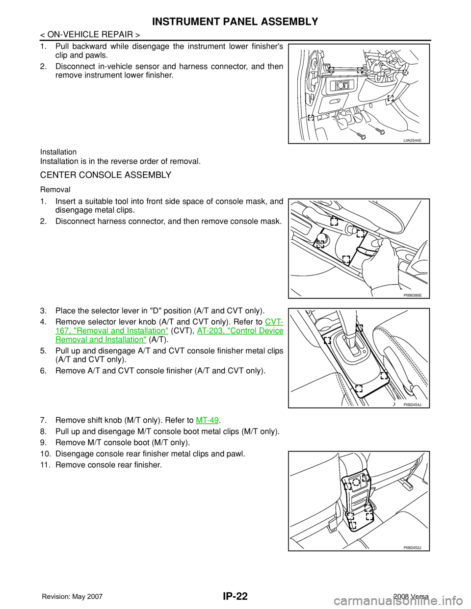
1. Pull backward while disengage the instrument lower finisher's
clip and pawls.
2. Disconnect in-vehicle sensor and harness connector, and then
remove instrument lower finisher.
Installation
Installation is in the reverse order of removal.
CENTER CONSOLE ASSEMBLY
Removal
1. Insert a suitable tool into front side space of console mask, and
disengage metal clips.
2. Disconnect harness connector, and then remove console mask.
3. Place the selector lever in "D" position (A/T and CVT only).
4. Remove selector lever knob (A/T and CVT only). Refer to CVT-
167, "Removal and Installation" (CVT), AT-203, "Control Device
Removal and Installation" (A/T).
5. Pull up and disengage A/T and CVT console finisher metal clips
(A/T and CVT only).
6. Remove A/T and CVT console finisher (A/T and CVT only).
7. Remove shift knob (M/T only). Refer to MT-49
.
8. Pull up and disengage M/T console boot metal clips (M/T only).
9. Remove M/T console boot (M/T only).
10. Disengage console rear finisher metal clips and pawl.
11. Remove console rear finisher.
LIIA2544E
PIIB6386E
PIIB2454J
PIIB2452J
Page 2011 of 2771
LAN-20
< HOW TO USE THIS MANUAL >[CAN]
HOW TO USE THIS SECTION
HOW TO USE THIS MANUAL
HOW TO USE THIS SECTION
CautionINFOID:0000000001711213
• This section describes information peculiar to a vehicle and inspection procedures.
• For trouble diagnosis procedure, refer to LAN-15, "
Trouble Diagnosis Procedure".
Abbreviation ListINFOID:0000000001711214
Unit name abbreviations in CONSULT-III CAN diagnosis and in this section are as per the following list.
Abbreviation Unit name
A-BAG Air bag diagnosis sensor unit
ABS ABS actuator and electric unit (control unit)
BCM BCM
DLC Data link connector
ECM ECM
EPS EPS control unit
I-KEY Intelligent Key unit
IPDM-E IPDM E/R
M&A Combination meter
TCM TCM
Page 2015 of 2771
![NISSAN LATIO 2008 Service Repair Manual LAN-24
< FUNCTION DIAGNOSIS >[CAN]
CAN COMMUNICATION SYSTEM
Engine coolant temperature signal T R
Engine speed signal T R R
Engine status signal T R
Fuel consumption monitor signal T R
Malfunction ind NISSAN LATIO 2008 Service Repair Manual LAN-24
< FUNCTION DIAGNOSIS >[CAN]
CAN COMMUNICATION SYSTEM
Engine coolant temperature signal T R
Engine speed signal T R R
Engine status signal T R
Fuel consumption monitor signal T R
Malfunction ind](/manual-img/5/57360/w960_57360-2014.png)
LAN-24
< FUNCTION DIAGNOSIS >[CAN]
CAN COMMUNICATION SYSTEM
Engine coolant temperature signal T R
Engine speed signal T R R
Engine status signal T R
Fuel consumption monitor signal T R
Malfunction indicator lamp signal T R
Wide open throttle position signal T R R
A/C switch signal R T
Blower fan motor switch signal R T
Buzzer output signalTR
TR
Day time running light request signal
*3TR R
Door lock/unlock status signal T R
Door switch signal T R R R
Front wiper request signal T R
High beam request signal T R R
Horn chirp signal T R
Ignition switch signal T R
Low beam request signal T R
Position lights request signal T R R
Rear window defogger switch signal T R
Sleep/wake up signalRT
TRR R
Theft warning horn request signal T R
Tire pressure signal
*4TR
Trunk open/close status signal T R
Turn indicator signal T R
EPS operation signal R T
EPS warning lamp signal T R
Door lock/unlock/trunk open request signal R T
Hazard request signal R T
Ignition knob switch signal R T
KEY warning lamp signal T R
LOCK warning lamp signal T R
Panic alarm request signal R T
Fuel level sensor signal R T
Overdrive control switch signal T R R
P/N range signal T R
Stop lamp switch signal T R R
Vehicle speed signalRRR T
RRRT R
R
*5R*5T*5
ABS warning lamp signal R TSignal name/Connecting unit
ECM
BCM
EPS
I-KEY
M&A
ABS
TCM
*1
TCM
*2
IPDM-E
Page 2016 of 2771
CAN COMMUNICATION SYSTEM
LAN-25
< FUNCTION DIAGNOSIS >[CAN]
C
D
E
F
G
H
I
J
L
MA
B
LAN
N
O
P
*1: A/T models
*2: CVT models
*3: Models for Canada
*4: Models for USA
*5: Models without ABS
NOTE:
CAN data of the air bag diagnosis sensor unit is not used by usual service work, thus it is omitted.
Brake warning lamp signal R T
A/T check indicator signal R T
A/T self-diagnosis signal R T
OD OFF indicator signal R T
Output shaft revolution signal R T T
Shift position indicator signal R T T
Turbine revolution signal R T
CVT self-diagnosis signal R T
Input shaft revolution signal R T
OD OFF indicator signal R T
Front wiper stop position signal R T
High beam status signal RT
Low beam status signal RT
Oil pressure switch signal R T
Rear window defogger control signal RT Signal name/Connecting unit
ECM
BCM
EPS
I-KEY
M&A
ABS
TCM
*1
TCM
*2
IPDM-E
Page 2017 of 2771
LAN-26
< COMPONENT DIAGNOSIS >[CAN]
CAN COMMUNICATION SYSTEM
COMPONENT DIAGNOSIS
CAN COMMUNICATION SYSTEM
Component Parts LocationINFOID:0000000001711221
1. BCM M18 2. ABS actuator and electric unit (con-
trol unit) E333. IPDM E/R E46
4. ECM E16 5. EPS control unit M53 6. TCM E31
7. Combination meter M24 8. Data link connector M22 9. Air bag diagnosis sensor unit M35
10. Intelligent Key unit M52
BKIA0270E
Page 2236 of 2771

INTERIOR ROOM LAMP
LT-99
< SERVICE INFORMATION >
C
D
E
F
G
H
I
J
L
MA
B
LT
N
O
P
3. Perform the preliminary check. Refer to LT-99, "Preliminary Check" .
4. Check symptom and repair or replace the cause of the malfunction.
5. Does the interior room lamp operate normally? If YES, GO TO 6. If NO, GO TO 4.
6. Inspection End
Preliminary CheckINFOID:0000000001704474
CHECK POWER SUPPLY AND GROUND CIRCUIT FOR BCM
Refer to BCS-15, "BCM Power Supply and Ground Circuit Inspection" .
CHECK POWER SUPPLY AND GROUND CIRCUIT FOR IPDM E/R
Refer to LT- 11 , "Preliminary Check" .
CONSULT-III Function (BCM)INFOID:0000000001704475
Refer to LT- 11 , "CONSULT-III Function (BCM)".
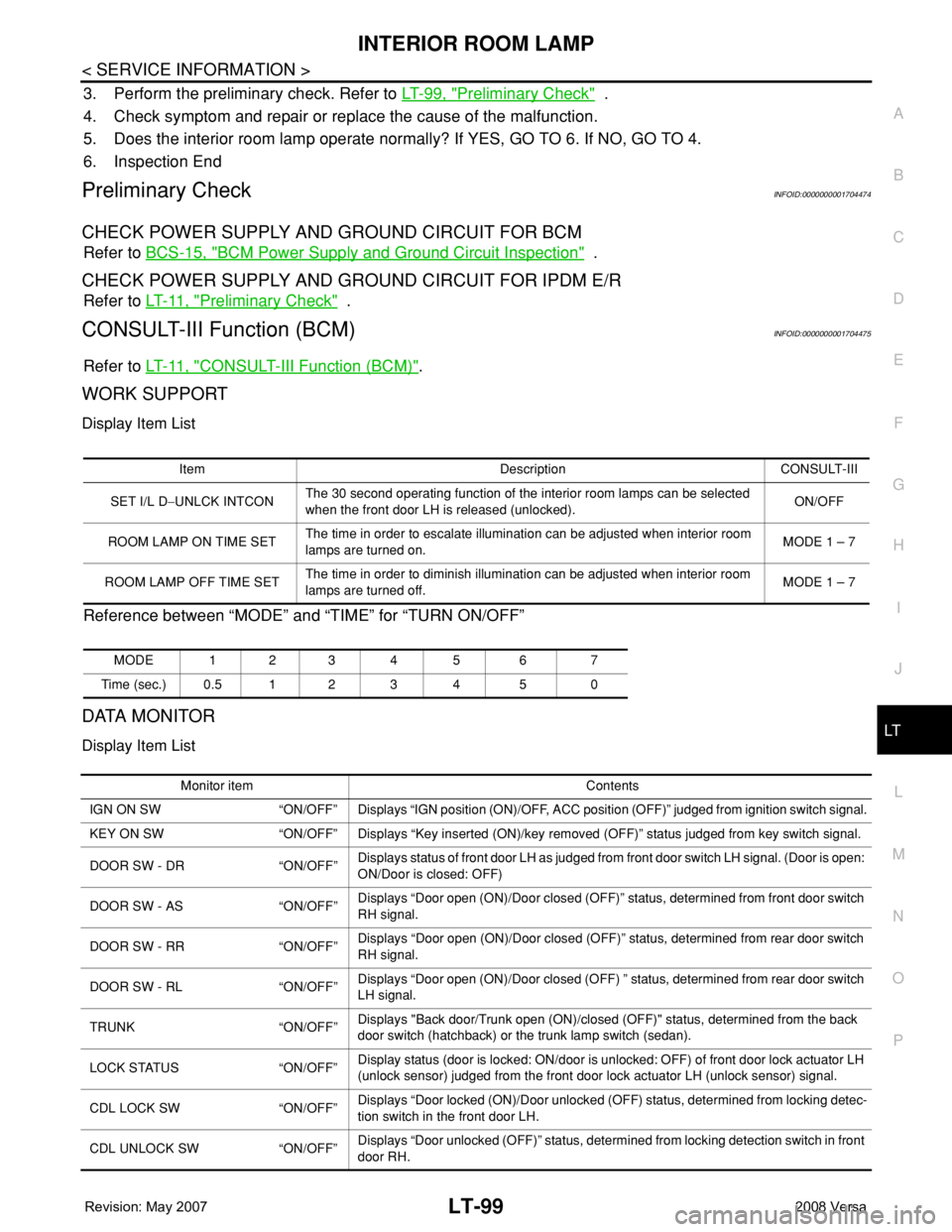
WORK SUPPORT
Display Item List
Reference between “MODE” and “TIME” for “TURN ON/OFF”
DATA MONITOR
Display Item List
Item Description CONSULT-III
SET I/L D−UNLCK INTCONThe 30 second operating function of the interior room lamps can be selected
when the front door LH is released (unlocked). ON/OFF
ROOM LAMP ON TIME SETThe time in order to escalate illumination can be adjusted when interior room
lamps are turned on.MODE 1 – 7
ROOM LAMP OFF TIME SETThe time in order to diminish illumination can be adjusted when interior room
lamps are turned off.MODE 1 – 7
MODE 123 4 5 6 7
Time (sec.) 0.5 1 2 3 4 5 0
Monitor item Contents
IGN ON SW “ON/OFF” Displays “IGN position (ON)/OFF, ACC position (OFF)” judged from ignition switch signal.
KEY ON SW “ON/OFF” Displays “Key inserted (ON)/key removed (OFF)” status judged from key switch signal.
DOOR SW - DR “ON/OFF”Displays status of front door LH as judged from front door switch LH signal. (Door is open:
ON/Door is closed: OFF)
DOOR SW - AS “ON/OFF”Displays “Door open (ON)/Door closed (OFF)” status, determined from front door switch
RH signal.
DOOR SW - RR “ON/OFF”Displays “Door open (ON)/Door closed (OFF)” status, determined from rear door switch
RH signal.
DOOR SW - RL “ON/OFF”Displays “Door open (ON)/Door closed (OFF) ” status, determined from rear door switch
LH signal.
TRUNK “ON/OFF”Displays "Back door/Trunk open (ON)/closed (OFF)" status, determined from the back
door switch (hatchback) or the trunk lamp switch (sedan).
LOCK STATUS “ON/OFF”Display status (door is locked: ON/door is unlocked: OFF) of front door lock actuator LH
(unlock sensor) judged from the front door lock actuator LH (unlock sensor) signal.
CDL LOCK SW “ON/OFF”Displays “Door locked (ON)/Door unlocked (OFF) status, determined from locking detec-
tion switch in the front door LH.
CDL UNLOCK SW “ON/OFF”Displays “Door unlocked (OFF)” status, determined from locking detection switch in front
door RH.
Page 2254 of 2771
LU-4
< SERVICE INFORMATION >
PREPARATION
Tool nameDescription
Power toolLoosening nuts and bolts
Deep socketRemoving and installing oil pressure sensor
a: 26 mm (1.02 in)
PBIC0190E
PBIC2072E
Page 2340 of 2771

MTC-2
DUCTS AND GRILLES ......................................69
Removal and Installation ........................................69
REFRIGERANT LINES ......................................74
HFC-134a (R-134a) Service Procedure .................74
Component .............................................................76
Removal and Installation of Compressor ................78
Removal and Installation of Low-Pressure Flexi-
ble Hose .................................................................
79
Removal and Installation of High-pressure Flexi-
ble Hose .................................................................
80
Removal and Installation of High-pressure Pipe ....81
Removal and Installation of Refrigerant Pressure
Sensor ....................................................................
81
Removal and Installation of Condenser ..................82
Removal and Installation of Liquid Tank .................82
Removal and Installation of Evaporator ..................83
Removal and Installation of Expansion Valve .........84
Checking of Refrigerant Leaks ................................84
Checking System for Leaks Using the Fluorescent
Leak Detector ..........................................................
85
Dye Injection ...........................................................85
Electronic Refrigerant Leak Detector ......................85
SERVICE DATA AND SPECIFICATIONS
(SDS) .................................................................
88
Compressor ............................................................88
Oil ............................................................................88
Refrigerant ..............................................................88
Engine Idling Speed ................................................88
Belt Tension ............................................................88