Page 2546 of 2771
RF-16
< FUNCTION DIAGNOSIS >
TROUBLE DIAGNOSIS
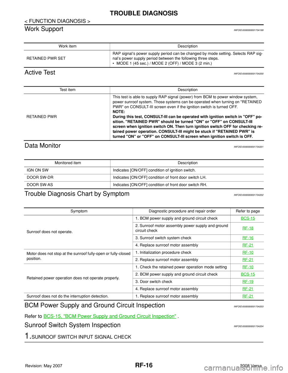
Work Support
INFOID:0000000001704199
Active TestINFOID:0000000001704200
Data MonitorINFOID:0000000001704201
Trouble Diagnosis Chart by SymptomINFOID:0000000001704202
BCM Power Supply and Ground Circuit InspectionINFOID:0000000001704203
Refer to BCS-15, "BCM Power Supply and Ground Circuit Inspection" .
Sunroof Switch System InspectionINFOID:0000000001704204
1.SUNROOF SWITCH INPUT SIGNAL CHECK
Work item Description
RETAINED PWR SETRAP signal’s power supply period can be changed by mode setting. Selects RAP sig-
nal’s power supply period between the following three steps.
• MODE 1 (45 sec.) / MODE 2 (OFF) / MODE 3 (2 min.)
Test item Description
RETAINED PWRThis test is able to supply RAP signal (power) from BCM to power window system,
power sunroof system. Those systems can be operated when turning on "RETAINED
PWR" on CONSULT-III screen even if the ignition switch is turned OFF.
NOTE:
During this test, CONSULT-III can be operated with ignition switch in "OFF" po-
sition. "RETAINED PWR" should be turned "ON" or "OFF" on CONSULT-III
screen when ignition switch ON. Then turn ignition switch OFF for checking re-
tained power operation. CONSULT-III might be stuck if "RETAINED PWR" is
turned "ON" or "OFF" on CONSULT-III screen when ignition switch is OFF.
Monitored item Description
IGN ON SW Indicates [ON/OFF] condition of ignition switch.
DOOR SW-DR Indicates [ON/OFF] condition of front door switch LH.
DOOR SW-AS Indicates [ON/OFF] condition of front door switch RH.
Symptom Diagnostic procedure and repair order Refer to page
Sunroof does not operate.1. BCM power supply and ground circuit checkBCS-15
2. Sunroof motor assembly power supply and ground
circuit checkRF-18
3. Sunroof switch system checkRF-16
4. Replace sunroof motor assemblyRF-21
Motor does not stop at the sunroof fully-open or fully-closed
position.1. Initialization procedure checkRF-10
2. Replace sunroof motor assemblyRF-21
Retained power operation does not operate properly.1. Check the retained power operation mode settingRF-102. BCM power supply and ground circuit checkBCS-15
3. Door switch checkRF-19
4. Replace sunroof motor assemblyRF-21
Sunroof does not do the interruption detection. 1. Replace sunroof motor assemblyRF-21
Page 2547 of 2771
TROUBLE DIAGNOSIS
RF-17
< FUNCTION DIAGNOSIS >
C
D
E
F
G
H
J
K
L
MA
B
RF
N
O
P
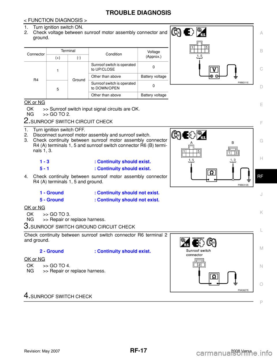
1. Turn ignition switch ON.
2. Check voltage between sunroof motor assembly connector and
ground.
OK or NG
OK >> Sunroof switch input signal circuits are OK.
NG >> GO TO 2.
2.SUNROOF SWITCH CIRCUIT CHECK
1. Turn ignition switch OFF.
2. Disconnect sunroof motor assembly and sunroof switch.
3. Check continuity between sunroof motor assembly connector
R4 (A) terminals 1, 5 and sunroof switch connector R6 (B) termi-
nals 1, 3.
4. Check continuity between sunroof motor assembly connector
R4 (A) terminals 1, 5 and ground.
OK or NG
OK >> GO TO 3.
NG >> Repair or replace harness.
3.SUNROOF SWITCH GROUND CIRCUIT CHECK
Check continuity between sunroof switch connector R6 terminal 2
and ground.
OK or NG
OK >> GO TO 4.
NG >> Repair or replace harness.
4.SUNROOF SWITCH CHECK
ConnectorTe r m i n a l
ConditionVo l ta g e
(Approx.)
(+) (-)
R41
GroundSunroof switch is operated
to UP/CLOSE0
Other than above Battery voltage
5Sunroof switch is operated
to DOWN/OPEN0
Other than above Battery voltage
PIIB6311E
1 - 3 : Continuity should exist.
5 - 1 : Continuity should exist.
1 - Ground : Continuity should not exist.
5 - Ground : Continuity should not exist.
PIIB6312E
2 - Ground : Continuity should exist.
PIIA3627E
Page 2548 of 2771
RF-18
< FUNCTION DIAGNOSIS >
TROUBLE DIAGNOSIS
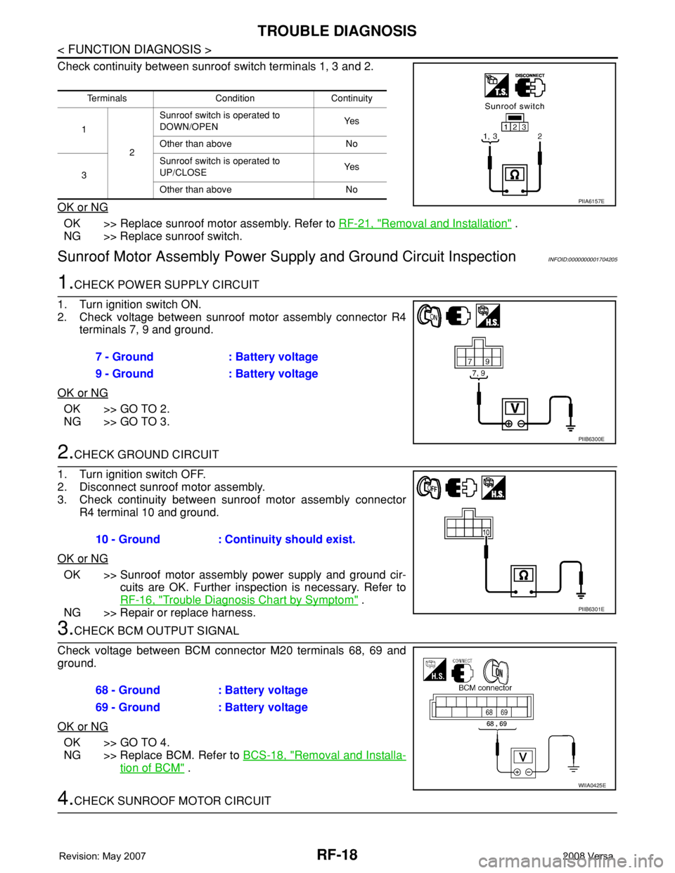
Check continuity between sunroof switch terminals 1, 3 and 2.
OK or NG
OK >> Replace sunroof motor assembly. Refer to RF-21, "Removal and Installation" .
NG >> Replace sunroof switch.
Sunroof Motor Assembly Power Supply and Ground Circuit InspectionINFOID:0000000001704205
1.CHECK POWER SUPPLY CIRCUIT
1. Turn ignition switch ON.
2. Check voltage between sunroof motor assembly connector R4
terminals 7, 9 and ground.
OK or NG
OK >> GO TO 2.
NG >> GO TO 3.
2.CHECK GROUND CIRCUIT
1. Turn ignition switch OFF.
2. Disconnect sunroof motor assembly.
3. Check continuity between sunroof motor assembly connector
R4 terminal 10 and ground.
OK or NG
OK >> Sunroof motor assembly power supply and ground cir-
cuits are OK. Further inspection is necessary. Refer to
RF-16, "
Trouble Diagnosis Chart by Symptom" .
NG >> Repair or replace harness.
3.CHECK BCM OUTPUT SIGNAL
Check voltage between BCM connector M20 terminals 68, 69 and
ground.
OK or NG
OK >> GO TO 4.
NG >> Replace BCM. Refer to BCS-18, "
Removal and Installa-
tion of BCM" .
4.CHECK SUNROOF MOTOR CIRCUIT
Terminals Condition Continuity
1
2Sunroof switch is operated to
DOWN/OPENYe s
Other than above No
3Sunroof switch is operated to
UP/CLOSEYe s
Other than above No
PIIA6157E
7 - Ground : Battery voltage
9 - Ground : Battery voltage
PIIB6300E
10 - Ground : Continuity should exist.
PIIB6301E
68 - Ground : Battery voltage
69 - Ground : Battery voltage
WIIA0425E
Page 2549 of 2771
TROUBLE DIAGNOSIS
RF-19
< FUNCTION DIAGNOSIS >
C
D
E
F
G
H
J
K
L
MA
B
RF
N
O
P
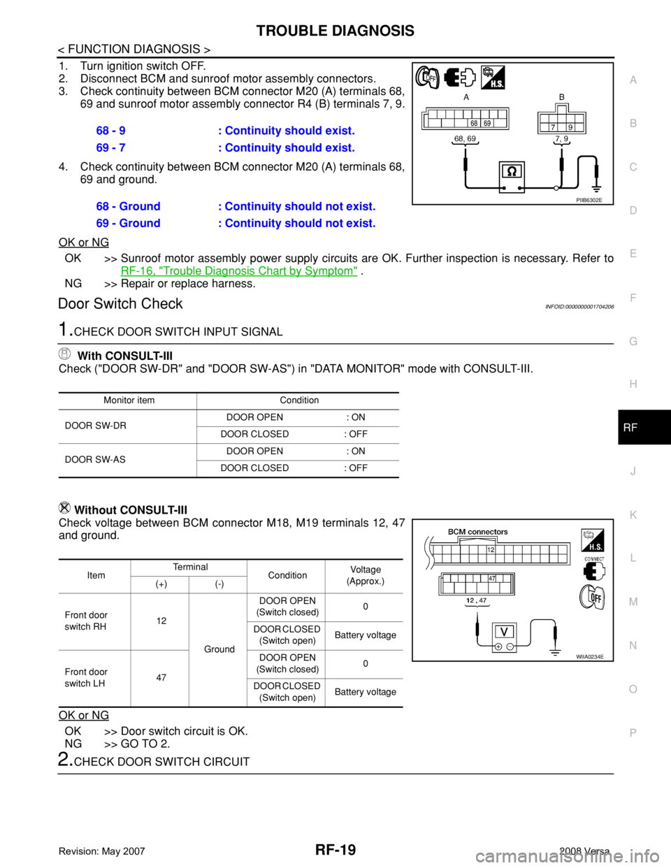
1. Turn ignition switch OFF.
2. Disconnect BCM and sunroof motor assembly connectors.
3. Check continuity between BCM connector M20 (A) terminals 68,
69 and sunroof motor assembly connector R4 (B) terminals 7, 9.
4. Check continuity between BCM connector M20 (A) terminals 68,
69 and ground.
OK or NG
OK >> Sunroof motor assembly power supply circuits are OK. Further inspection is necessary. Refer to
RF-16, "
Trouble Diagnosis Chart by Symptom" .
NG >> Repair or replace harness.
Door Switch CheckINFOID:0000000001704206
1.CHECK DOOR SWITCH INPUT SIGNAL
With CONSULT-III
Check ("DOOR SW-DR" and "DOOR SW-AS") in "DATA MONITOR" mode with CONSULT-III.
Without CONSULT-III
Check voltage between BCM connector M18, M19 terminals 12, 47
and ground.
OK or NG
OK >> Door switch circuit is OK.
NG >> GO TO 2.
2.CHECK DOOR SWITCH CIRCUIT68 - 9 : Continuity should exist.
69 - 7 : Continuity should exist.
68 - Ground : Continuity should not exist.
69 - Ground : Continuity should not exist.
PIIB6302E
Monitor item Condition
DOOR SW-DRDOOR OPEN : ON
DOOR CLOSED : OFF
DOOR SW-ASDOOR OPEN : ON
DOOR CLOSED : OFF
ItemTe r m i n a l
ConditionVoltag e
(Approx.)
(+) (-)
Front door
switch RH12
GroundDOOR OPEN
(Switch closed)0
DOOR CLOSED
(Switch open)Battery voltage
Front door
switch LH47DOOR OPEN
(Switch closed)0
DOOR CLOSED
(Switch open)Battery voltage
WIIA0234E
Page 2551 of 2771
SUNROOF
RF-21
< ON-VEHICLE REPAIR >
C
D
E
F
G
H
J
K
L
MA
B
RF
N
O
P
ON-VEHICLE REPAIR
SUNROOF
Removal and InstallationINFOID:0000000001704207
CAUTION:
• After installation or any adjustment, check clearances for sunroof operation and glass lid alignment.
• Handle glass lid with care to prevent damage.
• Fully close the glass lid before removal, then do not operate sunroof motor assembly after removal.
• When removing sunroof unit assembly, use shop cloths to protect the seats and trim from damage.
• Always work with a helper.
NOTE:
For easy installation, mark each point before removal.
Page 2552 of 2771
RF-22
< ON-VEHICLE REPAIR >
SUNROOF
SUNROOF UNIT ASSEMBLY
1. Glass lid 2. Rear drain assembly 3. Link assembly (RH)
4. Sunroof bracket 5. Wind deflector 6. Drain hose
7. Sunroof unit assembly 8. Sunroof motor assembly 9. Sunshade
10. Sunshade stopper 11. Link assembly (LH)⇐Vehicle front
WIIA1243E
Page 2553 of 2771
SUNROOF
RF-23
< ON-VEHICLE REPAIR >
C
D
E
F
G
H
J
K
L
MA
B
RF
N
O
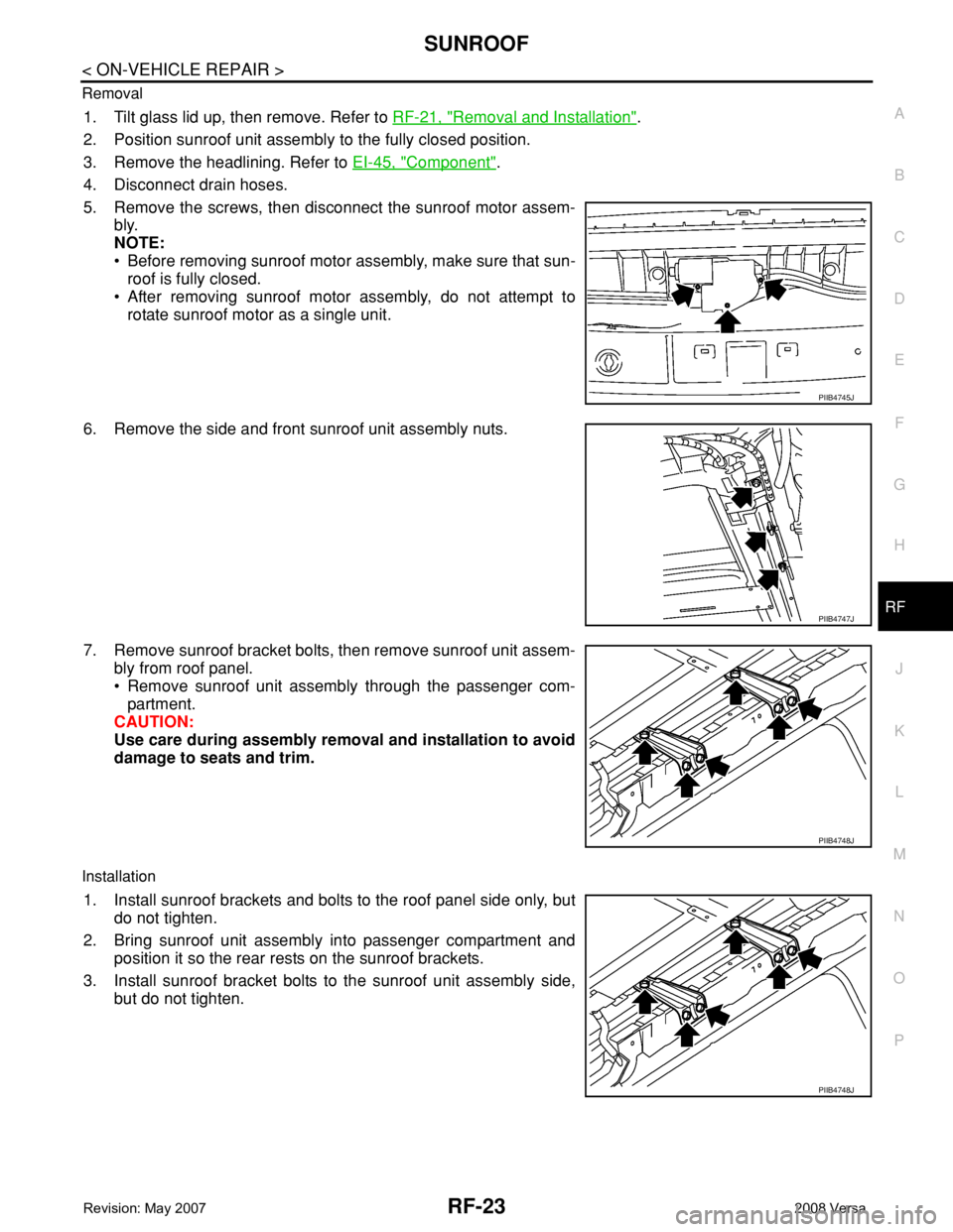
P Removal
1. Tilt glass lid up, then remove. Refer to RF-21, "Removal and Installation".
2. Position sunroof unit assembly to the fully closed position.
3. Remove the headlining. Refer to EI-45, "
Component".
4. Disconnect drain hoses.
5. Remove the screws, then disconnect the sunroof motor assem-
bly.
NOTE:
• Before removing sunroof motor assembly, make sure that sun-
roof is fully closed.
• After removing sunroof motor assembly, do not attempt to
rotate sunroof motor as a single unit.
6. Remove the side and front sunroof unit assembly nuts.
7. Remove sunroof bracket bolts, then remove sunroof unit assem-
bly from roof panel.
• Remove sunroof unit assembly through the passenger com-
partment.
CAUTION:
Use care during assembly removal and installation to avoid
damage to seats and trim.
Installation
1. Install sunroof brackets and bolts to the roof panel side only, but
do not tighten.
2. Bring sunroof unit assembly into passenger compartment and
position it so the rear rests on the sunroof brackets.
3. Install sunroof bracket bolts to the sunroof unit assembly side,
but do not tighten.
PIIB4745J
PIIB4747J
PIIB4748J
PIIB4748J
Page 2554 of 2771
RF-24
< ON-VEHICLE REPAIR >
SUNROOF
4. Install the front and side sunroof unit assembly nuts, but do not
tighten.
5. Tighten the sunroof unit assembly.
a. First, tighten the sunroof bracket bolts at the vehicle side, then
tighten the bolt on the rail side.
b. Next, tighten the front and side sunroof unit assembly nuts diag-
onally.
6.7. Connect the sunroof motor assembly connector and install the
screws.
8. Install the glass lid. Refer to "GLASS LID" .
9. Connect drain hoses.
10. Install headlining. Refer to EI-45, "
Component".
11. Perform fitting adjustment and test for leaks, refer to RF-26, "
Fitting Adjustment" .
GLASS LID
Removal
1. Open the sunshade fully and close the glass lid.
2. Remove glass lid bolts, then remove glass lid.
Installation
PIIB4746J
PIIB4748J
PIIB4745J
PIIB4749J