Page 1669 of 2771
EI-46
< ON-VEHICLE REPAIR >
HEADLINING
Sedan Models
7. Roof console/map lamp assembly (if
equipped)8. Antenna feeder cable 9. Room lamp
10. Dual lock fastener 11. Room lamp harness 12. Insulator
13. Finisher A. With sunroof B. Without sunroof
Metal clip Clip C103⇐Vehicle front
LIIA2925E
Page 1670 of 2771
HEADLINING
EI-47
< ON-VEHICLE REPAIR >
C
D
E
F
G
H
J
K
L
MA
B
EI
N
O
P
Removal and Installation - HatchbackINFOID:0000000001704240
REMOVAL
1. Remove the negative and positive battery cables.
2. Remove front seat assembly RH/LH. Refer to SE-11, "
Removal and Installation".
3. Remove rear seat cushion and rear seatback. Refer to SE-15, "
Removal and Installation".
4. Remove front seat belt shoulder anchor RH/LH. Refer to SB-3, "
Removal and Installation of Front Seat
Belt".
5. Remove center console body assembly. Refer to IP-10
.
6. Remove front pillar garnish RH/LH. Refer to EI-38, "
Removal and Installation".
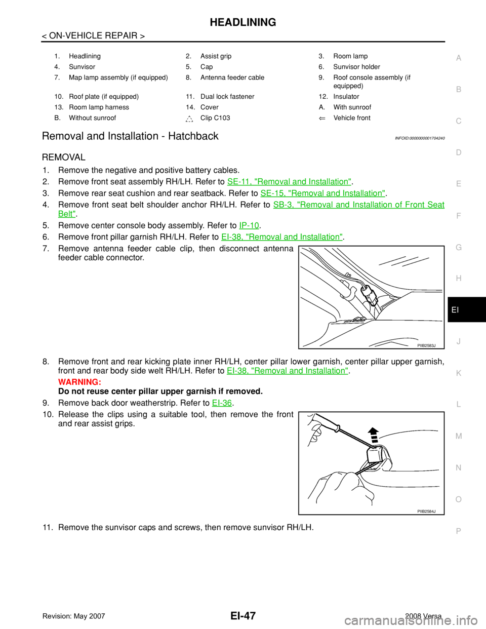
7. Remove antenna feeder cable clip, then disconnect antenna
feeder cable connector.
8. Remove front and rear kicking plate inner RH/LH, center pillar lower garnish, center pillar upper garnish,
front and rear body side welt RH/LH. Refer to EI-38, "
Removal and Installation".
WARNING:
Do not reuse center pillar upper garnish if removed.
9. Remove back door weatherstrip. Refer to EI-36
.
10. Release the clips using a suitable tool, then remove the front
and rear assist grips.
11. Remove the sunvisor caps and screws, then remove sunvisor RH/LH.
1. Headlining 2. Assist grip 3. Room lamp
4. Sunvisor 5. Cap 6. Sunvisor holder
7. Map lamp assembly (if equipped) 8. Antenna feeder cable 9. Roof console assembly (if
equipped)
10. Roof plate (if equipped) 11. Dual lock fastener 12. Insulator
13. Room lamp harness 14. Cover A. With sunroof
B. Without sunroof Clip C103⇐Vehicle front
PIIB2583J
PIIB2584J
Page 1671 of 2771
EI-48
< ON-VEHICLE REPAIR >
HEADLINING
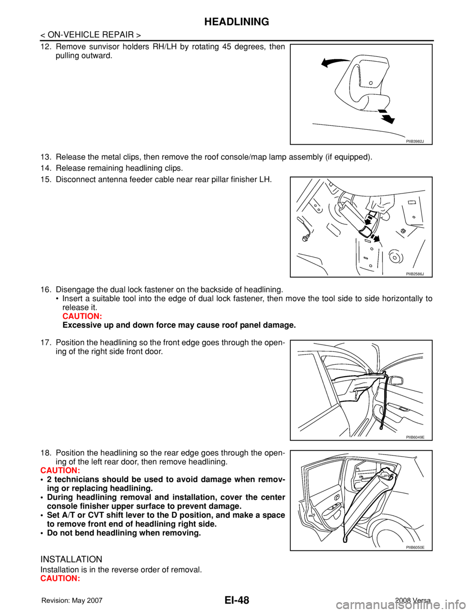
12. Remove sunvisor holders RH/LH by rotating 45 degrees, then
pulling outward.
13. Release the metal clips, then remove the roof console/map lamp assembly (if equipped).
14. Release remaining headlining clips.
15. Disconnect antenna feeder cable near rear pillar finisher LH.
16. Disengage the dual lock fastener on the backside of headlining.
• Insert a suitable tool into the edge of dual lock fastener, then move the tool side to side horizontally to
release it.
CAUTION:
Excessive up and down force may cause roof panel damage.
17. Position the headlining so the front edge goes through the open-
ing of the right side front door.
18. Position the headlining so the rear edge goes through the open-
ing of the left rear door, then remove headlining.
CAUTION:
• 2 technicians should be used to avoid damage when remov-
ing or replacing headlining.
• During headlining removal and installation, cover the center
console finisher upper surface to prevent damage.
• Set A/T or CVT shift lever to the D position, and make a space
to remove front end of headlining right side.
• Do not bend headlining when removing.
INSTALLATION
Installation is in the reverse order of removal.
CAUTION:
PIIB3982J
PIIB2586J
PIIB6049E
PIIB6050E
Page 1672 of 2771
HEADLINING
EI-49
< ON-VEHICLE REPAIR >
C
D
E
F
G
H
J
K
L
MA
B
EI
N
O
P
Avoid headlining damage when installing by inserting rear clips first during assembly.
Removal and Installation - SedanINFOID:0000000001704241
REMOVAL
1. Remove the negative and positive battery cables.
2. Remove front seat assembly RH/LH. Refer to SE-11, "
Removal and Installation".
3. Remove rear seat cushion and rear seatback. Refer to SE-15, "
Removal and Installation".
4. Remove front seat belt shoulder anchor RH/LH. Refer to SB-3, "
Removal and Installation of Front Seat
Belt".
5. Remove center console body assembly. Refer to IP-10
.
6. Remove front pillar garnish RH/LH. Refer to EI-38, "
Removal and Installation".
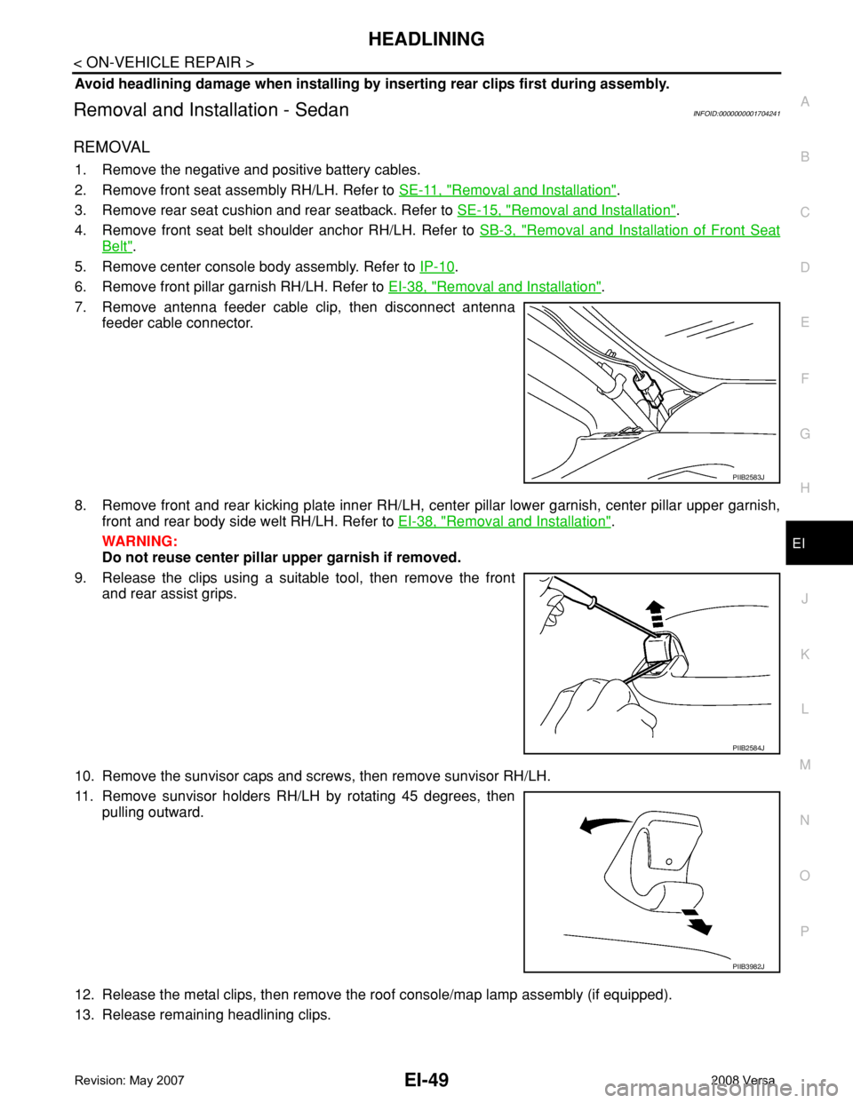
7. Remove antenna feeder cable clip, then disconnect antenna
feeder cable connector.
8. Remove front and rear kicking plate inner RH/LH, center pillar lower garnish, center pillar upper garnish,
front and rear body side welt RH/LH. Refer to EI-38, "
Removal and Installation".
WARNING:
Do not reuse center pillar upper garnish if removed.
9. Release the clips using a suitable tool, then remove the front
and rear assist grips.
10. Remove the sunvisor caps and screws, then remove sunvisor RH/LH.
11. Remove sunvisor holders RH/LH by rotating 45 degrees, then
pulling outward.
12. Release the metal clips, then remove the roof console/map lamp assembly (if equipped).
13. Release remaining headlining clips.
PIIB2583J
PIIB2584J
PIIB3982J
Page 1673 of 2771
EI-50
< ON-VEHICLE REPAIR >
HEADLINING
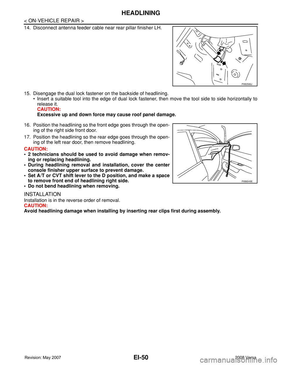
14. Disconnect antenna feeder cable near rear pillar finisher LH.
15. Disengage the dual lock fastener on the backside of headlining.
• Insert a suitable tool into the edge of dual lock fastener, then move the tool side to side horizontally to
release it.
CAUTION:
Excessive up and down force may cause roof panel damage.
16. Position the headlining so the front edge goes through the open-
ing of the right side front door.
17. Position the headlining so the rear edge goes through the open-
ing of the left rear door, then remove headlining.
CAUTION:
• 2 technicians should be used to avoid damage when remov-
ing or replacing headlining.
• During headlining removal and installation, cover the center
console finisher upper surface to prevent damage.
• Set A/T or CVT shift lever to the D position, and make a space
to remove front end of headlining right side.
• Do not bend headlining when removing.
INSTALLATION
Installation is in the reverse order of removal.
CAUTION:
Avoid headlining damage when installing by inserting rear clips first during assembly.
PIIB2586J
PIIB6049E
Page 1824 of 2771
FL-4
< SERVICE INFORMATION >
FUEL SYSTEM
FUEL SYSTEM
Checking Fuel LineINFOID:0000000001703097
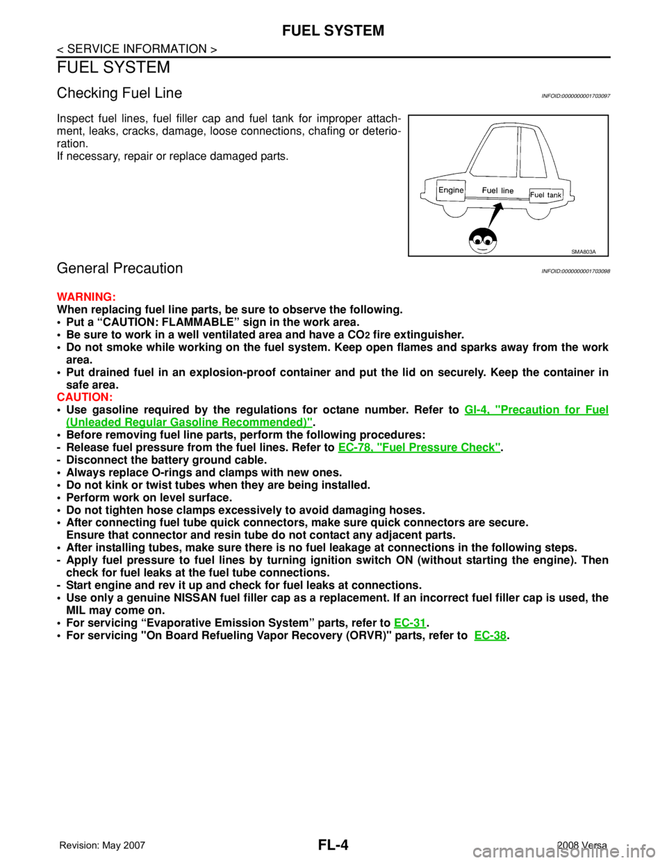
Inspect fuel lines, fuel filler cap and fuel tank for improper attach-
ment, leaks, cracks, damage, loose connections, chafing or deterio-
ration.
If necessary, repair or replace damaged parts.
General PrecautionINFOID:0000000001703098
WARNING:
When replacing fuel line parts, be sure to observe the following.
• Put a “CAUTION: FLAMMABLE” sign in the work area.
• Be sure to work in a well ventilated area and have a CO
2 fire extinguisher.
• Do not smoke while working on the fuel system. Keep open flames and sparks away from the work
area.
• Put drained fuel in an explosion-proof container and put the lid on securely. Keep the container in
safe area.
CAUTION:
• Use gasoline required by the regulations for octane number. Refer to GI-4, "
Precaution for Fuel
(Unleaded Regular Gasoline Recommended)".
• Before removing fuel line parts, perform the following procedures:
- Release fuel pressure from the fuel lines. Refer to EC-78, "
Fuel Pressure Check".
- Disconnect the battery ground cable.
• Always replace O-rings and clamps with new ones.
• Do not kink or twist tubes when they are being installed.
• Perform work on level surface.
• Do not tighten hose clamps excessively to avoid damaging hoses.
• After connecting fuel tube quick connectors, make sure quick connectors are secure.
Ensure that connector and resin tube do not contact any adjacent parts.
• After installing tubes, make sure there is no fuel leakage at connections in the following steps.
- Apply fuel pressure to fuel lines by turning ignition switch ON (without starting the engine). Then
check for fuel leaks at the fuel tube connections.
- Start engine and rev it up and check for fuel leaks at connections.
• Use only a genuine NISSAN fuel filler cap as a replacement. If an incorrect fuel filler cap is used, the
MIL may come on.
• For servicing “Evaporative Emission System” parts, refer to EC-31
.
• For servicing "On Board Refueling Vapor Recovery (ORVR)" parts, refer to EC-38
.
SMA803A
Page 1873 of 2771
GI-22
< SERVICE INFORMATION >
SERVICE INFORMATION FOR ELECTRICAL INCIDENT
SERVICE INFORMATION FOR ELECTRICAL INCIDENT
How to Check TerminalINFOID:0000000001702440
CONNECTOR AND TERMINAL PIN KIT
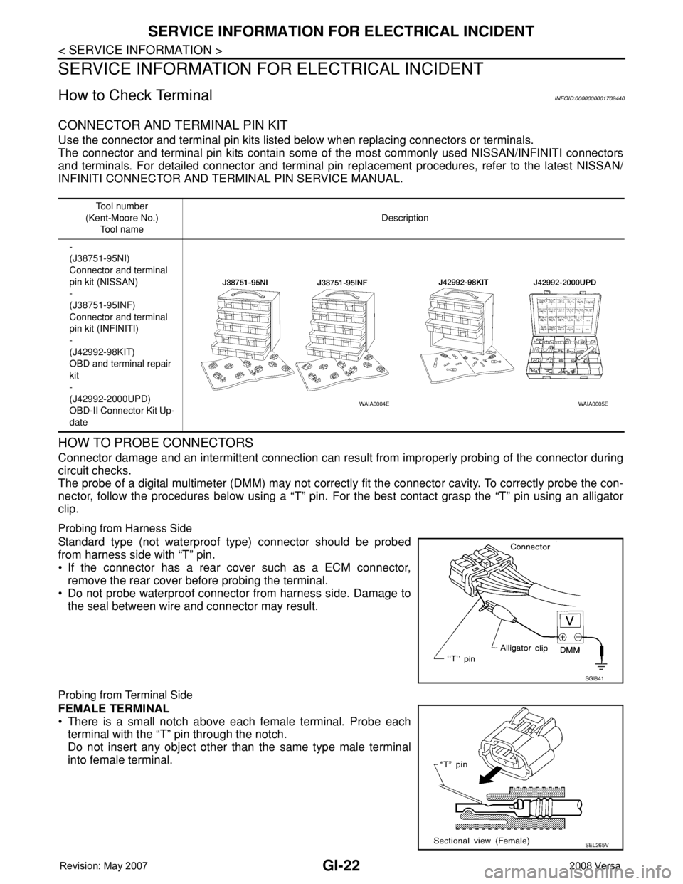
Use the connector and terminal pin kits listed below when replacing connectors or terminals.
The connector and terminal pin kits contain some of the most commonly used NISSAN/INFINITI connectors
and terminals. For detailed connector and terminal pin replacement procedures, refer to the latest NISSAN/
INFINITI CONNECTOR AND TERMINAL PIN SERVICE MANUAL.
HOW TO PROBE CONNECTORS
Connector damage and an intermittent connection can result from improperly probing of the connector during
circuit checks.
The probe of a digital multimeter (DMM) may not correctly fit the connector cavity. To correctly probe the con-
nector, follow the procedures below using a “T” pin. For the best contact grasp the “T” pin using an alligator
clip.
Probing from Harness Side
Standard type (not waterproof type) connector should be probed
from harness side with “T” pin.
• If the connector has a rear cover such as a ECM connector,
remove the rear cover before probing the terminal.
• Do not probe waterproof connector from harness side. Damage to
the seal between wire and connector may result.
Probing from Terminal Side
FEMALE TERMINAL
• There is a small notch above each female terminal. Probe each
terminal with the “T” pin through the notch.
Do not insert any object other than the same type male terminal
into female terminal.
Tool number
(Kent-Moore No.)
Tool nameDescription
-
(J38751-95NI)
Connector and terminal
pin kit (NISSAN)
-
(J38751-95INF)
Connector and terminal
pin kit (INFINITI)
-
(J42992-98KIT)
OBD and terminal repair
kit
-
(J42992-2000UPD)
OBD-II Connector Kit Up-
date
WAIA0004EWAIA0005E
SGI841
SEL265V
Page 1875 of 2771
GI-24
< SERVICE INFORMATION >
SERVICE INFORMATION FOR ELECTRICAL INCIDENT
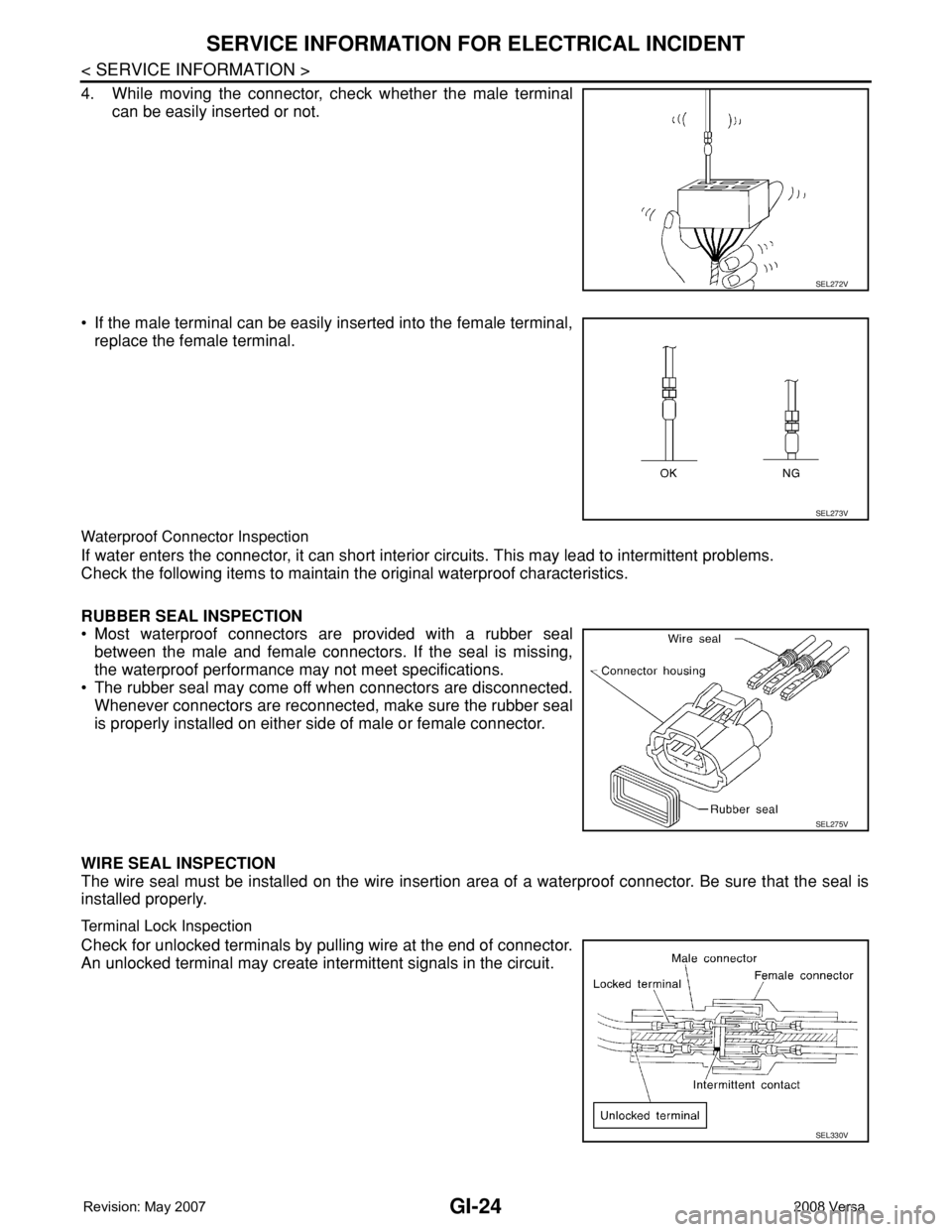
4. While moving the connector, check whether the male terminal
can be easily inserted or not.
• If the male terminal can be easily inserted into the female terminal,
replace the female terminal.
Waterproof Connector Inspection
If water enters the connector, it can short interior circuits. This may lead to intermittent problems.
Check the following items to maintain the original waterproof characteristics.
RUBBER SEAL INSPECTION
• Most waterproof connectors are provided with a rubber seal
between the male and female connectors. If the seal is missing,
the waterproof performance may not meet specifications.
• The rubber seal may come off when connectors are disconnected.
Whenever connectors are reconnected, make sure the rubber seal
is properly installed on either side of male or female connector.
WIRE SEAL INSPECTION
The wire seal must be installed on the wire insertion area of a waterproof connector. Be sure that the seal is
installed properly.
Terminal Lock Inspection
Check for unlocked terminals by pulling wire at the end of connector.
An unlocked terminal may create intermittent signals in the circuit.
SEL272V
SEL273V
SEL275V
SEL330V